Enthalpy
Senior Members
-
Joined
-
Last visited
Everything posted by Enthalpy
-
Hello dear musicians, music lovers and everyone! I'd like to describe fingerings for music instruments with tone holes (which almost means woodwinds) and the associated mechanics. My goals for these fingerings are: Open all holes below the height-defining one, at least on the two first registers; Have no difficult key nor sequence of notes; Not need to close a hole and open an other simultaneously, at least on the two first registers. That's a difficulty of the flute; Need few tone holes regularly spaced and reasonable mechanics; But I don't primarily address the ease or possibility to disassemble the instrument. 1) and 4) make the sound quality more even and let build an instrument with better intonation. To achieve that, my very own personal proposal (... other people have proposed so many!) is: Give one half-tone to the index, middle finger and ring finger of each hand, to cover the upper part of all registers; Continue lower by approximately 4 half-tones with the little fingers. Each has the full set of keys like on the Boehm clarinet; Continue even lower by approximately 5 half-tones with the thumbs. Each has the full set of keys too; Trills near a register limit are made by the little fingers or thumbs, so the registers must overlap. No extra tone hole. Have register keys at the thumbs. Preferably, each thumb has the full set of register keys. The third register and above can't be common to all instruments: an additional register key suffices for some, others need cross fingerings, still others have extra tone holes. One finger for each of the highest six holes make cross fingerings more flexible. Expect differences among the instruments at the two first registers too. The thumbs, being agile in two directions, are the best fingers to operate several keys - bassoon players can confirm. The full set of keys at right and left little fingers is very convenient on the Boehm clarinet, where musicians alternate the notes among the hands. I propose to generalize it to the thumbs, both for lower notes and register keys. Drawings to come should make it clearer. They take me a little time. Marc Schaefer, aka Enthalpy
-
What of the previous ideas could be retrofit on the CL-415 Canadair? The remote control needs "only" control and video transmissions. Since the plane supposedly has hydraulic actuators at all controls, servovalves can be added as alternatives to the manual inputs. This avoids fatalities, since crashes do happen in this job, and lets share the scooper-bomber operator among several aircraft. It also improves the payload. Fuel cells still weigh much: 0.5kg/kW https://en.wikipedia.org/wiki/Toyota_Mirai so replacing 2*1775kW turbines takes 1775kg fuel cells. The electric motors can be lighter, but the hydrogen tanks are heavier. So while the flight duration improves a lot, the payload diminishes. More interesting at a new design, especially if not a flying boat, to my opinion. The in-flight scooping ski makes most sense if not a flying boat, to save structure mass and ease the design. At the CL-415, it would let use shallower waters and save kerosene. It's also safer against debris collisions. Pressure-fed water tanks would avoid to spread the last water inefficiently, and above all, they are a life-saving means against stalling.
-
As an alternative to parylene, the US patent 2,917,499 from 1959 https://www.google.com/patents/US2917499 describes a monomer that can be applied on a surface and polymerizes by air contact. The resulting hydrocarbon polymer layer is water-tight and resists solvents. That would make a thick coating faster than parylene. The patent doesn't describe the possible drawbacks.
-
SpaceX gave information about their future Raptor methane engine https://en.wikipedia.org/wiki/Raptor_(rocket_engine_family) only a true full-flow, including one fuel-rich pre-chamber, can achieve 300bar in the chamber. I've seen no report about soot or not at the pre-chamber and turbine. Soot would make the reuse of the engine more difficult and reduce the efficiency. Thermodynamic equilibrium tells "soot", but maybe the pre-chamber can first have a balanced flame, then quench it at once with the methane, so soot has no time to form at moderate temperature between the pre-chamber and the chamber. In case soot remains an issue, replacing the methane-rich pre-chamber by the recombination of an auxiliary propellant would keep much of Raptor's design and performance. Hydrogen peroxide, hydrazines and methylamine are badly dangerous, but I've described amine mixes that recombine at a good temperature without soot (paperwork!): http://www.scienceforums.net/topic/82965-gas-generator-cycle-for-rocket-engines-variants/ and followings http://www.scienceforums.net/topic/83156-exotic-pumping-cycles-for-rocket-engines/ and followings check for grey shaded tables. Liquid amine mixes can be fed from their tank by helium, and solid ones recompose in their casing, with turbine inlet vanes controlling the pressure hence speed of recomposition. Raptor's vacuum 3.5MN and Isp=382s with 360:100 mix ratio need 203kg/s methane subcooled to 447kg/m3. Liquid injectors to 300bar and a pump, 88% and 74% efficient, take 20.9MW at the shaft. Expanding from 88bar to 1.8bar at a 79% efficient nickel alloy turbine need 23kg/s of added amine mix. This flux, 2.4% of oxygen+methane mass, expands further to 0.4bar and 730m/s to provide roll control and add 17kN (0.5%). The composite Isp drops by 1.9%, but 0.5% more thrust and propellants improve a first stage, whose performance drops by about 1.5%. ---------- An other alternative may be an oxygen-rich staged cycle with a molybdenum alloy turbine to keep a good chamber pressure. At a new engine design, I'd rather have cyclopropane or spiropentane in an oxygen-rich staged cycle, or to smash methane's performance, cool the engine with the oxygen, and burn ethylene or if possible bicyclobutane. Marc Schaefer, aka Enthalpy

-
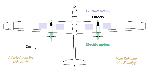
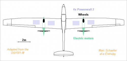
Tesla has improved its batteries and you get a 14kWh Powerwall-2 for 120kg, 1.12m*0.74m*140mm and 5500usd. A battery-powered aircraft looks now less like a demonstrator and more like a vehicle. The following example is adapted from DG Flugzeugbau's DG1001T, thanks http://www.dg-flugzeugbau.de/wp-content/uploads/Flyer-DG-1001T_d.pdf http://www.dg-flugzeugbau.de/en/maintenance-service-aircraft/scale-drawings-gliders Modifications bring the 750kg to: 475kg frame 200kg two people with luggage 480kg four batteries 40kg propulsion and wheels ------------------------------- 1195kg take-off mass The frame mass is kept by giving up the full +7g -5g aerobatic capability. Two main wheels let take-off autonomously; powering them for take-off would be easier than at airliner speed. A longer wing chord keeps the speed. This reduces the lift-to-drag from >46 to estimated 30 at 40m/s = 144km/h = 78knt, so 391N provide the cruise speed. 75% efficiency need 20.9kWe, fitting the Powerwall-2 unit 5kW mean and 7kW peak. The capacity lets fly 2.6h for 370km = 200nm range. Marc Schaefer, aka Enthalpy
-
Hello you all! The present-day tárogató is a not-so-common woodwind with simple reed and conical bore like a saxophone, but with smaller tone holes, fingerings similar to an Oehler clarinet, body made of wood up to now, usually in C, played with clarinet mouthpiece and reed. Estimated 200 copies exist worldwide, mostly in Hungary and Romania. A record of a nicely played one, together with a hammered dulcimer: The tenor tárogató is truly rare - maybe one or two dozens worldwide. The ones I've seen use tenor saxophone reed, mouthpiece and neck, which make them sound more like a sax. Records: (begins at 12 min)and there too
-
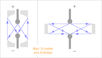
A way to test the breakdown by visible and UV photons is to increase the feedback by adding mirrors. To concentrate light from the anode on the cathode, the left setup bounces it twice on parabolic mirrors, or maybe spherical ones. The right setup bounces light once (smaller losses) on elliptic mirrors, or maybe spherical ones. The right setup eases the insulation at the mirrors, and these can consist of several elements, for instance round ones. Aluminium offers unbeaten 0.8 reflection at 14eV and 0.6 at 15eV. If accepting 0.20, aluminium stops at 16eV, tungsten extends to 24eV and rhenium to 27eV = 46nm. Maybe the index step at Al2O3, TiO2, ZrO2 outperforms metals but it won't be easy. A combination of ceramics, optionally with metal? If the breakdown voltage varies with the area or number of mirrors, one could seek a relation with the solid angle exposed to the anode by the mirrors, and compare it with the cathode's one. Deep UV feedback is compatible with some observations. Smaller electrodes insulate better despite the field concentration, and a little bit of gas improves over vacuum. Marc Schaefer, aka Enthalpy
-
A lens to make the light's electric field more perpendicular to the photocathode was already proposed: https://www.researchgate.net/publication/238665413_FEASIBILITY_TEST_OF_LASER-INDUCED_SCHOTTKY-EFFECT-GATED_PHOTOCATHODE_RF_GUN ========== An experiment report about vacuum insulation, thanks: http://www.dtic.mil/dtic/tr/fulltext/u2/723107.pdf from 1971 but informative. I didn't read all reports, but many try to rescue somehow the disproven emission field model. It seems that Mankind lacks a good theory for vacuum insulation, despite many components rely on it. Measurements from 0µm through 1µm to 30µm distance, round AgNi electrodes: http://psec.uchicago.edu/Papers/Electrical_breakdown_of_small_gaps_in_vacuum.pdf observe 6kV breakdown at 30µm distance, so my unsubstantiated 8kV at 100µm look feasible. They may demand a cathode tip round instead of sharp, more so if the material has a low work function. ========== I suggested on 23 April 2017 that anode fluorescence and cathode photocurrent may cause vacuum breakdown. The linked report for Arpa suggested it already. A way to test this hypothesis for soft X-rays around 100kV is to deposit the same thin layer on varied anode materials like Al, Cu, Mo, Nd, W. The thin layer would give identical work function, optical properties, cleanliness, while the bulk materials vary the X-rays emission. Electrochemical means can deposit 5µm nickel. This lets electrons >40keV pass through, and attenuates X-rays >5keV by <2.7. Semiconductor processes achieve thinner layers of varied materials. For instance 500nm aluminium block visible light, let electrons >6keV pass through, and attenuate X-rays >500eV by <2.7. Thinner is easy. If different anode materials with identical coating give varied breakdown voltages, we can attribute it to X-rays feedback, and varied layer thicknesses indicate which X-ray energy range acts. If a difference is observed, it also suggests how to improve anodes. ========== If it hasn't been done yet, take banal cathode and anode materials but free of radioactivity, and observe the time to failure at ground level and in a tunnel or mine. Marc Schaefer, aka Enthalpy
-
Rather than "Auger", I meant "X-ray fluorescence". A thin layer of molybdenum might be more hermetic than cobalt.
-
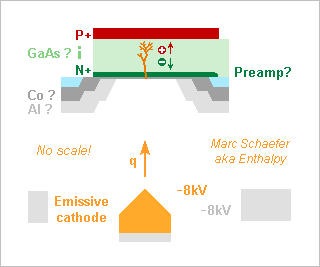
A semiconducting anode would well detect energetic electrons (for instance photoelectrons) whose direct impact creates many carrier pairs. The arrangement is more compact and faster than the many dynodes of a photomultiplier. I had suggested it in 2008 for microscopic vacuum valves, and it is long known for other purposes. Gallium arsenide has a good hole and electron saturation speed, stopping power, resistance to beta rays, and it can integrate the fast preamplifier. Other semiconductors may be better, especially silicon for slower, thicker detectors. 1µm GaAs takes <10ps to collect the charges and stops >8keV photoelectrons that create 1900 pairs. This sketch has no scale. Horizontal and vertical dimensions aren't comparable. 160µm vacuum from the cathode to the anode take 6ps to cross, but I didn't check if the mean 50MV/m let the vacuum break down or provoke field emission. Over 1mm, the transit would increase to 37ps, but because the electrons' energy is uniform to better than +-1eV, the transit time would spread by +-300fs only. Operating near the field emission conditions would extend a photocathode's sensitivity to longer wavelengths. A broad guard ring at the cathode's potential, or even more negative, shall reduce the transverse speed of the emitted electrons. Modelling the field as hemispherical from R=15nm to the R<150nm guard ring, then flat to 160µm distance, the hemispherical part drops ~34V, so 34eV transverse energy let the electrons spread over R=10µm at the anode. A less pessimistic model would bring much. A D=30µm h=1µm GaAs (er=12.9) PIN diode has 80fF capacitance. A HEMT (transistor) on GaAs with 40fF input capacitance and 50ohm noise equivalent resistance creates 110µV = 13aC = 82q RMS noise over 15GHz bandwidth for 20ps bit duration, or +-11 sigma signal from one 8keV electron. Single photoelectron detection at >50Gb/s! The unpolarized diode adds no dark current, the modulation or pulse detection scheme shall make 1/F noise irrelevant, and 10nA gate leakage adds only 1q noise. The diode must be passivated and I don't trust an insulator. Maybe thin cobalt is hermetic enough. Additional metals are often needed for an ohmic contact. The passivation and the first electrode don't waste many pairs, as most appear where the incoming electron stops. If more than one photon created in the passivation or diode (including by radiative recombination) excites the cathode, the mode changes to sustained avalanche. Less convenient for datacomms, sometimes useful for instrumentation. By the way, we still don't have pleasant theories for vacuum breakdown to my knowledge, and this may be one. Integrating the preamplifier at the same chip and face as the diode reduces the parasitic capacitance hence the noise. A preamp at the rear face is nontrivial, stacked chips are possible. If the circuit must be protected from stray 8keV electrons (I didn't check), then >1.1µm aluminium stops the electrons and converts less than 500ppm of the energy flux in photons. 8keV photons would need the chip's thickness to attenuate by 105, but 1.5keV Auger photons are attenuated by e for every 370nm of cobalt thickness. If incoming light isn't perfectly concentrated, a carpet of resonating photocathodes, or a broad smooth photocathode, can target one semiconductor anode. A chip or module can integrate many semiconductor diodes and preamplifiers, for instance to make images or receive many parallel data paths. Marc Schaefer, aka Enthalpy
-
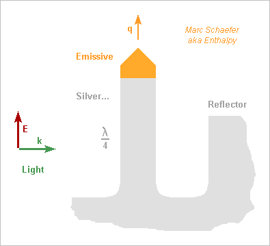
Hello you all! Here, I suggest photocathodes that resonate at the light's frequency like a radiowave antenna to improve the sensitivity. As usual, I didn't check the state of the art, and since antennas for light exist already on solar cells, I could well be late. To increase the field, the cathode has a sharp tip like at some electron guns, and it shall resonate well, but metals are lossy at visible frequencies. Silver must be the best choice, followed by aluminium if the light isn't blue. From the CRC Handbook of Chemistry and Physics, section "optical properties of metals", for silver at 2eV = 620nm = 3*1015rad/s: The extinction coefficient k=4.18 so the current is shallow as compared to the wavelength; The reflectivity is still 0.944 so an incident wave of 1V/m that induces 5.2mA/m dissipates 150µW/m2; I deduce a surface resisitivity of 5.4 ohm/square. The tip needs a different material for emissivity but it conducts nearly no oscillating current. A cylindrical quarter-wave antenna of 30nm diameter with estimated 400nH/m has then j1,2Gohm/m and ohmic losses of 57Mohm/m hence an intrinsic Q~20, which is the desired improvement. If alone over the ground plane, it has also 36ohm radiation resistance which would much reduce the external Q, but we can spoil the radiation resistance and keep a decent inductance. For instance a reflector does that: wide enough, it adds little resistive losses, and if not too high, it lets the electrons escape. This can exaggerate up to a resonating cavity with a small hole letting the emitting tip through and some coupling for the light, like a small hole to adapt a fibre to the cavity. Dielectrics look less useful as they increase the ohmic losses. The antenna can have a wider base to reduce a bit the losses, for instance be conical (and longer to stay tuned). The light's electric field should be roughly parallel to the antenna. Often, flat photocathodes receive light from their normal direction, which I believe is suboptimum; a lens (punched as needed) with big numerical aperture should improve this, or a better orientation. One single antenna can receive light through a lens or from a fibre or guide; semiconductor processes can make the guide in addition to the antenna. Several antennas permit to cover a wider area; when used without a reflector, such an antenna catches electromagnetic power from a fuzzy area of 0.5*Lambda2/4pi, which tells what spacing is meaningful. Closer spacing broadens the frequency band but won't help the sensitivity. ========== A resonating photocathode, if better, has about the same uses as a traditional one. Some specific cases: An electron microscope needs an electron gun as brilliant as possible. Maybe a resonating photocathode improves that. I'd try warm sharp LaB6 at the tip. Multiphoton absorption is worth trying here with enough peak power, that is, even if the work function exceeds the photon energy. Future linear electron colliders have similar needs, but I suppose better answers exist already for them. Datacomms transport light on a tiny cross-section and need sensitive receivers. I already suggested to develop a photomultiplier tube with a small sensitive cathode spot http://www.scienceforums.net/topic/93628-observe-a-falling-charge-radiate/#entry910916 because photomultiplier tubes have already a small dark signal despite their big photocathode at room temperature. To my opinion, this is an easy research project that has good chances to work and is useful for physics instrumentation and for communications, including single-photon cryptography. The resonating photocathode would combine nicely with such a photomultiplier tube. Marc Schaefer, aka Enthalpy
-
A simpler upper bound on the mean deposition rate of calcite: On the pictures, we see less than 175mm calcite added on the construction over 175,000 years. That would be mean <1µm/year between the construction and present time. The rate varied over this time, and is faster at the stalactites. This tiny deposition rate re-opens the remote possibility of terracotta walls. Would have worked better than raw clay, and would explain the traces of fire if necessary - but the oldest known terracotta is 150,000 years younger, from the Sapiens Sapiens.
-
Here's an estimate of the calcite accumulation rate. Speleologists must have better, directly observed figures. Due to vegetation, groundwater can contain much more carbon dioxide than rainwater: 3mmol/L, according to Carbon Dioxide Equilibria and Their Applications, By James N. Butler. This groundwater can dissolve as many 3mmol/L of CaCO3 as bicarbonate and release them as calcite, or 0.3g/L. A reservoir accumulating water drops at 2L/h (100 drops/s from many stalagtites, enough for 20 people) over 20m2 would accumulate calcite (2711kg/m3) at 0.1mm/year if it were uniform - should be more where the drops fall and less at the walls. Walls reinforced with stalagmites and covered with unfired clay need frequent maintenance, so at that rate, calcite wouldn't have accumulated on the walls. But over 20 years, some 2mm calcite may have accumulated at the basin's bottom, with a distribution that hopefully differs from water flowing away. If finding the right calcite layer, this would be an indication for a basin. Layers of calcite depend on each year and their stacking tells a date. I feel easier to check first the composition of the construction stalagmites' surface, which has a different colour. Does this result from fire? Or rather, did some mud, for instance walls' clay, diffuse into the calcite? The bingo would be if the diffused mud has a composition not found nearby in the cave, that is, if the humans have brought clay for their construction.
-
You should check what air throughput a turbofan needs.
-
Hydrogen and fuel cells make good aeroplanes... Other people believe it strongly enough to have developed some. http://www.aviationpros.com/press_release/12264576/hy4-maiden-flight-of-the-hydrogen-powered-airplane This four-seater is still rather slow (150-200km/h) and resembles more a motor glider, but it claims already 750-1500km range, much for this plane category, and a strong advantage of fuel cells. No word about sales, so it must be a demonstrator rather, but to my opinion, its performance is market-ripe. And the members of the team (a wide consortium) speculate loudly about commercial transport soon.
-
Yes. I hesitated at it, and got discouraged by the alleged brittleness. Though, I haven't tested it with my own fingers. I'd prefer the balls to accept significant crushing before the lithium gets exposed, and PP is a candidate for that. I've also had an exorbitant price for PMP in the past, but I suppose it was dishonest. The choice of processing temperature looks rather harmless if lithium is injected in a polyolefin sphere: I suppose it could be done at room temperature, or with very little heating. On the other hand, polyethylene is commonly injected around +200°C which wouldn't fit a lithium sphere, unless thermal inertia does a trick. A lower-melting polyolefin would ease this option of shell-injected-around-lithium. Or if not, back to the liner like Parylene, but thick enough to protect the lithium a bit.
-
Thank you! Li melts at +180°C, Na at +98°C only, polyolefins are injected at a mild temperature that makes them softer.
-
That's why I recommend the non-halogenated Parylene. Do you see other difficulties with that particular coating (or with others I suggested)? Woud lithium prevent the polymerization or induce other reactions? Other alkaline metals have a strong action on alkenes, used for instance for metathesis.
-
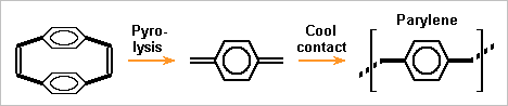
One more primer option is Parylene. Together with halogenated variants, it serves as a conformal coating against moisture on electronic boards. https://en.wikipedia.org/wiki/Parylene Heat splits the precursor to a diene which polymerizes when touching surfaces near room temperature, leaving no voids. Used commonly on metals, ceramics and polymers, but often after a first siloxane layer probably unsuited to lithium. Since adherence isn't vital at the float, I hope to spare the first layer. What lithium does to the monomer is unclear to me; a bit of untypical material is acceptable if the outer material is sound. The price is a drawback: up to 1k$/kg for the precursor and one day to deposit 0.1mm, after what handling and processing is easier. The coating chamber can process many balls. Some kind of moving support like the previous rolls must avoid shadowed locations. ---------- I like increasingly a polyolefin hull on the lithium. Low density permits several mm thickness, and then polyethylene or polypropylene resists shocks, deformations and tearing better than thin metal does. If a polymer is injected around a lithium ball, a shell in two successive parts looks easier. A primer like parylene must ease the operations. Other polyolefins use to need a higher injection temperature, but lithium limits it. ---------- Supposedly, lithium can be injected instead of cast, much like a polymer: heated to a creeping solid rather than a liquid, with much pressure to inject it. Material pressure fills the mould better, preferibly in combination with vacuum. Production is faster as the part is obtained solid. Solidification can make internal voids and a less accurate shape, which injection improves. The shape is more accurate. Lithium injection could be made in the protective hull then. The hull would be nearly complete instead of two halfs, with the injection hole tapped when the lithium is cold. Marc Schaefer, aka Enthalpy
-
Interesting! Up to now, I imagined balls of 1dm3 for instance, or any shape that makes a tighter pack, hold in a net or a holed reservoir. For sure, I want the bathyscaphe to float even if some elements fail, and the failure of one element have consequences of limited size. Whether the elements' size should be 10L, 0.1L or 1mm3, I have no clear opinion. One remote lower limit is the diffusion of water through a too thin barrier. An upper limit is how much alkali and hydrogen are aceptable on the open deck of a large boat, with prepared passive and active safety. If one size makes coating easier, it's a strong argument. Fun: one bathyscaphe had spheres (hollow) of alumina as floats. Brilliant idea, as alumina has a huge resistance to compression compared with its density, and is also extremely stiff, which is all-important because spheres use to fail by buckling under 114MPa. Alas, it wasn't quite clear whether the spheres would really survive the implosion of a neighbour. This bathyscaphe never emerged from one dive, but some little parts did, so people suppose a chain reaction ended the toy's useful life. On this aspect, lithium gives confidence. So much that I feel its drawbacks would be accepted if reasonably under control.
-
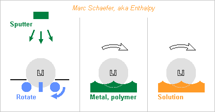
Here are a few paths to cover the lithium with a primer, after which a barrier against water can be deposited, possibly by aqueous chemistry or electrochemistry. Many metals can be sputtered, including corrosion resistent ones, diffusion-tight, hard or malleable, and their alloys. To cover a lithium ball everywhere, I propose to lay it on three or more motorized rolls that turn it around alternating axes - remove previously any linden leaf. Vacuum O-rings on the rolls can improve the adherence if unreactive. Sets of rolls for one rotation axis can carry the ball while others sink to avoid rubbing. The screen can also carry the ball from time to time, and then one roll, or finger(s) or a shaker can rotate the ball. A magazine would process several balls after pumping the chamber once - or have an airlock rather. Metal evaporation looks less easy than sputtering, as the machines I know need the metal source below the target. A material molten below +180°C can solidify upon contact with colder lithium. This enables more varied shapes. Some metals and known alloys melt easily, here eutectic examples: 43Sn-57Bi at +138°C, 48Sn-52In at +117°C, Sn-Bi-In below. Maybe polyolefins and other polymers don't react with lithium and would then make a watertight shell, possibly without any added layer. Injection, in two steps and preferably under vacuum, would be better than deposition. Some electrolytes aren't too corrosive to lithium, for instance the ethylene and propylene glycol carbonates used in lithium batteries. A metal less soluble than lithium might perhaps deposit at the lithium surface, in a displacement reaction similar to iron that covers with copper in copper sulphate. Marc Schaefer, aka Enthalpy
-
The stalagmite parts assembled during the construction look more orange or brown than the others. This is attributed to transformation by fire up to now. But could it be that clay or a similar material, that made the hypothetic reservoir watertight, incorporated to the old or new calcite over time? Analysis would tell that.
-
Referring to the images and drawings, index there http://www.nature.com/nature/journal/vaop/ncurrent/fig_tab/nature18291_ft.html At least now, the construction is at a lower area full of water. This is where I would not settle my camp. http://www.nature.com/nature/journal/vaop/ncurrent/fig_tab/nature18291_SF2.html But the limits of the main construction follow the line of constant altitude rather than a circular or oval shape. Constant altitude makes sense for a reservoir, while a smooth shape is preferred for a tent or a camp. Or possibly, the bottom became flat over a long time when the construction retained water that left sediments. On the magnetic map, the anomalies correspond to the highest artefacts (beware the maps have varied orientations). http://www.nature.com/nature/journal/vaop/ncurrent/fig_tab/nature18291_SF5.html If, as I've seen done in archaeology, the map was acquired by moving the sensor at constant height, the locations of strong anomaly can just result from the artefacts being nearer to the sensor. In both directions of the map, the field gradient increases over 30cm and decreases as quickly, which would fit with a mean sensor altitude of 1m. So maybe the height explains the map, needing no modification in the material. Err, it's very presumptuous to suggest that from an armchair, apologies. One fascinating hypothesis relating fire with a reservoir: mud isn't stable over time in water, so the guys (or the girls) put ceramic instead over the stalagmite structure and fired it in situ. If any necesary, this would explain why the stalagmites are magnetically modified at the highest points: the ceramic was thinner there. The small little difficulty is that the oldest ceramic we know dates 29,000-25,000 BP https://en.wikipedia.org/wiki/Venus_of_Doln%C3%AD_V%C4%9Bstonice corresponding to Sapiens Sapiens era, but, well, you know.
-
Yes: comparing the Sapiens Sapiens' activity 45,000y ago with Neanderthals' 176,500y ago brings little, and the stalagmites as their are arranged obviously didn't serve to support a tent. The orange spots on the nice picture you linked show spots that have been hot. Only the red spot is charred. I suggest that the processing of the stalagmites, especially cutting them, involved heat as a means or a consequence. These stalagmites are 10-20cm diameter stones, so breaking or cutting them needs some doing. A camp fire would not have been made on the stalagmites, and the effect of heat would be observable on the ground too. 20cm spots are also small for a camp fire. By any means, the stalagmites and bones were heated before being assembled.
-
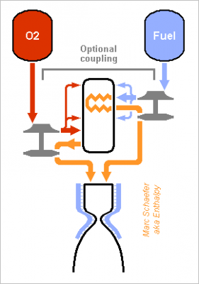
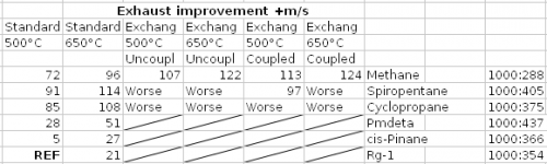
A cycle where the oxygen-rich preburner heats the fuel in an exchanger to turbine it too would look like this: It needs several flame stages in the preburner to regulate all temperatures, possibly several stages at the exchanger. At least, throttling doesn't make the fuel hotter. I've computed the achievable pressures by expanding the gases at constant Cp: the power differs by 2% only from Propep. I've kept RD-170's 535bar at the prechamber, almost as good as 700bar. 500°C at the turbine resulted from oxidation then; I've also checked at 650°C, where nickel alloys creep little enough. I've also compared with RD-170's known oxygen-rich staged combustion. The hypotheses are arbitrary but the comparison is fair. Unzip the two-sheet xls: HybridStagedExchanger.zip ---------- The heat exchanger gains little performance, some 3s Isp, and only for methane supposed to withstand heat. Accepting 10g decomposition products over 300s in 0.16m3 exchanger and ducts at 535bar permits 710°C for methane, 390°C for cyclopropane and 320°C for spiropentane, according to http://kinetics.nist.gov/kinetics/Detail?id=1956SHA/PAV811:1 http://kinetics.nist.gov/kinetics/Detail?id=1961FAL/HUN609-611:1 http://kinetics.nist.gov/kinetics/Detail?id=1972FLO/GIB548:1 and a low temperature can't pay for pumping the fuel to a higher pressure. Coupling the turbopumps brings very little performance. Safer start maybe. But easier seals are more important. Cyclopropane and spiropentane outperform methane as their density lends to a higher pressure, and they shrink the tanks too. The advantage would be bigger at a gas generator cycle or with electric pumps. Cyclopropane is mass-produced, spiropentane could probably be. Methane with a heat exchanger gains only 3s over cyclopropane without. If a fuel-rich pre-burner accepts methane somehow, this comparison will hold. To my opinion, not worth an exchanger nor a second pre-burner. I've included Pmdeta in the table because it's more common than rocket "kerosene", more efficient, more resistent to fire. Safe and more efficient fuels may be possible http://www.chemicalforums.com/index.php?topic=79637.msg290422#msg290422 ---------- The exchanger is as badly difficult as expected. Spark-gap machining and molybdenum, niobium or tantalum alloys may contribute to a solution. Also, a 3s better 450t first stage gains at its end only 2t, which the exchanger can't squander. I won't put time in it. Would methane soot in a fuel-rich pre-burner? The chemical equilibrium tells yes, so kinematics decides. Maybe little methane can burn with enough oxygen, the combustion get enough time to end (still a small throughput), and only then be quenched quickly with abundent methane. Experiments must decide. Marc Schaefer, aka Enthalpy