
Enthalpy
Senior Members
-
Joined
-
Last visited
Everything posted by Enthalpy
-
I described here on Apr 08, 2013 an APU that tells how smaller a motor is if it rotates fast http://www.scienceforums.net/topic/73798-quick-electric-machines/?do=findComment&comment=737931 1270kW machine too, but estimated 16kg for 813Hz instead of 224kg for 20Hz. The two-stage gear needs maintenance and weighs a bit too. An intermediate solution, with a single-stage gear and a medium diameter motor, may be considered too. Planetary (epicyclic) gears are compact and powerful at small electric motors. Would they be good for electric aeroplanes? wikipedia
-
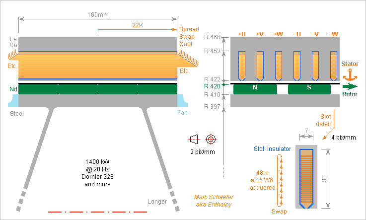
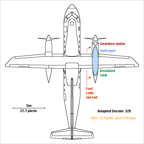
Here's an example of gearless ring motor for the described Dornier 328: 1400kW at 20Hz. 10mm thick Neorec53b magnets (Nd-Fe-B from Tdk) at the D=0.84m rotor move with 52.8m/s and provide 1.16T at +60°C in 2mm gap, of which prestressed graphite composite wound filaments occupy 1mm to hold the magnets. The L=0.16m rotor and 3-phase stator have 24 pole pairs (though differing numbers would cog less). The conductors pass once per pole through an own slot, so the peak voltage is 468V. The magnets are 80% as wide as the poles, so the waveform provides a fundamental amplitude of 1.21*468Vpk. No fractional pitch here, but the slot skew is +-1/7 the pole width, multiplying by 0.967 the fundamental si H1=548Vpk=388Veff and 1400kW take 1203Aeff=1701Apk per phase. The inverter needs inconvenient 1100VDC (if no H3). Multi-turn coils in parallel are more usual and may enable <500VDC, but then only a very symmetric machine avoids stray currents. Fractional pitch would bring known advantages and stay <3000VDC. The bars superimpose 48 flat enamelled e=0.5mm W=6mm conductors that may be lasercut or etched from much bigger sheets for easier turns. I hope to introduce them sequentially in the slots. Estimated with optimism at 0.25m per bar, they show 1.35mohm per phase and lose 5.9kW in total. The 480Hz azimuthal induction in the slots is 0.31Tpk near the teeth, so the eddy currents in the conductors lose 1.4kW in total. I didn't evaluate the radial induction component. The stamped 4mil lamination are of Supermendur (Fe-Co from MKMagnetics) used at 1.87Tpk. This enables three 7mm wide slots per 55mm pole. They lose 40W/kg at 480Hz, or 2.7kW between the slots and 2.2kW outside. All these losses, 12.2kW=0.87%*1400kW, can be conducted away by the bars within 22K if some grease makes the contact with the laminations. Outside the slots, the conductors are spread to cool by ventilation, and they rotate one position in the slot between two slots, as a simpler form or "Litz" (=braided) wire. The stator currents superimpose 94mT at the gap, needing additional 45Vpk in quadrature per phase. The laminations don't saturate. The induction through the slots need additional 71Vpk in quadrature per phase. The machine could be shorter, thicker, lighter. Fractional pitch would ease here. Here are masses in radius order: 54kg Fe-Co external 34kg Cu 68kg Fe-Co between slots 1kg Graphite 25kg Magnets 42kg Steel ------ 224kg Sum The shaft, rings, bearings, casing, fans are not included. More poles would enlighten the motor. Marc Schaefer, aka Enthalpy
-
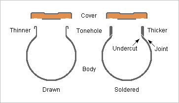
I proposed on Nov 13, 2017 that the wall material can influence the sound by an elliptic vibration around the tone holes http://www.scienceforums.net/topic/111316-woodwind-materials/?do=findComment&comment=1023070 and the effect of the toneholes' nature is consistent with my explanation. As explained by Miyazawa and many more, the toneholes of a flute as of some saxophones can be drawn from the body of soldered on it http://www.miyazawa.com/media-library/educational-articles/options/drawn-vs.-soldered-toneholes/ Drawing the toneholes from the body makes them even thinner, while soldered ones are thicker. The toneholes are the very item that stiffen the instrument against elliptic vibrations there, and the effect of soldered toneholes is said to resemble a thicker body: stronger darker sound. I won't be more positive than "consistent with my explanation", because: I never compared by myself the two hole constructions. So many sales arguments aren't justified! This feature is never an option within a flute series. It characterizes series that have more differences. Soldered tone holes are typically undercut, so the transition from the bore has a bigger and better controlled radius. This knowingly matters. The rim shape may differ. The flow gets easily nonlinear there, and angles would change the sound. I suggested to electroform complete flute joints, the body with the tone holes at once. With denser current or more time, including insulating masks, electroforming can produce locally thicker metal, for instance at and near the tone holes. Marc Schaefer, aka Enthalpy
-
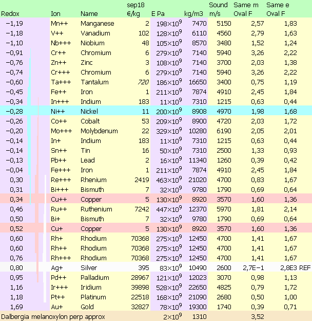
Here's a table of metals ordered by reduction potential, aka standard electrode potential, aka standard reduction potential, from CRC Handbook of Chemistry and Physics, "Electrochemical Series" I've picked metals not very toxic and with a reduction potential not very negative: Mn can be electrowon. Nb, Cr, Zn, Ta are included despite their protective oxide layer because Zn can be electrowon, but alloys may worsen that; brass can be brazed but stainless steel is cumbersome. Only simple ions are listed. V+++ is missing. Polyatomic ions, with less direct reductions, would offer more potentials and enable metalloids. The cost per kg converts Usd, Gbp, Cny, Idr to metric units as of September 2018. I took troy pounds (20% difference). Prices are for multiton amounts of pure metal at stock exchanges except Ta in kg foil by a supplier; the cheaper metals depend more on the amount. The vertical bars extend from Ni, Cu, Ag by +-0.7V because CuNi can be electroformed - no better reason, and electrochemistry is tricky. Even CuZn (span 1.1V) can be electroformed. The oxidation number promises flexibility, but are there interactions? To the commonly electroformed Ni and NiCo, Mo may perhaps keep the corrosion resistance and increase the hardness and stiffness, Zn Cr Ta improve the corrosion resistance but hamper the solderability, Cr increases the stiffness and In Sn Pb Bi decrease it. In electroformed Cu alloys, Mn Zn seem difficult, but there may be tricks like polyatomic ions. Cu-Mn is a known vibration damper. Little Ni Co, preferibly together, and Ag too, harden Cu while keeping excellent conductivity. Sn alone is known to decrease abnormally the stiffness for bells while Mo Ru might increase it. Cu-Sn and Cu-Ni are usual hard alloys. Cu looks compatible with electroformed Ag alloys. Most flutes being just 92.5% Ag 7.5% Cu, could we make body parts at once, of sterling silver or other, with protruding tone holes, bent tubes and bells, for flutes, bass clarinets and so on? That would save work time and let strict woodwind manufacturers make metal bocals, boots and bells. Miyazawa's better Pcm alloy was rumoured to contain 65% Ag with Cu Au Pd; Au is doubtful according to the table but Cu Pd would be compatible, Ru Bi Rh Ir Pt too. ========== The table's three rightmost columns hint to relative resonance frequencies. Sound velocity looks like a plane compression wave in a wide solid. The oval frequencies are figures-of-merit relative to pure silver: sqrt(E/rho3) for bending at identical mass, sqrt(E/rho) for bending at identical thickness, having in mind the resonances of Nov 13, 2017 and followings http://www.scienceforums.net/topic/111316-woodwind-materials/?do=findComment&comment=1023070 Among precious metals for a flute, only Rh and Ru are stiffer than Ag at identical mass. Rh resists corrosion even at brazing temperature. I ignore their other properties, especially their vibration damping. I've added a line with Dalbergia Melanoxylon, the Grenadilla preferred for woodwinds, and taken 1/10th of the lengthwise 20GPa for want of its transverse modulus. It wouldn't be as thin as metal walls. At identical mass, grenadilla's flexural resonant frequency is 2.2 to 3.5* higher than wind instrument metals, and usually it's even thicker. Marc Schaefer, aka Enthalpy
-
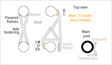
This other arrangement of keys at the boot of the baritone oboe of Sep 16, 2018 has advantages: Pyramidal frames hold the boot firmly together so the keys fit precisely. Transmissions from the main joint are easy and the disassembled main joint protects them. The keys can be light and still stiff. The keys are easily synchronized and adjusted. The toneholes can be tilted so the covers move perpendicularly to them. Not displayed here. With easy adaptations, the arrangement of keys applies to similar instruments if designed with a boot. This includes the English horn, lower tárogatók, saxophones, rothphones, sarrusophones, optionally with my automatic cross-fingerings. Marc Schaefer, aka Enthalpy
-
I put thoughts in the liquid hydrogen tank because compressed hydrogen needs a tank too heavy. Also, liquid hydrogen is less dangerous than compressed one.
-
Hi Frank, thanks for your interest! Thermal engines tend to be less efficient than the fuel cells' 60%, but they improved quickly in the past two decades, and the difference is small now. As thermal engines are much lighter than fuel cells, the alternative must be considered, sure. 600kg less would sell 6 seats more, big difference. Hydrogen is difficult to bring to a combustion chamber. Injected liquid in a piston engine prior to compression, it freezes air's water vapour and possibly the carbon dioxide, and as hydrogen vaporizes, the extra volume to be compressed spoils the engine's efficiency. Injected gaseous and lukewarm in a piston engine prior to compression, the extra volume to be compressed spoils the engine's efficiency. Still bad. Injected gaseous after compression is as bad as before compression. Injected liquid after compression is the least bad option at a piston engine. Hot air components won't freeze, and this squanders the least power. However, it demands a damn strong injection pump, much worse than the difficult pump of a common Diesel engine, and the whole pump and circuit must work at 20K. Design is badly difficult AND operations get complicated, as the whole circuit must be cooled before start. In a turbomachine, hydrogen should be injected after air compression for the same reasons, but this demands a pump much more powerful than now, and again pre-cooling before starting the engine. I put there http://www.chemicalforums.com/index.php?topic=91121.msg325955#msg325955 (log in to see the drawings) and especially this message for hydrogen alone http://www.chemicalforums.com/index.php?topic=91121.msg333549#msg333549 some pumping cycles with the necessary power, and they inject the hydrogen already hot in the chamber, which helps stabilize the flame. Meant for ramjets and scramjets but fit turbomachines too. It's more rocket than aeroplane technology, and hasn't been developed for airliners up to now. Understand: long and costly. Simpler cycles are possible with turbomachines. Hot output from fuel cells: the 40% wasted energy must go somewhere, yes. My doubt is: how heavy is a heat exchanger to make use of this? Each time I tried, heat exchangers were too heavy to outperform alternative solutions. And if you can operate the fuel cell at a pressure higher than the chamber of the thermal engine that uses the waste heat, to inject the fuel cell outlet in the chamber without a heat exchanger, then you must first pump the air and the hydrogen to that pressure, which is nearly as bad and pretty complicated too. The rest is less of a problem, for instance hydrogen combustion is already known from the more difficult scramjets.
-
20 to 30 passengers, said Norway's minister, and 90 minutes electric flight. Here you are, with fuel cells, not batteries. It takes limited development, essentially the superinsulated tank I described earlier. The fuel cells exist at least for cars, the motors are nearly banal. With the main gear at the fuselage and engine nacelles under the high wing, the Dornier 328 adapts to fuel cells easily, and its size fits better than the ATR-42. de.wikipedia and (other variant) en.wikipedia Can just the nacelles be retrofitted? 2*1400kW need 2*700kg fuel cells with the Toyota Mirai's performance en.wikipedia Estimated energy needs: 262kg liquid hydrogen in two ellipsoids D=0.9m L=4.6m. 2.2MW*5400s Flight 1.0MW* 600s Taxiing 1.6MW*1000s Divert 100nm @540km/h 1.4MW*2700s Waiting to land Zero Descent compensates ascent? ---------- 17.9GJ Energy at shafts 31.4GJ Chemical energy in 130kmol *60% *95% The motor is a ring D=0.8m gap and nearly 0.2m length, because gears need maintenance, can fail and they weigh too. With some 2*30 poles and sine three-phase, each motor weighs 250kg roughly. This is the estimated mass change from kerosene to hydrogen: -800kg Two turboprops +500kg Two electric motors +1400kg Fuel cells -1300kg Kerosene +260kg Hydrogen +250kg Two hydrogen tanks ---------- +310kg Keep the airframe, take 3 or 4 passengers less. 32 had too little room anyway. The hydrogen and its tanks being so light, more range is seducing. Extra-silent propellers would make sense. Marc Schaefer, aka Enthalpy
-
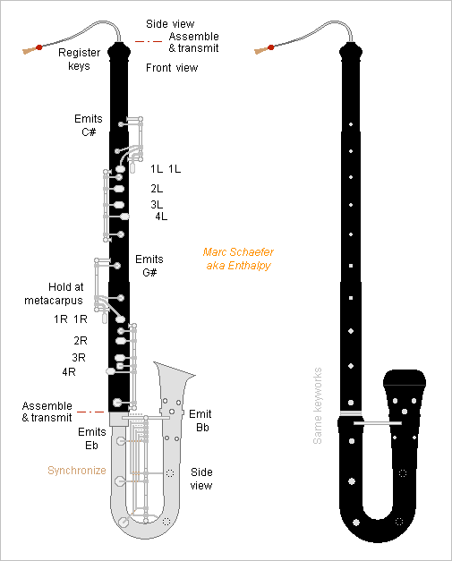
The variant I sketched on Jul 30, 2017 of the even fingerings for oboe and similar http://www.scienceforums.net/topic/107427-woodwind-fingerings/?do=findComment&comment=1004315 makes simple keyworks. Experiments shall decide, but trying to imagine their use, I feel them as convenient as the other variants. So here is a fingering chart for this D variant: Register keys are not displayed. Their number and range must be experimented. Double them at left and right thumbs like the low notes. The cross-fingerings are only indicative for an oboe. This fully flexible system adapts to the instrument and extends to high modes. Marc Schaefer, aka Enthalpy ==================== This D fingering variant fits very well a bass or baritone oboe, which is a tenor written like the usual soprano oboe but sounding an octave lower, which must give it over three octaves range. Baritone oboes are presently built straight, possibly because specialized oboe luthiers don't make brass bodies. The instrument stands on the ground, and small musicians need accessory to play sitting. I prefer the older shape resembling a bass clarinet. Electrodeposition of silver, copper, nickel... alloys needs little skills and can make the boot and bell including all protruding holes. Or filament winding can make them of stiff and thick material. Usually done by a subcontractor's machine. Or plastic injection. ABS and PP are used presently for instrument bodies, polyketone should be tried, loading with choppers would make them stiffer. Needs an expensive machine at a subcontractor and an expensive mould. A separable bell can use other materials than the boot, for instance wood. The sleek folded design is as big as a tenor saxophone and fits in a smaller bag if the boot is separable. Carried with a harness, it's played sitting or standing. One or two crutches free the thumbs like on the bassoon. The boot could turn earlier and more sharply than sketched, but not as sharply as historical instruments. The bocal can replace some body length if the saved material pays the added transmissions to the register keys. Add a loop in the bocal for antique look. Instead of a pear, whose sound is boring and differs too much from the soprano oboe, I prefer a narrow bell with the extra holes added by Stowasser to the tárogató. I've sketched two stages of them. Their distance to the bell opening doesn't scale as the body length. The boot's covers have similar arms lengths and rotate around a single axis, which simplifies their synchronization as already described http://www.scienceforums.net/topic/107427-woodwind-fingerings/?do=findComment&comment=999559 For stiffness, I'd have an X, or better two pyramid frames, whose apex also holds the end of the axis. The transmissions to the boot need no big accuracy. The sketch shows the boot and bocal's side but the main joint's front. Keyworks for the thumbs were already shown on Jul 30, 2017. On this tenor, the front fingers need covers, with simple keyworks. The many transmissions between the thumbs suggest a single main joint about as long as on a bassoon: as grenadilla gets rare, filament winding is an option, or machined polymer, maybe polyketone, preferibly loaded with choppers. I dislike cocobolo's sound and suppose maple wouldn't fit here. The double-reed instrument needs narrow tone holes and chambers https://www.scienceforums.net/topic/113115-intentional-losses-in-wind-instruments/?do=findComment&comment=1035629 whose cutoff frequency doesn't scale like a tenor but stays at 3 to 4kHz https://www.scienceforums.net/topic/113243-sound-perception/?do=findComment&comment=1037471 and next Most of this applies to English horns too. Marc Schaefer, aka Enthalpy
-
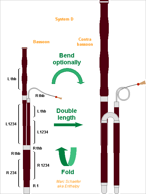
The bassoon's system applies nicely to the contrabassoon. With the left hand controlling the tenor and bass joint, the right one the boot, and few transmissions between all joints, the boot can be split in narrow and large joints and easily folded upwards. With all joints nearly as long, this makes a more compact fagotto. It's one folding more than the usual Heckel system contrabassoon, whose tenor joint begins at the bottom. The four first joints stay permanently together. The bell can be bent and run downwards like on the Heckel system for a smaller instrument. Or, as depicted, it can be straight and assembled to play: More compact transport case. Contrabass taller than the bass in the orchestra, ah. Resembles more a bassoon. Needs only wood knownledge from luthier and workshops, especially if all tone holes fit on the wood sections. I believe electrodeposition can make all bends and the bocal, if needed the bell, with little skills http://www.scienceforums.net/topic/111316-woodwind-materials/?do=findComment&comment=1031427 It can also make wide stiff tubes for the keys with reasonable weight. Per carbon filament winding or of possibly reinforced polyketone, all joint walls can be single parts. Marc Schaefer, aka Enthalpy
-
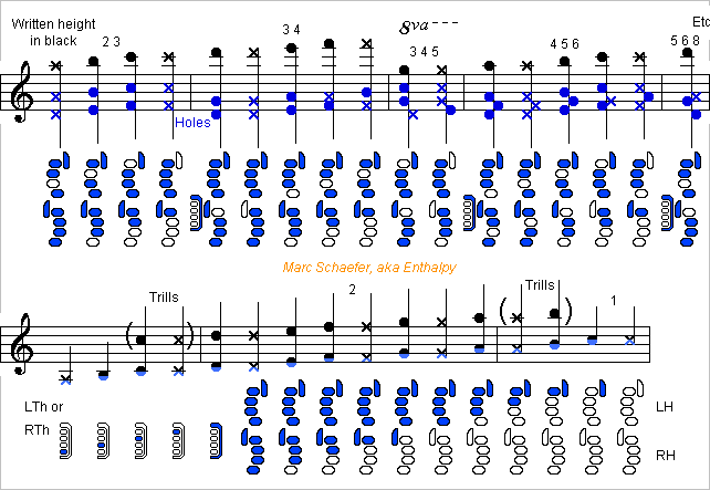
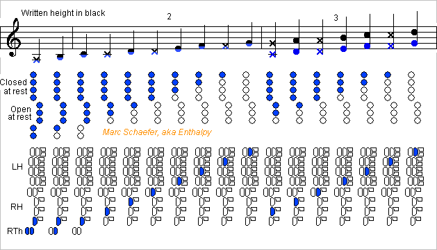
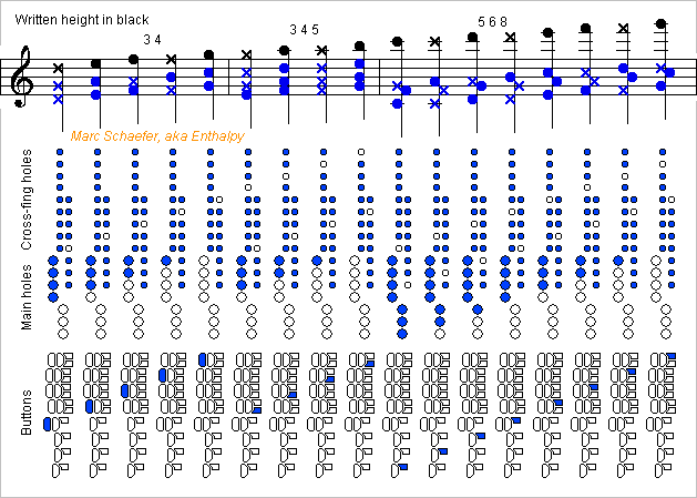
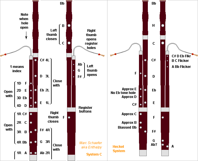
Because the soprito starts on the 2nd one and uses many higher modes, automatic cross-fingerings would be difficult. But here is a system to ease cross-fingerings for the soprito. Here 7 main holes achieve 8 notes, enough to join the modes, as these are high hence close to an other. The 7 main holes begin on C because an instrument's lowest notes tend to overblow abnormally, so the right thumb makes B and Bb. In the present system, a single front finger presses a key to move several main holes and define a note. The four upper main covers are closed at rest and the left fingers open one to four, while the three lower main covers are open at rest and the right fingers close one to three. The right index moves no main cover but can have a dummy button as sketched. The holes and the buttons are displayed separately on the sketches. Synchronisation hardware was suggested there http://www.scienceforums.net/topic/107427-woodwind-fingerings/?do=findComment&comment=999559 The musician presses only one button at a time as on a piano, excepted for the low B and Bb. This is easier than usual cross-fingerings. No alternate fingering nor trill key is foreseen. Extra buttons open one or two additional cross-fingering holes. Adjacent buttons can share the same cross-holes for different modes chosen purposely, so two sets of cross-holes suffice: Mode 1 isn't used by the Soprito. The narrow bore and the reed's size stabilize the mode 2. A register hole isn't excluded. Mode 3 reuses the same main holes as mode 3 with a register key. Mode 3 4 opens a cross-hole a fourth (5 semitones) higher than the highest open main hole. Mode 3 4 5 opens two cross-holes, a major third (4 semitones) and a major sixth (9 semitones) higher. Mode 6 isn't used. Mode 7 isn't used. Mode 5 6 8 opens two cross-holes, a fourth (5 semitones) and a minor sixth (8 semitones) higher. The system opens cross-holes 4, 5, 8 and 9 semitones higher than the highest open main hole, but adjacent main holes share cross-holes: a key for 4 and 5 is common to two adjacent main holes, a key for 8 and 9 too. The left index opens 4 main covers and 0 to 2 cross-covers. The right pinkie closes 3 main and may open 2 cross-covers. Narrow covers like at the oboe linder this drawback. The sketches show extra buttons that act on the main and cross-covers to help the musician. They need little extra local hardware. Without them, the musician would press simultaneously with the main cover 1 or 2 separate buttons linked directly with the cross-covers. Separate cross-covers ease the design of a well-tuned instrument. Register keys are not displayed. Probably at left thumb. One stabilizes mode 3, maybe an other suffices for modes 3 4 and 3 4 5, and still an other for mode 5 6 8. A sketch of the keys may come, perhaps. Marc Schaefer, aka Enthalpy
-
I have doubts now that the piccolo woodwind can have a single reed as depicted on Nov 06, 2017 http://www.scienceforums.net/topic/107427-woodwind-fingerings/?do=findComment&comment=1021947 because the reed's susceptance destimated as on Dec 03, 2017 http://www.scienceforums.net/topic/112039-woodwind-reed-susceptance/?do=findComment&comment=1026941 remains big even with an Ab clarinet reed. The clarinet's cylindrical bore is wide near the reed, whose susceptance shortens the air column reasonably. A saxophone (soprillo) is wide and plays the high notes only by the second mode, so hole positioning can correct the intonation. A single reed would shorten a narrow conical bore possibly too much, more than a quarter wavelength. Only a double reed, uncomfortably small, would fit. I may provide figures some day.
-
The Norwegian government wants electric airliners for all flights under 90min in 2040 bbc.com and dailymail.co.uk In 2018, I see how to fly for 90min with batteries, but to divert to an airport 100nm away then wait 45min in the air, as safety demands, a plane doesn't resemble a profitable airliner. With liquid hydrogen and fuel cells, such a design is easy. The Atr42-72 modification I described on Apr 18, 2013 scienceforums.net does much more than that.
-
Existing bassoons, both with French and Heckel systems, have extremely long tone holes, more so nearer to the reed. The common explanation, that the biassed long holes reached the proper positions at the air column when keys were expensive, is insufficient because presently we could have more keys and because these very inductive holes are a semitone to a tone higher at the air column than where pressure nodes should be. Instead, the bassoon needs the inductance and loss of the holes to soften the throat notes, more so due to the double reed and the huge first register. Also, musicians are used to the resulting illogic fingerings, especially at high registers. Anyway, these abnormal holes disturb the high register. If they are 60mm long (I don't have my bassoon here), that's lambda/4 for 1450Hz, the second harmonic of the conventional highest F#, so closed holes attenuate strongly the harmonics of the high notes and hamper the fundamental above the conventional G. Open holes don't act as a short-circuit neither, nor even as an inductor, but as an open-circuit near the lambda/4 condition. I'd like to get rid of these long holes if possible. Some notes do it already, for instance the C# at the end of the tenor joint. A new system is the opportunity since it changes the fingering anyway. I did not write "wide short holes at node positions" because this does not fit a double reed - and not even the clarinet and tárogató do it. But make the tone holes quite shorter than presently, and narrower to keep some of the inductance, the loss, or a bit of both (they are incompatible). I suppose that this array of holes makes the bassoon's 500Hz "formant" when not used in cross-fingerings. I want to give general explanations and figures some time. The oboe's chambers are an interesting option on the bassoon to soften the sound https://www.scienceforums.net/topic/113115-intentional-losses-in-wind-instruments/?do=findComment&comment=1035629 the absorbed band shall not be scaled to the bass instrument but still start at 3 to 4kHz to fit our perception https://www.scienceforums.net/topic/113243-sound-perception/?do=findComment&comment=1037471 and next which needs a small diameter ratio. Marc Schaefer, aka Enthalpy
-
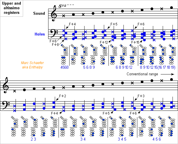
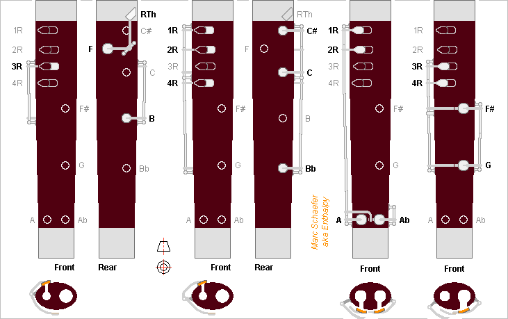
In the bassoon system I described here, the biggest difficulty for the musician in the first two registers is switching between them: open the left hand, press the register button, move the right fore fingers but open 4R and possibly 3R, all simultaneously. I tried to simulate it and found quite easier to press the register key when the right fore fingers move toward the wrist. The present system D does that: versus system C, it swaps the proximal and distal buttons at the boot. The tentative cross-fingering chart follows simple flute logic, so it's inaccurate for the bassoon; a design goal could be to let them sound all a semitone higher. The chart shows that the system provides flexible cross-fingerings that seem easier to play than on the Heckel system. Most bassoonists can play higher than the conventional G, so I added a chart for an altissimo octave but dropped the alternative fingerings. At C# and above, the fingerings get more complicated because I arbitrarily opened four holes above the main transition. At E and above, emission gets free help from many holes at the main transition, because this system opens them all and they are properly aligned as modes 15, 16, 17, 18, 19, 20 to reinforce the wave reflection. The other joints are kept from the system C and I swapped the fore buttons at the boot. Redundant views with few keys each make it legible. The sketches are not accurate to the pixel, and the holes' positions will evolve. An instrument designer would find shortcomings and improvements. At least, the simplicity is patent. Here too, the right thumb operates register keys at the tenor joint, so the right hand is high in this option. Maybe single tilted parts can connect the buttons to the Ab and G covers. The long keys for A and Ab holes should be wide for stiffness; electroformed tubes could be lighter, as suggested there http://www.scienceforums.net/topic/111316-woodwind-materials/?do=findComment&comment=1031256 Marc Schaefer, aka Enthalpy
-
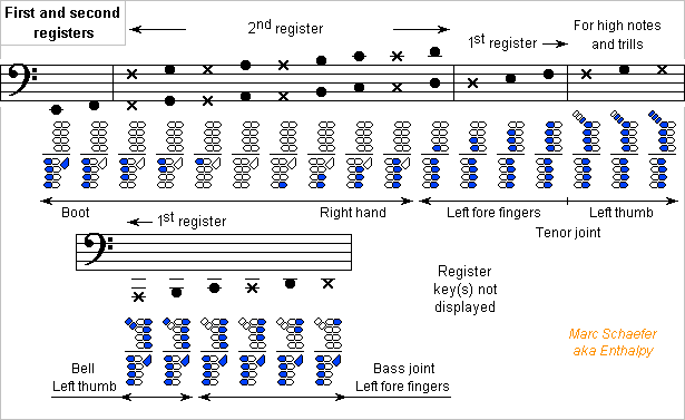
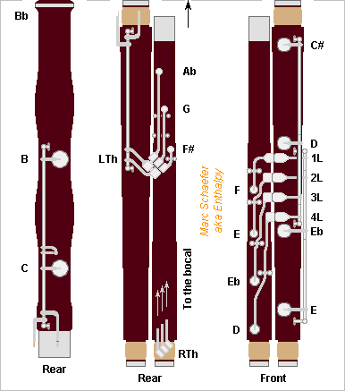
Here is a keyworks example for the bassoon with system C described on May 01 and 03, 2018 https://www.scienceforums.net/topic/107427-woodwind-fingerings/?do=findComment&comment=1050880 and outlined on Aug 18, 2018 https://www.scienceforums.net/topic/107427-woodwind-fingerings/?do=findComment&comment=1065554 Using preferably the button arrangement proposed on Jul 14, 2018 https://www.scienceforums.net/topic/107427-woodwind-fingerings/?do=findComment&comment=1060629 If someone develops this instrument, the positions of the holes will vary, the length of the joints possibly too, hence the design of the keys. Some tone holes are now at the rear, better than behind hands. Because my drawing capabilities were exceeded, I've changed again the positions of the proximal and distal buttons at the fore fingers: here the buttons that open higher tone holes are on the right, and the ones that close lower tone holes on the left, at both hands. In other words, the buttons are at the same side as the air column. Keys with long vertical shafts are not the usual choice at the bell. All buttons are spread comfortably. Small bassoonists will like that, older ones with arthristis too. Both hands are slightly higher than on the Heckel system, also nice to small musicians; that's mainly because I wanted the right thumb to operate register buttons hold at the tenor joint, but I ignore how useful they are nor how many there should be, and a transmission from the boot is possible too. The register keys must reach the bocal, but I didn't represent this on the sketch. The right side of the tenor joint is available. Register keys at the bocal are nothing new; I suggested shapes on May 13, 2018 https://www.scienceforums.net/topic/107427-woodwind-fingerings/?do=findComment&comment=1052574 This system makes keyworks much simpler than the Heckel system, and simpler than the French system too. It will be more silent too, as most keys consist of one button and one cover linked permanently. Marc Schaefer, aka Enthalpy
-
In the bassoon sketch of Aug 18, 2018, please read 1L 2L 3L 4L instead of 1D 2D 3D 4D.
-
Or rather, keep both joints as on the Jan 02, 2018 sketch, as well as the covers and fingers positions, but split the raise key for the left hand joint and add a transmission, so that the button and its articulation stays with the right hand joint at disassembly, and the rest of the key with the left hand joint. Marc Schaefer, aka Enthalpy
-
At the clarinet with even fingerings sketched on Jan 02, 2018 http://www.scienceforums.net/topic/107427-woodwind-fingerings/?do=findComment&comment=1031551 one raise button juts far out of the upper joint to be operated by the right thumb. The upper joint can be made longer and the lower shorter, so the holes operated by the right index are at the upper joint. Their covers may be articulated at the body's right side. Then both raise buttons stop about where the joints do and are less exposed. Alternately, one raise button can move the keys for the upper and lower joints, and the transmission be made at the border. It needs an adjustment. Marc Schaefer, aka Enthalpy
-
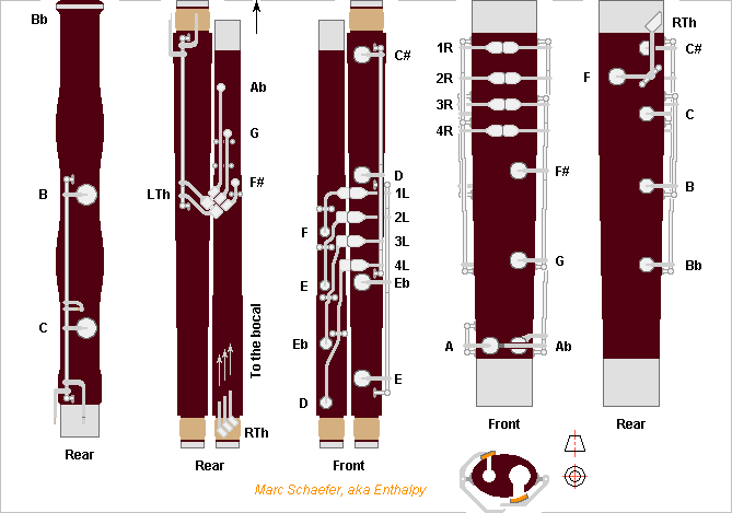
Here's a possible aspect of a bassoon with the system C described on May 01 and 03, 2018 with two buttons per fore finger https://www.scienceforums.net/topic/107427-woodwind-fingerings/?do=findComment&comment=1050880 The tone hole positions are approximative. Up to A they're deduced from the low holes, from Bb to C# they drift progressively up to a semitone higher as they get narrower. I'd not make the holes as long as on the French and Heckel systems since this must hamper the highest notes: just shorter and a bit narrower to keep the losses. The hole positions I indicate at the bore for the Heckel system are eye estimates. As my system opens all holes below the main transition, the holes are regularly spaced, and the intonation and emission hopefully even. Few transmissions are needed. The left fore fingers open holes at the tenor joint and close others at the bass joint, each joint carrying only its own keys. The right fore fingers open and close holes at the butt only. The left thumb opens one of three tone holes whose keys reside fully on the tenor joint, as inspired by Heckel's overblowing keys, or closes one or two tone holes at the bell, needing transmissions from the bass joint. The right thumb closes locally a tone hole or opens one of several register holes at the bocal whose buttons may reside at the tenor joint, needing transmissions. My system frees early the right thumb, which can operate several register keys high on the bocal, to make high notes hopefully easier, stronger, and with nicer sound. I could keep the bassoon's nice shape, size and aspect. The boot is little longer to turn between A and Ab, whose holes may be slightly biassed to the bottom. Turning between Ab and G is an alternative. The C# hole is at the boot, but the hole and key could be at the tenor wing and the right index still move it. The F hole and key could also be at the bass wing if accessible to the right thumb. The tenor joint doesn't go as high, the bocal length and shape compensate that. Or give the left thumb a fourth tone hole there, if it provides an advantage unseen by my tentative fingering charts. I've drawn the C hole at the bell so all parts are equally long for a smaller case. Though, manufacturers use to prefer a longer bass joint and save a transmission. The keyworks seem much simpler than on existing bassoons. I may give sketches some day. The key arrangement I proposed is thought for this bassoon first: https://www.scienceforums.net/topic/107427-woodwind-fingerings/?do=findComment&comment=1060629 Fingerings look easier for the two first registers, and cross-fingerings for the higher registers may be easier and should be more efficient. If the sound and emission are more even too, my system would be an improvement. But it needs a lengthy development due to the double reed imposing narrow tone holes. Marc Schaefer, aka Enthalpy
-
Mass estimates for the 2015 BZ509 mission to bring samples back. An Atlas V 551, Ariane V, Ariane 64, H-IIB puts 18800kg on a naturally inclined 400km low-Earth orbit. The payload volume demands a bigger fairing, or an own stage, or the whole mass could be reduced. According to the escape script of Jul 27, 2014 http://www.scienceforums.net/topic/76627-solar-thermal-rocket/?do=findComment&comment=818683 Eight D=4.57m sunheat engines bring 14503kg to 127Mm apogee with adequate tilt in about 17 months. Or add engines, 30 kg each. A small O2+H2 engine gives 4233m/s over Earth's gravity and speed to 11450kg. If accounting tank masses, the mass optimum would be over 4233m/s, and exceeding this new optimum would save volume. 890kg of O2 and shared H2 tanks and 301kg engine are dropped, leaving 10259kg. A 25kN engine with fuel cells and electric pumps would outperform the RL-10. The eight sunheat engines bring 5042kg to 13058m/s over Earth's gravity and speed in 33 days. The tank for 5.2t H2 is dropped, leaving 4108kg heading to Saturn in 2.3 years. The optional own stage can stop here or already after escape. I take 182kg per ton of H2 for insulated balloon tanks in trusses that carry a heavy load during launch. Dropping the trusses earlier, for instance with the O2+H2 engine, is uneasy but would save mass. Here I neglect the 2.5° inclination of Saturn's orbit, but it could cost up to 1.8km/s. The Saturn flyby is for free. Hohmann transit to BZ509 at 3.18AU perihelion takes lengthy 8.6 years. Tilting from 180° to 163° takes approximately 3856m/s. Eight sunheat engines optimized for about 6.7AU need 1.2 year to eject 1345kg. The chambers may differ from the ones used at 1AU, which adds few unaccounted kg, but then 100kg of 1AU chambers would have been dropped before. Four 30kg engines and 245kg tank are dropped, leaving 3332kg heading to BZ509. Four engines brake by 1331m/s in 190 days because dice limit the sunlight to the power available at 6.7AU. A shorter trip would need more fuel mainly here. 2993kg arrive at 2015 BZ509 full of nice tools and toys. I take Saturn at aphelion, BZ509 at perihelion when arriving and at aphelion when leaving. Lengthy orbits don't let choose, and I didn't check the consequences of BZ509 being far from its nodal points. ========== Of the 2993kg, 300kg are a return capsule, 100kg a bus for the return leg, 100kg are four sunheat engines kept for the return, 110kg the tank with 236kg H2 for the return and 339kg already used upon arrival. The other 2147kg comprise 400kg of bus and 1747kg to split among remote sensing and landers. Some robotics catch the landers and transfer the samples. As I suggested elsewhere, remote sensing could include a pulsed laser powered by the sunlight concentrators, hydrogen and xenon jets to erode the surface, a hydrogen gun for deeper sensing, maybe tethered hollow harpoons to take samples without landing. I'd prefer several landers of different construction for redundancy: landing, anchoring and sampling hardware... The size, shape, mass and composition of BZ509 are unknown. Reflection suggests D=2km, then iron-nickel would weigh 3*1013kg. Take-off would need 2.2m/s provided by springs, possibly hydraulic, and the ferry might orbit below R=3.5km but its sunheat engines couldn't levitate it. But if BZ509's mean density is 500kg/m3, the Lagrange point is at R=0.9km, so no orbit is possible. As with Chury, staying near BZ509 is difficult, until someone has an idea. Between the nodal points, the mission has 5.8 years to take probes, optionally more for remote sensing. ========== 858kg leave BZ509's vicinity. The four sunheat engines use 236kg in 148 days at 7.09AU to brake by 4000m/s within the retrograde orbital plane to join Earth directly. If I misunderstood and detilting by 17° is needed, the sunheat engines still achieve it, but the capsule must be half as heavy and the leaving aggregate twice as heavy. Not the hypothesis here. Not forgetting the fuel for fine-tune would be better. The bus, engines and tank separate from the 300kg capsule that re-enters Earth's atmosphere at 68km/s. A capsule has to decelerate by ~500g or it would exit the atmosphere, ouch. Some flat form for L/D=1, if feasible for that speed, would reduce it to 74g downwards and backwards, or total 105g. The 300kg capsule comprises: 146kg heat shield 24kg parachute 80kg bus 10kg sample boxes, as there http://www.scienceforums.net/topic/85103-mission-to-bring-back-moon-samples/?do=findComment&comment=823276 40kg samples of extrasolar matter for the Earthlings' labs. Marc Schaefer, aka Enthalpy
-
And if I pay more attention to the text accompanying the research paper's images (I don't have the full paper), then I write fewer pointless comments... Erratum and comments to my message of July 15, 2018 6:40 pm... The paper does not tell that calcite doubles its susceptibility upon heating. It's clay. A clay sample from that location more than doubled its susceptibility "upon heating". Doubling can't explain the measured magnetic anomalies. Maybe the temperature was too low: Kostadinova-Avramova and Kovacheva observed a much stronger effect at 700°C than 400°C. The effect results from permanent magnetization much more than from increased susceptibility. The same clay sample can be re-heated to 700°C for new measures. The irregular black colour, especially on fig.3, resembles char by a fire, and spectroscopic analysis confirmed. The authors carefully dated several fires to an age compatible with the artefact itself, that is, with a few thousand years accuracy. A previous study by C-14 had found a fire much more recent. Dating by the growth rings at calcite has already been used. I would find hard to believe that the orange or brown colour results from fire: too uniform. Clay incorporated to calcite looks better to my (untrained!) eyes. The more recent stalagmite on the artefact is white. Chemical analysis would tell better if the orange calcite incorporates clay. Comparison with other near locations in that cave would indicate whether that colour was brought by a flood, by temporary changes in the stalagmite formation, or by human action. I haven't seen whether the orange colour reaches deep in the stalagmites or is superficial. Clay samples from hearth and from nearby locations in the cave would usefully have a known orientation, to compare their magnetization with the observed perturbation, before and after new heating.
-
Sure. Failed designs show much bigger examples at Olkiluoto, Flamanville, Tianshan and next Hinckley Point. What I like less at explanations by failed attempts is that they offer so many variants that they can explain anything. Or if you prefer, they are not refutable. It does not mean that they are wrong, only that reasoning on them is virtually impossible. This is a seducing interpretation, but it has some difficulties. Why go so deep in the cave? 50m would suffice, they walked 300m from the entrance in a difficult terrain. That's dangerous and lengthy. For a safe water supply available only there, I'd do it. To sleep comfortably, I'd prefer a nearer location. The artefact is (at least today) in a location low and inundated. That's where I would not put my camp. The "walls" follow contours of constant altitude. Perfectly justified for a reservoir, while a camp wall would have straight walls where the terrain drops. Traces interpreted as fire remnants are everywhere, including on the "walls", rather than at the centre. Their skull volume exceeded our. But so does elephants' skull too. The surprise to archaeologists is that they had seen no construction by Neanderthals prior to this one. And what is intelligence? Intelligence is specialized. My cat was intelligent to interact with humans and exploit us, but he never made something with an object, except if the object represented a prey. He wouldn't even carry an obstacle away from his bed. Bruniquel is the first time archaeologists find indications of Neanderthals going deep in caves. 175,000 BP was during a cold period, yes https://en.wikipedia.org/wiki/Ice_age Good point, the problem of wood transport. =========================================================================== The human bones in Jebel Irhoud, presently attributed to Sapiens Sapiens, were dated to 300 000 BP in 2017, that is, after the paper about the artefact in Bruniquel. https://fr.wikipedia.org/wiki/Djebel_Irhoud https://en.wikipedia.org/wiki/Jebel_Irhoud This half-opens the alternative possibility that Sapiens Sapiens made the artefact in 175 000 BP in Bruniquel. No evidence exists of Sapiens Sapiens in Europe at that time. From now-Morocco to now-France, humans would have needed to cross the Gibraltar straights (deep water during the ice age too). But few years ago, archaeologists saw only Neanderthals in Morocco at that time. They may change their mind for Europe too. So what's more difficult to accept: first evidence of Neanderthalensis making artefacts deep in caves, or first indication of Sapiens Sapiens in Europe at that time? Please take with mistrust, as here I'm very far away from anything I imagine to understand.
-
At Bruniquel cave's artefact, the paper's authors recorded a strong magnetic gradient that excludes many origins. The data is mapped on fig. 5 with explanations http://www.nature.com/nature/journal/vaop/ncurrent/fig_tab/nature18291_SF5.html (it was there) they saw +-12nT/m at several places, up to +-24nT/m. I didn't see the measurement altitude and suppose it was 1m over the flat bottom, maybe 0.5m over the construction's peaks. The apparatus takes the difference between two Geometrics G858 sensors http://www.geometrics.com/geometrics-products/geometrics-magnetometers/g-858-magmapper/ which measure the total induction by caesium vapour cells and are stacked vertically with 0.22m separation, so "gradient" means the vertical gradient of the total induction. ---------- I compare with what a small magnetic dipole achieves: the strongest case is the polar component in the polar direction, B = 2*10-7mR-3 where m is the magnetic moment in A*m2, B in Tesla, R in m http://www.phys.ufl.edu/~acosta/phy2061/lectures/MagneticDipoles.pdf https://en.wikipedia.org/wiki/Magnetic_dipole grad(B) = 6*10-7mR-4 (put signs as you like) 24nT/m would need 2.5mA*m2 at 0.5m or 40mA*m2 at 1m - or half as much for 12nT/m. We can already note that today's best permanent magnets of FeNdB provide 1100kA/m, so at 1m such a supermagnet would need to be 2mm3 big. ---------- The magnetic susceptibility X of the artefact's materials deform the geomagnetic field, but how much of which materials does it take? At Bruniquel, the total geomagnetic induction is 46µT, tilted 58° from the horizontal https://upload.wikimedia.org/wikipedia/commons/f/f6/World_Magnetic_Field_2015.pdf https://en.wikipedia.org/wiki/File:World_Magnetic_Inclination_2015.pdf and the total geomagnetic field 37A/m. I take everywhere SI conventions, where X is dimensionless and 1+X is the relative permeability µr: Induction B (T) = (1+X)µ0H (H field in A/m) with µ0=4pi*10-7 by SI definition A volume L*S of material with susceptibility X lets pass the same induction as vacuum if we add a current H*X*L around it and then the external distribution is the same as for vacuum. This current has a moment H*X*L*S proportional to the item's volume. And since the added current compensates the item's presence, the item has the same external effect as the added current without the item. Yes, this can be done better. An algebraic solution exists for a sphere, and by packing spheres of varied radii, we can fill any shape. Put signs as you prefer. The added current depends rather on the reluctance which varies with 1/(1+X), so for big X at ferromagnets the computation differs. Now, the far effect of a small dipole is proportional to the magnetic moment, so for any small distant shape with uniform susceptibility X, only the volume counts. The item acts by m (A/m) = H*X*V, and if the item isn't small, integrate this with varying distance. If the item were magnetically soft iron, (0.1m)3 at 1m would make the observed 24nT/m. Wow! ---------- How much? Let's take arbitrary 1dm3 of materials with X=10-5 at 1m. In the 37A/m geomagnetic field, it's equivalent to a dipole of moment m = 370nA*m2 that creates a gradient of 0.22pT/m. For the materials expected at the artefact, some experimental X are: http://www.irm.umn.edu/hg2m/hg2m_b/hg2m_b.html https://en.wikipedia.org/wiki/Magnetic_susceptibility -0,9*10-5 Water -1,3*10-5 Calcite (CaCO3) +2,7*10-4 Montmorillonite (clay) I had suggested here on 31 May 2016, 09:59 pm that the mere height of the contruction could explain the magnetic perturbation. But even 20dm3 of calcite at 0.5m create only 0.07nT/m. Wrong! The authors observed that calcite's X doubles after heating in a fire. But 1dm*6dm*6dm of heated calcite at 1m create insufficient 0.02nT/m. Raw clay has a bigger X that varies much with the iron contents. Taking 27*10-5 for 1dm*6dm*6dm at 1m explains 0.2nT/m, still 100* too little. Clay heated by fire has a stronger effect. From M. Kostadinova-Avramova and M. Kovacheva https://academic.oup.com/gji/article/195/3/1534/622882 table 3 their most reactive sample, heated to 700°C and cooled in 50µT, has a susceptibility as above essentially, but also a permanent magnetization of 22A/m if I read properly, almost as strong as the geomagnetic field. 0.05m*0.2m*0.2m of this heated clay suffice to create 24nT/m at 1m. Or (50mm)3 at 0.5m. ---------- Maps of the gradient at different heights would let infer the altitude of the cause. It's an inverse problem, difficult to solve and with many solutions, needing some assumptions like "isolated small sources". I'd be glad to know how much clay was available in this cave, and whether the artefact accumulates abnormally much of it. And whether bare calcite from this site gets the observed colour from mere heating, or if it needs to absorb clay. R=50mm get hot to the centre in 2min only: are the stalagmites brown to the core? My gut feeling is that the colour is too uniform for a fire, I imagine a prolonged contact with clay more easily. Or could water drops bring the clay too? Marc Schaefer, aka Enthalpy
-
Some fingerings and keys systems I proposed need two buttons at some fingers, notably for the bassoon. I had suggested to operate the buttons at different phalanges. The fingertip could also slide between the buttons. If bending the finger suffices thanks to the relative positions of the buttons, this movement may be easier and faster. Experiment shall decide. On the sketch, the proximal button is higher than the distal one and rounded, so the finger slides to it more easily, over its natural slope, and can descend to the distal button. At least at the thumb's buttons of existing bassoons, I prefer no rolls. The oboe, contrabassoon and many woodwinds have small covers and displacements, but the proposed arrangement may not fit a baritone saxophone. Or is it less bad than presently for the saxophonist's right pinkie? Marc Schaefer, aka Enthalpy
