Enthalpy
Senior Members
-
Joined
-
Last visited
Everything posted by Enthalpy
-
Err, did I possibly maybe write tr-tf in this thread? I had meant tplh-tphl. It shouldn't happen. Sorry.
-
Being known to make more silent gears than polyamides and polyacetals, polyketones could make more silent keys for wind instruments. Pushrods at rotary valves, transmissions between keys and plain bearings at woodwinds often use polymer parts, which polyketones hopefully improve. At the bassoon and also the oboe, it would be needed. Marc Schaefer, aka Enthalpy
-
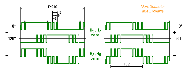
Here's the aspect of the waveform with T=210 a=5 b=14 c=16 from Mar 04, 2018 9:05 pm. Adding two of them with 60° lag or subtracting them with 120° gives the same wave. Electric motors sometimes run slower: at start on an electric plane, more often on an electric or hybrid car. The same waveform and filter would then drive the motor with a jagged voltage, but the drive electronics can use the same power components in PWM mode when running slowly. For an electric motor, a counter with fixed frequency suffices to place the transitions. Maybe a fast microcontroller can create the waveforms directly from its clock, or the controller tells the dates of the coming transitions to comparators that refer to one fast big counter. This can be integrated on a special chip, optionally the same as the controller. Marc Schaefer, aka Enthalpy
-
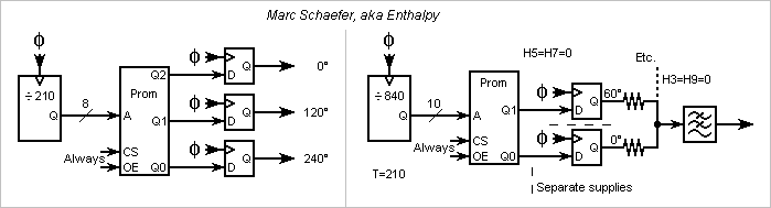
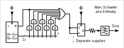
On the right side of the last message's diagram, I suggested separate supplies for the output flip-flops. While it can be useful to filter individual supply lanes for the flip-flops (in separate packages with LC cells), the phased outputs attenuate the target harmonics only if the supply potentials match very accurately, and this is best obtained from a common regulator.
-
The quick machines need AC in the kHz range, and sometimes MW power. PWM inverters are then difficult. I had suggested to provide square voltages rather than sines to reduce the number of lossy transitions per cycle http://www.scienceforums.net/topic/73798-quick-electric-machines/?do=findComment&comment=736205 but now there is an alternative, with my waveforms that suppress harmonics using few transitions. In the thread "quasi sine generators", for instance there https://www.scienceforums.net/topic/110665-quasi-sine-generator/?do=findComment&comment=1041409
-
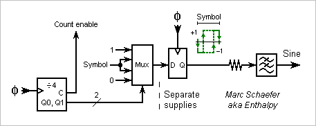
The stone-old Proms like 2716 make the waveforms easily, as they receive all addresses at once on pins distinct from the data. They are still available in small amount. I didn't check if more recent components exist nor how they are addressed. Of the diagrams, the left example provides the drive signals for a three-phase power stage driving a motor, a transformer and transport line... The Prom behaves statically, so a counter and a set of flip-flops suffice. One of the eight output bits defines each waveform, possibly more than three to stack transformers. Only the switching losses in the power components limit the number of transitions per cycle. The right example makes a sine exempt of H5 and H7 thanks to the chosen transitions, and of H3 and H9 by summing two waveforms shifted by 60°. T=210 a=5 b=14 c=16 is a logic candidate here, though more transitions can attenuate more harmonics, alone or helped by the resistors. More waveforms and resistors can attenuate more harmonics too. The waveforms can be longer too, for instance to create new phase shifts. Counting by 840 for T=210 here lets the Prom store 0001 and 0111 for each symbol to make tr-tf unimportant. The dinosaur Proms consume power and limit the clock to about 10MHz hence the sine to 50kHz. Newer Proms (in a programmable logic chip?) could be much faster, but the general solution to speed is logic rather than Proms. Marc Schaefer, aka Enthalpy
-
The first record of the sonata on a Heckel system bassoon (by Sophie Dartigalongue) was removed from Youtube, but here's one piece of it:
-
Ahum. Ism generators, not Rfid.
-
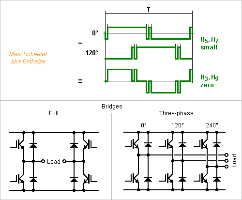
We can combine both methods to reduce more harmonics: add or subtract optimized +-1 waveforms with the proper phase shift. This combines the drawbacks, but also the advantages: for instance the number of summing resistors doubles for each suppressed harmonic, which at some point a +-1 waveforms does for cheaper. ---------- Voltage differences appear in power electronics at full bridges and three-phase bridges. If two outputs are out of phase minus a fourteenth of a period, the load between them sees no H7, so using the waveforms of Jan 13, 2018 to Jan 21, 2018 that squeeze H3 and H5, the first strong one is H9. More commonly, the outputs can lag by 120°, which suppresses H3 and H9. This is done with square waves and improves with the coming +-1 waveforms that squeeze H5 and H7, leaving H11 as the first strong one. Three square waves at 0°, 120° and 240° were common with thyristors, especially for very high power. They need an additional regulation of the supply voltage, often a buck. With Igbt, sine waves made by Pwm are more fashionable. They need less filtering, avoid cogging at motors, adjust the output amplitude, but suffer switching losses. The more elaborate +-1 waveforms I propose are intermediate. They need an additional regulation, but have small switching losses, and little filtering avoids harmonics and cogging. Maybe useful for very high power, to minimize switching losses and save on costly filters. I see an emerging use for quick electric motors: http://www.scienceforums.net/topic/73798-quick-electric-machines/ Machine tools demand a fast spindle hence a high three-phase frequency; Centrifugal pumps and compressors demand fast rotating motors too; Electric aeroplanes need a high three-phase frequency to lighten the motor, either with a small fast motor and a gear, or with a large ring motor at the fan's speed but with many poles for a light magnetic path. The high frequency (several kHz) is uneasy to obtain by Pwm as switching losses rise. But for fans, compressors, pumps... whose speed varies little, a fixed LC network filters my waveforms to a nice sine. Rfid generators at low frequencies might perhaps benefit from such waveforms too, since they must filter much their harmonics to avoid interferences, which is costly. RF transmitters maybe, for LW. ---------- The selected +-1 waveforms in this table squeeze H5 and H7 since the phased sum does the rest. 7 transitions per half-period ideally suppress H5 and H7 with T=210, more transitions bring no obvious advantage in this quest. Power electronics tends to reduce the transitions that create switching losses, and want a strong H1 voltage, while spectral purity isn't so stringent, so the table's top fits better, while the bottom is more for signal processing. One single transition more than the square wave puts the H5 voltage at 6% of the fundamental, two transitions at 0.7%. At 2kHz, 100ns accuracy on the transitions suffices easily, so a specialized oscillator isn't mandatory. 0.97 and 0.93 are fractions of the square wave's H1 voltage, and the usual coefficients like sqrt(3)/2 still apply. H1 H3 H5 H7 H9 H11 | T a b c d e =================================================== 0.97 -12 -25 -27 -19 -16 | 36 1 0.93 -15 -43 -43 -21 -14 | 180 8 11 0.90 -9 nil -64 -16 -16 | 180 5 41 42 0.93 -16 nil nil -30 -39 | 210 5 14 16 0.90 -18 nil -51 -21 -12 | 120 1 4 11 12 0.87 -8 nil -61 -21 -15 | 120 2 3 4 26 27 0.77 -10 nil -77 -7 -15 | 120 4 16 17 28 29 0.93 -15 nil -77 -23 -17 | 180 1 7 9 12 13 =================================================== Marc Schaefer, aka Enthalpy
-
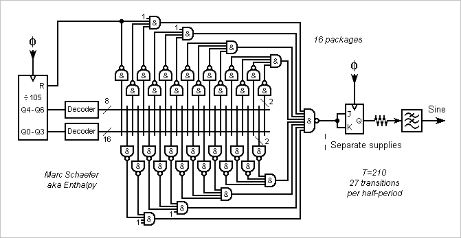
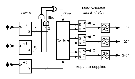
The wide Nand gates that detect the transition times from the counter's outputs are welcome with programmable logic. With packages of fixed logic instead, decoding subgroups of counter outputs allows small Nands. This diagram for T=210 and 27 transitions per half-period needs only 16 packages. The by-105 counter and transition locators in odd number make two cycles per sine period, the output JK rebuilds a complete period. The logic can be pipelined for speed; think with calm at what state decides the reset (or better preload), and then at the other transitions. -------------------- Alternately, diodes-and-resistor circuits can make the logic between a 4-to-16 decoder and an 8-to-1 multiplexer. Few logic packages and 1 diode per transition. Or use a tiny PROM easy to address by the counter. -------------------- We can also split the counter into subfactors, like T=210=6*5*7=14*15. This enables Johnson counters, which comprise D flip-flops plus few gates for N>=7, and are easier to decode and faster. For a count enable, feed the outputs of flip-flops through a multiplexer back. Traditionally, the subcounters run a different paces, and the carry outputs of faster subcounters determine the count enable inputs of slower ones. We can run them all at full speed instead: with factors relatively prime, they pass through all combinations of states in a period. Subcounters ease several phased sine outputs, at 90°, at 120° and 240°... For instance with T=210=6*5*7, common logic can locate transitions from the /5 and /7 subcounters, and these transitions serve not only twice per period, but also for the three sines, as switched by the /6 subcounter. To my incomplete understanding, Or gates can group several located transitions if their interval is no multiple of 6. Notice the T states and RS flip-flops, not T/2 and JK, to ensure the relative phases. A PROM is a strong contender for phased sine outputs. -------------------- Here's a subdiagram to make tr-tf unimportant, as proposed here on Jan 28, 2018. 4T clock ticks per sine period in this example, adding a /4 subcounter whose carry out drives the count enable of the other (sub)counter(s). Or use a PROM 4* bigger. Marc Schaefer, aka Enthalpy
-
The search programme could gain 10dB on H3, H5 and H7 with +-1 waveforms using 23, 25 and 27 transitions per half-period. Still the dumb algorithm, but the source is better written. Search27357b.zip Here's a selection of waveforms, with 21 transitions too. Among even T, 210 stands widely out. The H1 amplitude refers to a square wave while H3, H5, H7, H9 are dBc. H1 H3 H5 H7 H9 | T a b c d e f g h i j k l m ===================================================================== 0.73 -104 nil nil -23 | 210 2 7 14 16 19 20 26 28 42 43 0.34 -114 nil nil 6 | 210 3 6 7 14 22 35 36 38 43 45 46 0.59 -111 nil nil -19 | 210 5 6 10 14 16 17 19 20 29 32 44 46 0.38 -114 nil nil -8 | 210 1 2 4 6 10 19 25 34 35 39 41 43 46 ===================================================================== Marc Schaefer, aka Enthalpy
-
At last, +-1 waveforms that reduce nicely H3, H5 and H7. They take 21 transitions per half-period but only T=210. H3 H5 H7 H1 T a b c d e f g h i j ================================================================= -104 -inf -inf 0.73 210 2 7 14 16 19 20 26 28 42 43 <<<<< -110 -inf -inf 0.23 210 8 10 14 22 32 34 38 41 42 46 <<<<< ================================================================= The amplitudes of H5 and H7 are algebraic zeros almost certainly. The first waveform has its H9 some 23dB below H1, while the second has a weaker H1, about 10dB below H9. A 6 bits up-down counter takes only 11 big And gates to define all the transitions. -------------------- The harmonics that are zero to the rounding accuracy with 64-bits floats remain so with 80-bits floats, both here and for the previous waveform that suppresses H3 and H5 using 11 transitions. Marc Schaefer, aka Enthalpy
-
I had wanted T=4n for bad reasons. T=2n suffices and enables new combinations. Improving slightly over Jan 22, 2018: T=374 gives weaker H3, H5, H7 with 11 transitions than T=344, while the bigger T=856 and T=1092 still outperform both. Still the dumb software, run up to T=1040. ================================================== T a b c d e H3 H5 H7 H1 ================================================== 374 14 32 34 42 46 -73 -91 -82 0.82 ================================================== ---------- I've tried 15 transitions to minimize H3, H5, H7 with T=2n. Only up to T=434, which less stupid software would relieve. 15357.cpp ====================================================== H3 H5 H7 H1 T a b c d e f g ====================================================== -75 -73 -72 0.55 222 4 12 18 31 35 49 51 -84 -81 -96 0.81 368 11 25 30 45 46 49 51 -80 -inf -inf 0.49 420 7 18 37 47 70 77 102 -100 -73 -75 432 11 30 32 33 41 76 80 ====================================================== Found no exact solution: only -81dBc with T=368. The number of trials is too small to squeeze three harmonics by chance. Marc Schaefer, aka Enthalpy
-
Random noise is often stronger than the harmonics, yes. But in some uses, often with a narrow band, the harmonics dominate. Measuring very weak harmonics is not easy, I had already to invest some time in it. The and (or the xor) of two fast squares is, after removing the high frequencies, a triangle, full of harmonics. Making a product (call it heterodyne) of two approximate sines makes a better sine. But with squares, both third harmonics beat too and produce a third harmonic of the beat frequency.
-
Hi Frank, At the temperature of the sunheat engine, you don't have to care about ionization, catalysts nor active dissociation. The state in the chamber results from the heat whatever you do before. You should sniff a milligram of ammonia (diluted in the air!) before considering tons. You'll change your mind. If really you want an antifreeze in water, consider guanidine and pimagedine (made on Earth), which produces only gas upon decomposition. ========== Test facility: concentrated sunlight on Earth can't reproduce simultaneously the power density and the convergence angle attained in space, but both are important to test the heater. As opposed, a test setup in a lab is small, decently cheap and quickly purchased, and works in cloudy Europe too. I didn't detail it here but have clear ideas and figures about it. Easy choice.
-
Hi JC and the others! The nice toy from Intersil is a digital filter. Digital processing achieves about any performance, but when you convert to an analogue signal, the DAC spoils the spectrum. -60dBc signal purity is common, -80dBc is rare, and for the -120dBc or -140dBc I needed in some applications, there is no other means than an analogue filter, with components chosen for linearity. Fortunately, my pure sine accepted a fixed frequency then, so the analogue filter was reasonably easy. "Only" a matter of isolation and clean routing for electromagnetic compatibility. But if the frequency must vary by more than a factor of 2 or 3, you have no fixed corner frequency where you can put a filter cutoff to separate the varying fundamental from the varying harmonics. One approach, seriously difficult, is to build a (very linear) filter whose corner frequency follows the wanted fundamental frequency. The other approach, for which I propose the waveforms here, is a means to create a fundamental that is free of the lower harmonics, so that a fixed filter removing the higher harmonics suffices. ========== Pure sine from a noise: if a filter has a very narrow bandwidth, its output resembles a sine over a limited duration. If you observe it over a longer time, the amplitude and phase of the pseudo-sine fluctuate. It's Heisenberg's energy-time uncertainty, call it bandwidth-time for electrical engineers. ========== The exercise: it's a matter of power, independent of the ohmic value, and the bandwidth decides rather than the carrier frequency. Your power is 0dBm, the 300K noise is -174dBm/Hz. So if you measure over a 15kHz=42dBHz bandwidth you detect (depending on the certainty you want) harmonics of -132dBm = -132dBc, over 1Hz bandwidth -174dBc, and so on. Now, if it's an audio signal, our ears don't hear such a purity, and the loudspeakers introduce more distortion than the amplifier. I had built inductive transmitter and receiver to locate a rocket on the ground. With 1Hz bandwidth (triple heterodyne, synchronous local oscillators, and more) around 457kHz I detected -172dBm. Radioastronomers use correlation receivers that integrate over hours, and their noise temperature is more like 20K.
-
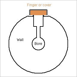
Dear musicians, scientists and everyone, here are some thoughts about the losses introduced on purpose in wind instruments. ========== To begin with, the chambers that the oboe has at its tone holes. I claim they serve to attenuate the high harmonics that are especially unpleasant on a double reed. I haven't seen up to now that thesis in books and research papers (which I haven't read all) but I suppose it is well known from oboe manufacturers. The oboe has quite a narrow bore, some 2mm at the top, and its tone holes are even narrower to soften the sound, as opposed to a flute or saxophone. Here I take 1mm wide holes where the bore has 4mm; having no oboe at hand, I can be badly off. A finger or cover could easily tap such a hole, but oboes have chambers where the tone hole is wider. I take 3mm width for the chamber, and 4mm+4mm height - unsafe guess. The closed tone hole builds a lossy Helmholtz resonator. The D=1mm L=4mm bore makes an inductor of 6.2kH and, at 4.5kHz, 3.0Mohm due to friction losses. The D=3mm L=4mm chamber makes a capacitor of 200fF and, at 4.5kHz, 15pS due to thermal losses. The finger or pad bring more losses, unaccounted here. The resonance is at 4.5kHz, nice to soften the sound. There, the Helmholtz shows 3.5MOhm to the bore. The wave impedance of the D=4mm bore is 34Mohm, so the lossy Helmholtz absorbs the unpleasant frequency. An oboe has several chambers that can cover a frequency range. A half-tone away from the resonance, the Helmholtz still shows 3.5MOhm +-j21MOhm to the bore, or 122MOhm losses in parallel. If the chambers are tuned one tone away from the other, they add the losses at mid-frequency, or 61Mohm, as compared with 34Mohm wave impedance. The set of chambers absorbs a continuous range that can span almost 2 octaves. That is, the set of chambers is perfect in this function. It's one of the missing features in the oboes with wide tone holes that Sax, Triebert and Gautrot tried to build. I suppose that the chambers serve also to tune the oboe. The inductance of the narrow holes lowers the pitch, but widening a D=1mm would be inaccurate, while shortening it by deepening the chamber is easy. A chamber as deep as the narrow part makes the lowest Helmholtz resonance, hence little sensitive to the chamber depth that adjusts the note's pitch. Marc Schaefer, aka Enthalpy
-
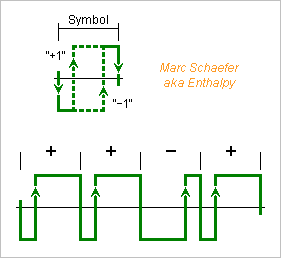
Rising and falling edges propagate with different delays to logic outputs, but here's a way to eliminate the consequences. Logic +1 and -1 states commonly decide outputs for the full duration of a symbol. An output symbol then begins with a rising or falling transition or none. Rising is done with a different delay than falling, which can be modelled by an added noise that has short peaks of duration tr-tf and amplitude +-2 at the transitions. This deterministic noise has a complicated pattern that adds unwanted harmonics to the output. I propose instead to have one rising and one falling transitions in each output symbol, and let the position of one transition, for instance the rising one on the sketch, represent the symbol's logic state. I haven't seen this before, but didn't check neither. Taking as a time reference the (here rising) edge that represents the logic +1: The position of the edge representing the logic -1 is at a time interval that does not depend on tr-tf. Only the smaller clock jitter has still an effect. The position of the (here falling) other edge is shifted by tr-tf, but this happens once per symbol independently of representing +1 or -1, so it adds a noise at the period of the symbols. Being independent of the represented sequence, it adds no unwanted harmonics. Using such symbols, we don't need any more flip-flops much faster than the analog output, which can now exceed the audio frequencies with good purity. The clock must be faster to define the positions of the (here rising) edges within a symbol, for instance 4* faster if the rising edges are at 1/4 and 3/4 of the symbol duration, but if a sequence has 180 symbols as does one described here above, the clock is only 720* faster than the analog output. This symbol representation has uses beyond the synthesis of harmonic-free sine. Notably, sigma-delta circuits can benefit from it: DAC, ADC (mind the stability) and power audio amplifiers. Marc Schaefer, aka Enthalpy
-
I've let the dumb program combine eleven transitions to minimize the harmonics 3, 5 and 7. Search11357.zip Up to T=1220, no exact solution was found, not even excellent ones, but better than a DAC: -87dBc. 1006 choices are too little to squeeze three harmonics by chance. ================================================== T a b c d e H3 H5 H7 H7 ================================================== 344 14 37 43 75 76 -71 -72 -78 0.75 980 17 58 81 152 159 -105 -80 -86 0.79 1092 41 106 122 171 173 -95 -87 -87 0.81 ================================================== Marc Schaefer, aka Enthalpy Thanks for you interest! I give in the first message estimations of the distortions introduced by the gates. I did realize and measure that one, and the observations fit the estimations. We're speaking of harmonics at -120dBc here, which isn't common. While I have already produced a spectral purity of -143dBc by an analogue filter, this was at a fixed frequency. If the fundamental were to vary by a factor-of two or more, I wouldn't like to design and build a tracking filter with such a performance.
-
One algebraic pseudo-proof of H3=H5=0 would write the cos(a*2pi/T) and others as polynoms of cos(2pi/T) and check that the sum is zero. This path is inaccessible to hand computation. Even the waveform with T=180 needs e=32 where the contribution to H5 is a polynom of degree 32*5=160 of cos(2pi/T) that has all even coefficients. Software could do this computation exactly using ratios of integer numbers. I call it pseudo-proof because humans can't check the computation. They can only prove the algorithm and hope that the program, compiler, runtime libraries , OS, hardware... make no mistake. Alone the expression of cos160(2pi/T) has coefficients like (16080) that take almost 160bits to write, so the program or library must compute on rational numbers with arbitrary precision.
-
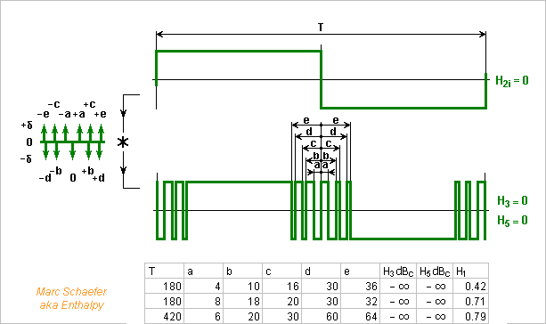
Bingo with eleven transitions per half-period: three waveforms contain no third nor fifth harmonic to the computer's precision, with periods of 180, 180 and 420 clock ticks only. Very probably algebraic solutions, if someone proves it. Up to some 1000 ticks per period, the software finds only exact multiples of these three waveforms, including at their common multiple of 1260 ticks. Search1135.zip The former diagram suggestions save more gates here. The circuit fits nicely in programmable logic. Marc Schaefer, aka Enthalpy
-
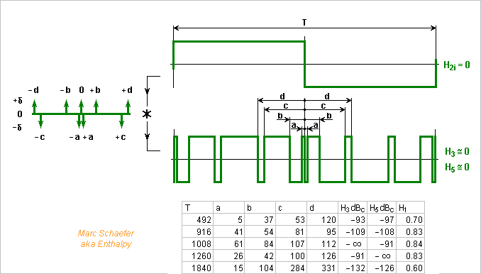
Nine transitions per half-period reduce the clock frequency further: 1840 ticks per period, that's 36MHz for 20kHz, and keep H3 and H5 at 132dB and 126dB below H1. Some solutions are exact (very probably) for one harmonic, but none is for both harmonics, up to 2500 ticks per period. Found again by software that exhausts the computer more than the programmer's imagination. Search935.zip The counter could go up for a quarter period of the output signal, down for the next quarter period, and again for the next half-period. That would use the same Nands four times per period, reducing their number. Send the adequate Nands Or'ed to the output flip-flop as previously. With an integer number of ticks per quarter-period, such a counter must stay at the extreme values for two ticks, for instance with an extra flip-flop. Other period lengths and transition positions should spare that. No diagram, sorry. Marc Schaefer, aka Enthalpy
-
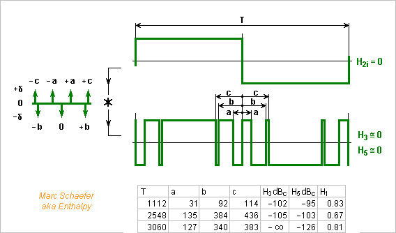
Adjusting continuously two transition positions lets suppress two harmonics, but positions approximated by a counter need a fast clock. Here, I propose to use 7 transitions and a slower clock. 7 transitions per fundamental half-period have shown no solution exact for both harmonics, but the number of positions combinations lets chance provide some good ones. This time, I let software make an exhaustive search: number of clock ticks per fundamental period, positions of the transitions. Dumb programmer but fast computer. Search735.zip 3060 ticks per output period need a 60MHz clock for 20kHz: 74AC counters and pipelined logic achieve it, an Epld is more compact. The waveform squeezes H5 to 126dB below H1, and H3 to nothing. The residual amplitude around 10-16 fits the computer's inaccuracy and chance can't decently explain it, so it must be an algebraic solution for this harmonic. This diagram is simpler. A toggle flip-flop reuses the logic for both output half-periods, increasingly useful with more transitions. The main counter has one bit less. Marc Schaefer, aka Enthalpy
-
Here are two records of oboes made of Pmma by a known luthier. Pmma is polymethyl methacrylate, like Plexiglas, Altuglas and more https://en.wikipedia.org/wiki/Poly(methyl_methacrylate) https://www.youtube.com/watch?v=NrJy8tNlBuQ music begins at 1:26, check especially the low notes at 1:55. That same musician played other instruments on the same day with the same reed, the trials are available on the same site - so only the instrument is to blame. https://www.youtube.com/watch?v=8AJnQk3ECYE music begins at 0:38. The low notes are again the worst. Two different musicians obtain the same sound, which is also how you expect a plastic to sound. It strikes even through computer loudspeakers. In short: inadequate material. Now I believe more easily that the material makes the difference between grenadilla and cocobolo oboes (Nov 07, 2017 here). And while an oboe must be more sensitive to the walls' behaviour, I believe more easily the clarinettists' comments against plastic. ========== Can the elliptic resonance explain it? Take E~2.5GPa and rho~1200kg/m3 for Pmma. The body widens to D~40mm at the low notes, and I take 5mm thickness, so (Nov 13, 2017 here) the first resonance for a cylinder would be around 3.3KHz, which is both our ear's maximum sensitivity and within strong harmonics of the oboe, like the 11th for low D. Most baroque oboes had rings at the bell, where locally thicker wood stiffened the wall. Their wood was more flexible than grenadilla. This may apply to plastics too. PC (polycarbonate) is less stiff than Pmma but it damps the resonances. Possibly a less bad material than Pmma - more factors matter. And polyketone, known for silent gears, could be worth trying. ========== Tárogatók are already made of boxwood (Buxus sempervirens), probably by tradition, and because wide grenadilla would be too expensive if available. Modern bassoons use even the flexible maple (with a thick moisture liner) instead of grenadilla or rosewood a century ago. They would be prime candidates for polyketone. I've seen no formulation loaded with short graphite fibres, but maybe plastic injection companies can do it if not the suppliers. And when long graphite fibers are wound to make axisymmetric parts, they are first impregnated by some resin: is molten polyketone feasible? Marc Schaefer, aka Enthalpy
-
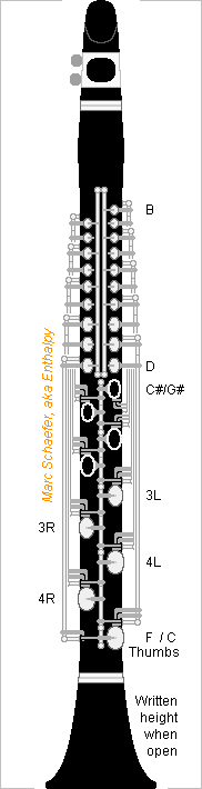
Here's a possible aspect of the clarinet with the automatic cross-fingerings proposed on Jan 07, 2018. Uncomplete, as the trill keys, register keys, and transmissions to the thumbs are not displayed, buttons for the ring fingers and pinkies neither. Most consequent holes are doubled, because a position can be opened by a closed-to-open transition of the finger holes with one mode key or by the next closed-to-open transition with the other mode key, and separate covers do that. Pairs of consequent holes that react the same way to the finger holes (but respond to different mode keys) use here long concentric shafts reaching the finger holes. A consequent cover is open at rest but often closed: When the lower of its controlling finger holes is closed, pushing directly. When the higher is open, so its rest spatula pushes down. When the proper mode key pushes on the consequent cover. As a variant, if the long shafts act indirectly on the consequent covers, only half as many shafts are necessary: five single or 2.5 concentric pairs per side. The same logical function of finger holes, carried by one shaft, can then close two consequent covers. More springs and corks in series, fewer long shafts. Alternating the hands chromatically eases the hole-open-or-next-closed operation. Both hands are but higher than the right one on a Boehm clarinet. The mode keys use four shafts, superimposed by pairs hence not all displayed on the sketch. Each mode key acts on consequent covers of both sides, and has right and left shafts for that. I don't detail the transmission from the thumbs; the buttons can optionally be split in right and left too, for simultaneous use, easing the adjustments. Usual Eb clarinets have one joint for both hands, useful here. As on some Ab clarinets, no separate barrel on this sketch: this eases a register hole there, but a reamer alone won't make the bore. As far as I understand the instrument at the Library of Congress from the picture http://memory.loc.gov/diglib/ihas/loc.music.dcmflute.1244/default.html it works differently from the system I describe. But there are strong similarities. The system for conical reed instruments would resemble much. Marc Schaefer, aka Enthalpy