Enthalpy
Senior Members
-
Joined
-
Last visited
Everything posted by Enthalpy
-
Agreed that we can analyze only durable materials. Papers in French too: http://www.lemonde.fr/archeologie/article/2016/05/25/140-000-ans-avant-homo-sapiens-neandertal-s-etait-approprie-le-monde-souterrain_4926458_1650751.html http://www.telerama.fr/monde/grotte-de-bruniquel-c-est-definitif-neandertal-n-etait-pas-la-moitie-d-un-idiot,143045.php#xtor= And in English (complementary information in them): http://www.bbc.com/news/science-environment-36381786 http://www.telegraph.co.uk/news/2016/05/26/mysterious-176000-year-old-rock-formation-discovered-in-france-c/ The paper in Nature: http://www.nature.com/nature/journal/vaop/ncurrent/full/nature18291.html In German: http://www.spektrum.de/news/erstmals-neandertaler-bauwerk-gefunden/1411633 http://www.spiegel.de/wissenschaft/mensch/tropfsteinkreise-von-bruniquel-raetsel-des-hoehlen-funds-a-1094148.html
-
Human construction 175,000 years ago in Europe, that is, from Neanderthals... http://elpais.com/elpais/2016/05/25/ciencia/1464175777_166364.html 300m away from the entrance of a cave in Bruniquel, France, a wide circle seems to be man-made of broken stalactites and stones. Which changes much knowledge: The oldest constructions known to us were 100,000 years younger They were made by Sapiens Sapiens, never by Neanderthalensis Neanderthals were not known to go deep in caves Of course and obviously, the authors tell "symbolic or ritual use" as usual. An excellent way to avoid contradiction. Well, I do take the risk of proposing a use. It was a reservoir of drinking water. Drinking water did rain from the roof, as it built stalactites - hopefully at that time too. Water is the one wealth for which I'd walk 2*300m and build an artefact. The broken stalactites and stones built a basin, together with mud presently lost to erosion. From a drop every minute you can't drink, but with a basin you can collect water from several stalactites and over more time. This source was fully reliable. Possibly available at every season, not shared with animals, not exposed to damage. Fabulous. Interpretations without human intervention suggest items fallen on the ground, possibly because of an earthquake, and pushed to a circle by a stronger stream at some time. Well, I feel it easy to check: look if the stalactites on the ground are missing from the roof at that place. Marc Schaefer, aka Enthalpy
-
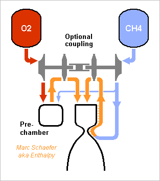
Some press papers claim an oxygen and methane engine is under development that uses a full-flow staged combustion cycle as in http://www.scienceforums.net/topic/81051-staged-combustion-rocket-engines/ and while this has been done for axygen and methane, and may perhaps work with a handful of amines http://www.scienceforums.net/topic/83156-exotic-pumping-cycles-for-rocket-engines/?p=805383 also there and following messages http://www.scienceforums.net/topic/82965-gas-generator-cycle-for-rocket-engines-variants/ I believe soots prevents methane in a fuel-rich pre-chamber. A more exotic cycle would make sense, where methane follows an expansion cycle, oxygen a staged combustion, and each pumps itself: I plan to consider coupled shafts later. Here uncoupled: Besides hydrogen, only methane fits. Ethane, propane, cyclopropane, spiropentane... stay liquid around 300K and a few 10bar. Hard-to-light fuels are excluded. Each turbine drives a pump for the same propellant. Leaks are less critical, seals are easier. Each turbopump is smaller. Not needing to pump the oxygen, the methane expansion cycle achieves a decent chamber pressure. As the methane side limits the chamber pressure, the oxygen turbine is cooler than in a usual oxygen-rich staged combustion. Two cycles must be started at the same time. The methane engine developed by SpaceX uses probably this cycle, without coupling. "Lower turbine temperature", "easier seals", "both propellants gaseous", "no soot" - and misleading "full-flow staged combustion". The hybrid cycle brings technological advantages, but how efficient is it? This depends much on arbitrary choices. 800K=527°C out of the cooling jacket, already a lot. Flowing down protects the chamber better than up. A strong engine needs several long chambers. This holds when the engine throttles to 60% thrust, so at 100%, methane exits the jacket at 515K. P/2 expansion to the turbine is best, the isentropic work to 455K is 2760J/mol. A turbine 79% efficient, pump 74%, injector 88%, and no loss elsewhere (which is unfair) leave 187bar in the chamber. Taking the usual oxygen-rich staged combustion Rd-170 as a reference, which obtains 3307m/s gas speed from Rg-1 "kerosene" at 535bar/245bar/0.8bar: Bulkier methane in a fair extrapolation of this cycle would burn at 228bar and gain 8s, Pmdeta 3s, cyclopropane 10s. The present hybrid cycle at 187bar gains 4s only. Does some decent amine mix work in a recombination prechamber? This full-flow cycle does bring performance and the same advantages. Some improvement paths: Shutting some chambers off to throttle would gain much. Or heat the methane by an exchanger at the preburner mainly. Heavy, but the main chambers are fewer and shorter, and a staged injection can regulate the methane temperature when throttling. Cyclopropane then? Couple the shafts. While the hybrid methane cycle eases the turbopump seals, it gains only 1s over Pmdeta. I'd prefer the hard-to-light fuel. Marc Schaefer, aka Enthalpy
-
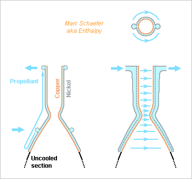
Cooling jackets waste pressure from the propellant flowing through. How much is unclear: seemingly 20% at the RL10-B2, losing 2s specific impulse, at the Vinci possibly more. The azimutal flow direction is short and broad, as opposed to the axial one, that's how I want to save propellant pressure, and several inlets and outlets in 360° would improve further. Though, the fluid layer near the surface must be replenished quickly for good heat transfer, and a slower fluid may need help for that, for instance by successive jumps that achieve a vortex pair in each channel. ---------- Ariane 6 could use an eight-chamber Vinci at the main stage, with a common set of turbopumps and actuators, and D=1.3m nozzles on a circle in the D=5.4m body. This matches Vulcain's thrust (8*171kN vs 1359kN), gains 14s (Isp=443s vs 429s) and hopefully dry mass, especially if the uncooled nozzle section is of niobium instead of SiC - and must be cheaper. The D=1.3m nozzles expand to 0.07bar hence can't start at ground level. The P120 push enough for Ariane 62 and 64, and the Vinci can start in flight. A hypothetical Ariane 60 would stop the nozzles at the cooled D=0.7m section, where the expansion to 0.34bar can be stable in the air and provides Isp = 4025m/s = 411s and 8*159kN in vacuum, and at sea level Isp = 3037m/s = 310s and 8*120kN. Inducing voluntarily a clean flow separation, for instance with the means I describe there http://saposjoint.net/Forum/viewtopic.php?f=66&t=2411 would enable the D=1.3m nozzles and improve the sea-level performance to Isp = 3270m/s = 334s and 8*129kN to lift-off 88t, enough to put 7t in Leo. Ariane 6 has four places for strap-on solids (to reuse the Ariane 4 launch pad?) but these could be liquids too http://www.scienceforums.net/topic/65217-rocket-boosters-sail-back/#entry915939 or combinations with smaller solids to fine-tune the performance. For instance the Zefiro 23 works at sea level, its stronger successor supposedly too. Marc Schaefer, aka Enthalpy
-
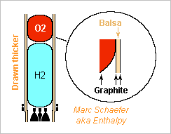
Service pack 1 for the wound graphite stage over a P120. Balsa doesn't insulate the tank heads so foam must do it, 10mm thick or less at oxygen (+16kg) and 15mm at hydrogen (+24kg). The core between the tanks must be removed once the cylinder is wound. It can be molten, taken down... but a hole is necessary. I imagine the graphite fibres can by-pass the hole(s) when they're laid down and get a local reinforcement. Ask the experts. I addressed only the azimutal contraction of the skins at cold. The axial one creates in the core a shear stress that decreases exponentially from the temperature transition over a distance (e*s*E/G)1/2 (thicknesses and moduli) and is small, about 300kPa if G=1GPa.
-
A liquid propellants launcher stage made of wound graphite composite seems light and feasible, at least on the paper. To compare, I take the same triple-chamber Vinci stage over a P120, recently estimated with metal balloon tanks in a truss. D=3.6m, H=3.9m and H=9.2m tanks make the stage but longer than a P120, so the same machine shall wind the liquid stage, but wider if needed. The balloons are wound first, as for a solid propellant but thin. They are assembled with temporary kernels, and the cylinder's inner skin is wound. ° Intertwining some strands from a ballon and the skin isn't mandatory (shear 100kPa) but seducing. It may need several strand spools with independent movements, as for waving. Balsa (or foam) core is glued on the inner skin. Foam can fill slits. The cylinder's outer skin is wound. It may require a different matrix polymerized at a milder temperature. A liner is put on the balloons' inner face. ° Perhalopolymer is known. ° Nickel, cobalt and alloys can be deposited. ° Or deposit the liner on the balloon's kernel first, before the balloon is wound. ---------- The oxygen balloon is 870µm thick (1350g/m2) to break at 550kPa, the hydrogen balloon 500µm (775g/m2) for 310kPa. Can the machine for solid stages wind that thin? At least, carbon fabric composite plies exist with 110g/m2. Buckling at 4.1MN determines the cylinder. Linear buckling theories are known (...by too few people) to fail, so I take an axial force of 0.68Ee2 from my experiments confirmed by: Nasa's SP-8007, "Buckling of thin-walled circular cylinders" hence the sandwich with quasi-isotropic (is that optimum?) skins. The graphite inner and outer skins are each 500µm thick, contributing E=170GPa as 250µm in each direction. The balsa core is 12mm thick. The sandwich is worth an e=6mm sheet of isotropic E=170GPa. The compressive stress on 2*250µm is 730MPa. The balsa core insulates the oxygen enough, and the hydrogen gets additional 10mm foam over the outer skin. The quasi-isotropic inner skin would contract freely by some 3ppm/K but the core suffices to hold it: radial 8kPa in the balsa stretch the inner skin and compress the outer skin by 60MPa azimutally. Well, fibre composites aren't that simple, but here margins are big. ---------- The insulated ballons and the H=15.4m cylinder weigh 48+140+479 = 667kg. The same functions with metal took 225+335+718 = 1278kg. Gained 611kg, wow. The dry stage weighs 1927kg with graphite, that's excellent 47kg per ton of propellants. The truss wastes diameter, wound graphite doesn't. The small compressive stress suggests that one skin and omega stiffeners, or a graphite truss, may be lighter. Though, good joints at the nodes of a graphite truss aren't obvious, while the manufacture of a wound stage is widely automatic. Being manufactured by the same plant as solids, wound graphite stages could have the historic merit to eventually convert Europe to liquid propellants. Marc Schaefer, aka Enthalpy
-
I had suggested for fixed-wing aircraft to produce electricity by a few combustion engines and use it where many propellers or fans are more efficient. Several companies and agencies work on it presently. This is even more interesting for multi-rotor helicopters like hexacopters. Much simpler than the cyclic pitch of single-rotor helicopters, they use fixed-pitch rotors whose independent speeds let pilot the craft. Electric motors are cheaper and more flexible to run the rotors. A combustion engine driving a generator is an alternative to limited batteries and to cold hydrogen. The combustion engine can be a gas turbine, with which an alternator cooperates nicely http://www.scienceforums.net/topic/73798-quick-electric-machines/#entry737931 an airliner Apu would fly a big hexacopter. It can also be a turbocharged Diesel burning kerosene, or pretty much any combustion engine. Marc Schaefer, aka Enthalpy
-
The fuel cells for the previous estimates provided 1kW/kg, but they have progressed to 2kW/kg: https://en.wikipedia.org/wiki/Toyota_Mirai which eases everything at aeroplane design. At the 255t supersonic airliner, fuel cells weigh 77t instead of 154t. Still not reasonable, but it becomes feasible. The subsonic frames were already feasible, they improve. The Atr72-42 chimera improves its freight capacity from 3.4 to 5.4t. The Piaggio 180 Avanti gains 500kg.
-
Fuels cells make progress, and quickly. Three years ago they provided 1kW/kg, now the one powering the Toyota Mirai claims 2kW/kg https://en.wikipedia.org/wiki/Toyota_Mirai which eases electric helicopters quite a bit.
-
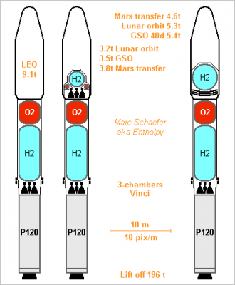
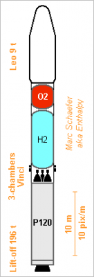
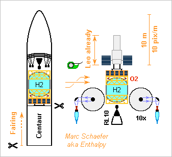
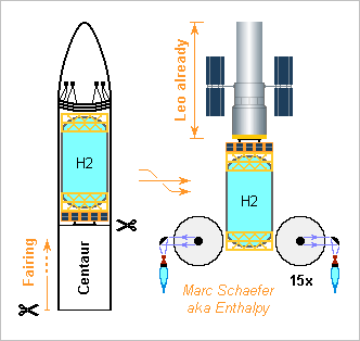
Here are second stage details and two optional upper stages for higher energy missions. The launcher matches Falcon-9's performance with limited development and looks cheap. It could replace Soyuz if this weren't lese-majesty. The P120 is designed for 3 and 2.5 stages launchers, so its thrust drops little: I take 2.5MN at shutoff from A62 needs. This imposes a too strong acceleration on a too heavy upper composite. My sailback booster is an alternative http://www.scienceforums.net/topic/65217-rocket-boosters-sail-back/ ---------- Second stage The truss transmits 4.0G when the P120 goes empty: worse than aerodynamic moments. To break at 4.1MN, it uses AA7022 tubes, Ri=34mm Ro=35.8mm, welded as 18 nodes per 0.8m stage, and weighs 718kg of which 79kg separate with the first stage. Its node diameter is 4.2m to host the 3.6m balloons; aluminium tanks welded at the truss would improve that. The surrounding shell weighs 163kg but is thrown away earlier. The balloon for 34.9t oxygen is of 250µm to 500µm (bottom) thick steel and 10mm foam hold by polymer belts. It weighs 225kg. The balloon for 9.0t hydrogen is of 280µm steel and 15mm foam that gives 500s to ignite this stage after the tower's arms open. Hold by polymer belts, it weighs 335kg. Four 750N engines control the roll while the P120 pushes, adjust the orbit and orientation after the second stage shuts off, and deorbit it. Fed from the main tanks over 10bar pumps powered by 5kg Li-poly batteries, they total 10kg. The three-chambers Vinci shall weigh 700kg with the frame, common actuators and upscaled turbopumps. The small D=1.25m nozzles bring Isp=4345m/s=443s and 171kN; thin niobium seems possible for the uncooled section to save much mass. 300kg electronic equipment, a 50kg payload adapter and 200kg undetailed items let the dry stage weigh 2459kg, or 60kg per ton of propellants. This puts 9.1t in Leo. ---------- Chemical upper stage It starts in orbit or almost and pushes 10kN only, taking 3 kicks at perigee for most missions. Multilayer insulation of the tanks spares active cooling. The truss is of welded aluminium tubes with 12 nodes per 0.8m stage. The lower part has Ri=29mm Ro=30.4mm of AA7022, these 82kg stay with the second stage. The upper part has Ri=25mm Ro=26mm of AA7020 and weighs 80kg at the third stage. The D=2.6m sphere for <=595kg hydrogen has 90µm steel (15kg), 45mm foam (48kg) that give 500s to leave the atmosphere after the tower's arms open, and 10 plies multilayer insulation (8kg) to give 50 days vacuum operation, long enough to land 1.9t on the Moon with but bigger tanks. Polymer belts (1kg) hold it to the truss. The Ro=2.0m Ri=1.2m torus for <=4739kg oxygen has 60µm steel (12kg), 10mm foam (13kg) and 3 plies Mli (3kg). Polymer belts (7kg) hold it. Maybe the oxygen would fit in the truss instead. The engine has electric pumps, better for that size and easier to develop http://www.scienceforums.net/topic/73571-rocket-engine-with-electric-pumps/ that bring 2.1kg/s of 796:100 O2:H2 to 100bar in the chambers, using 88kWe from a 114kWe 60kg fuel cell as the Toyota Mirai has - less pressure and a lighter cell would improve if available. More thrust is also possible, to target Jupiter for instance. https://en.wikipedia.org/wiki/Toyota_Mirai The fuel cell diverts 0.8% of the flux expanded separately. Four D=1m niobium nozzles expand to 20Pa for combined Isp=4842m/s=494s, wow. The engine shall weigh 30kg plus the 60kg fuel cell. 100kg electronic equipment, a 50kg payload adapter and 50kg undetailed items let the dry stage weigh 479kg, or 89kg per ton of propellants. ---------- Sunheat upper stage Thanks to Isp=12424m/s=1267s, it brings heavier payloads to farther destinations than the chemical upper stage but slower. http://www.scienceforums.net/topic/76627-solar-thermal-rocket/ Leo to Gso takes only 40 days by six engines with the inefficient spiral transfer; a year long Hohman would transfer more. The 300km Lunar orbit gets the same payload but after over a year. A transfer towards Mars needs a bigger tank than shown, and to a Martian orbit more so - but a better option would combine a chemical engine to leave Earth and capture at Mars, letting the sunheat engines change the apoapsis as described on Jul 27, 2014 in the linked thread. Gso, Lunar and Martian transfers consume hydrogen from time to time, and taking an adjusted fraction as a gas suffices to regulate the tank's pressure. Operations at a remote planet need a cryocooler during the trip. The truss is to break at 1.1MN compression to transmit lateral 2G to the payload and hydrogen. With 18 nodes per 0.7m stage, it uses welded AA7020 tubes with Ri=22mm Ro=23mm and weighs 243kg. The D=4.2m h=4.4m ellipsoid for <=2900kg hydrogen has 150µm steel (68kg), 30mm foam (84kg) that give 500s to leave the atmosphere after the tower's arms open, and 30 plies Mli (61kg) that permit 40 days wait in vacuum. Polymer belts (4kg) hold it. Six D=4.2m engines shall weigh 156kg together. 100kg electronic equipment, a 50kg payload adapter and 50kg undetailed items let the dry stage weigh 816kg. Marc Schaefer, aka Enthalpy
-
Europe has plans to develop a liquid stage put over one solid P120 booster made for Ariane 6 and Vega, nice, good. But sources suggest a new methane engine for it, which makes little sense. At identical expansion ratio, methane gains 9s Isp over Rg-1 "kerosene", yes. But so does the denser and easily produced cyclopropane. The storable safe Pmdeta gains 3s. http://www.chemicalforums.com/index.php?topic=79637.msg290422#msg290422 But a useful comparison must take the same pumping power and nozzle diameter, and then Pmdeta is as efficient as methane because its expansion is better. Cyclopropane does improve over Pmdeta, but only by 200kg despite this stage is difficult. Ariane 6 plans already hydrogen and the Vinci. Commonality tells to spread it to the middle-sized launcher, not to add a fuel and engine. Hydrogens puts 1.5x methane's payload in orbit. It needs only 3 existing Vinci chambers and short nozzles. A common turbopump can be just upscaled from the Vinci. A common actuator set is easy. Obviously cheaper than a new engine. Two US companies want methane to reuse hopefully clean engines, but hydrogen is even cleaner, and so should amines recomposition be, both in staged or gas generator cycles. http://www.scienceforums.net/topic/82965-gas-generator-cycle-for-rocket-engines-variants/ http://www.scienceforums.net/topic/81051-staged-combustion-rocket-engines/#entry785456 (with a safer amines mix). The Europeans can't overtake US companies by copying them with a decade lag. Two new engines would probably replace the Vulcain at Ariane 6, just like SpaceX will supposedly use two methane engines at a Falcon 9 first stage, but a seven-chambers Vinci does it better. Here's how the launcher can look like with the three-chambers Vinci: The design is difficult because a P120 pushes an estimated 2500kN at the end for Ariane 62, so the full liquid composite must weigh 52.5t to limit the acceleration to 4G and it must provide 6558m/s to Leo. This bad staging needs light tanks but achieves 9t in Leo, deserving a wider fairing than Soyuz ST. Details should come. Marc Schaefer, aka Enthalpy
-
Hi Dakukaruma, Graphite is generally used as a good heat conductor, not insulator. I also suspect it to dissolve in liquid iron and possibly more molten metals, making them very brittle. You could check what materials are used in a blast furnace. What metal or alloy do you plan to melt? Tin and lead are easy, aluminium is reasonably feasible, copper and its alloys are already difficult and iron much so, because of the necessary temperature.
-
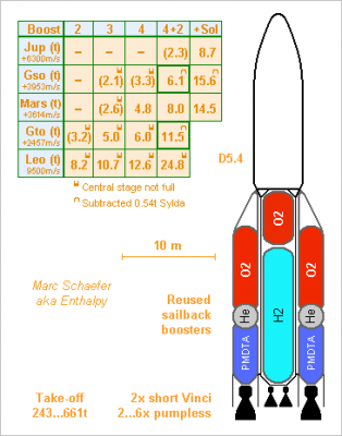
Ariane 5's main Vulcain engine is ruinously expensive old stuff, but as of 1Q2016, it shall propel the first stage of the hopefully cheaper Ariane 6. I described a simpler multichamber bleeding expander cycle engine and a launcher: http://www.scienceforums.net/topic/82346-expansion-cycke-rocket-engines/#entry798510 add side boosters to adjust the Gto capacity from 6.5t to 11t. I also describe a Vulcain equivalent that may be simpler http://www.scienceforums.net/topic/81051-staged-combustion-rocket-engines/#entry840239 and less common pumping cycles too. Several Vinci chambers could share a set of turbopumps and actuators http://www.scienceforums.net/topic/81051-staged-combustion-rocket-engines/#entry840239 where the chambers exist already and the turbopumps are just scaled up. Though, it needed to develop a new pumped engine. Here I propose an Ariane 6 equivalent, with two short Vinci but no Vulcain, and pressure-fed reused boosters instead of expended solids. ---------- The central stage carries 59.5t propellants. This is a lot for a last stage, but balloon tanks in a truss shall make it light enough. The oxygen tank (250kg) is 500µm brazed Maraging steel; a thinner top would save mass. 300µm Maraging (350kg) carry the hydrogen. 10mm foam (31kg) insulate the oxygen and 30mm (219kg) the hydrogen for 10mn before take-off. Above the foam, 5 plies (11kg) of multilayer insulation keep the oxygen cold in orbit and 20 plies (106kg) the hydrogen for 5 days. Polymer fibre belts hold the oxygen (58kg) and hydrogen (12kg) tanks in all directions to the truss. To break at 3.1MN*m, the truss has ID=46mm OD=49.4mm L=0.69l AA7022 tubes (0.49kg), thicker (13g) at the ends welded on 18 nodes (0.45kg) per turn. The 32 stages of the 19m truss weigh 1139kg. Graphite composite could gain 750kg payload. A shell protects the insulation in the air. 10mm foam, with 20mm thicker ribs at 10% of the surface, weigh 600g/m2, and aramide composite adds 100g/m2 at each face. This weighs 191kg but the tiles are thrown away after the fairing. Each short Vinci shall weigh 280kg - no data available. A 70kg aluminium truss holds them. A toroid connects the fairing, the payload, the central stage and the side boosters directly. This reduces the bending moment on the central stage. To transmit 0.5MN to or from each side of a booster, it consists or a triangular section materialized by a space truss with 12 nodes per turn and graphite composite tubes. The outer ones have estimated ID=104mm OD=113mm. The toroid weighs about 220kg, saving 0.4t over metal. With 300kg equipment and 400kg undetailed items, the dry central stage weighs 3730kg. ---------- 2, 3, 4 or 4-then-2 side boosters adapt the performance much. Each pushes two of the toroid's six points which can be shared by two boosters: this relieves the toroid when four boosters accelerate the two full ones to be ignited later. The Isp and maximum thrust are 2971m/s=303s and 2.33MN in vacuum, 2569m/s=262s and 1.95MN at sea level, expanding from 36bar to 47kPa. Throttling is easy, even at sea level, so some thrust more wouldn't hurt. At the end, the thrust has dropped by a half like the pressure in the chambers and the propellant tanks to lighten the helium tank, and the dry boosters weigh only 110kg per ton of propellants. Sailing back home for reuse is described there http://www.scienceforums.net/topic/65217-rocket-boosters-sail-back/ Fewer boosters give less speed to the central stage which isn't filled then so it accelerates well. Alternately, the Vinci could ignite before the side boosters shut off, even as soon as the vacuum permits it. Ar6VinciPairPress.zip ---------- The 3.7t well insulated central stage reaches the geosynchronous orbit directly, more efficiently and safely than hydrazine at the satellite, and more quickly than a plasma engine. That's reasonably its highest energy - Mars and our Moon are easier. Missions to far planets would benefit from an added escape stage, smaller and lighter. Electric pumps would fit best: http://www.scienceforums.net/topic/73571-rocket-engine-with-electric-pumps/ but my sunheat engine ("+sol" in the perf table) starting from Leo beats every chemical stage to reach the geosynchronous orbit, our Moon and the planets. http://www.scienceforums.net/topic/76627-solar-thermal-rocket/#entry754360 I computed with a faster spiralling transfer to Gso, and an elliptic escape without chemical kick for the planets. Marc Schaefer, aka Enthalpy
-
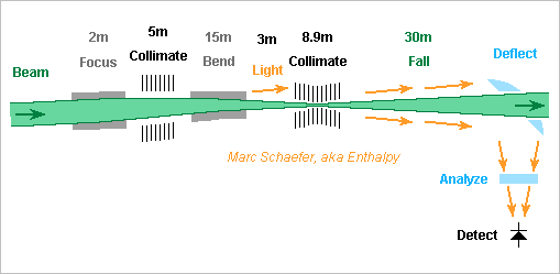
Even if stray light can be reduced below the signal (hints about the polarization filtering should come later), detecting 4.7*10-6 photons per second looks extraordinarily difficult, but here are some thoughts. With sensors that give one electron per photon, the amplifier introduces a stronger noise. I exclude them as is generally done. ---------- Focus the light The particle beam emit light over 30m path in a 2*130µrad cone, or rather 2*325µrad to catch most light. Focussing right at the end of this path, as on the drawing, would let the big depth of field blurr the image and impose a too big sensor. The concentrating lens or mirror at (excessive) 100m +-15m instead, after a first deflection, can focus to 0.1m +-16µm. From typical R=13mm, diffraction at 540nm makes an R=2.5µm spot, so R=6µm contains most power, and the depth of field adds R=0.5µm. With a difficult adjustment, the sensor's active area can be R=15µm. Maybe the optics could attenuate stray light produced upwards the particle beam's free-fall section. Especially, several out-of-axis lenses or mirrors would aims at the middle of the free-fall section and attenuate the start and the end. This has other drawbacks and I don't consider it here. The surroundings must be cold to emit no stray light, the optics probably too. Cold detectors may demand a coupling fibre not considered here. An expert would do it better and more accurately. ---------- Transition Edge Sensor (Tes) : candidate A thin small superconductor is hold just below its transition temperature, the heat of each absorbed photon creates a short-lived resistive spot. https://en.wikipedia.org/wiki/Transition_edge_sensor Measures on an optimized Tes are given there http://arxiv.org/abs/1509.02064v1 concise http://arxiv.org/abs/1502.07878v1 detailed it detects 95% of the photons and has an intrinsic dark count rate of 1*10-4/s at 80mK. The pulse rises in 200ns and drops in 4µs. Supposedly radioactivity and cosmic muons create at a rate of 1*10-2/s stronger and longer pulses that can be discriminated. For any sensor, the underground Lhc is quieter, and purer materials can be chosen. Also, our photons around 540nm versus 1064nm might help reduce the dark count rate by reducing the sensor's sensitivity: colder or less current. Ideally, the signal detection rate is 4.2*10-6/s. The active area, R=15µm versus 25µm*25µm, keeps 1.1*10-4/s dark count rate. The Tes won't discriminate the 230ps bunches nor their 2.5ns spacing period, but let's say that the 2808 bunches can come in groups longer than 200ns and spaced by more than 200ns: then the experiment can be receptive for 7µs over a 89µs storage ring turn. The dark count rate drops to 8.7*10-6/s over the active experiment time. The rest of the time serves to estimate properly the dark count rate. The signal-to-noise achieves 1*sigma after 0.5Ms = 6 days and 5*sigma after 5 months. The Lhc has already run with 3* as many bunches; this would slash the experiment time by 9. More particles per bunch act the same way. A Tes with dark count rate /10 would slash the experiment time by 10. ---------- Superconducting Nanowire Single Photon Detector (Snspd) : less good Here an absorbed photon break a Cooper pair, and the increased current density in the nanowire creates a resistive section. https://en.wikipedia.org/wiki/Superconducting_nanowire_single-photon_detector Measures on an optimized Snspd are given there http://arxiv.org/abs/1307.0893v1 this one detects 5% of the photons and has a wildly extrapolated intrinsic dark count rate of 1*10-4/s at 2.3K and 20.5µA - 540nm may help too. It resolves 230ps but doesn't resolve the energy, so radioactivity and cosmic rays must be minimized. Ideally, the signal detection rate is 2.4*10-7/s. The active area, R=15µm versus 10µm*10µm, raises the dark count rate to 7.1*10-4/s. The experiment is sensitive during 2808 bunches of 230ps, or 1/138 of a turn. This squeezes the dark count rate to 5.1*10-6/s of the active experiment time. The signal-to-noise achieves 1*sigma after 89Ms = 2.8 years active time and 5*sigma after 71 years. The bunches and particles per bunch act the same way, the dark count rate too, and the detection probability acts squared. ---------- Single Photon Avalanche Diode (Spad) : no In the "Geiger" mode, the voltage lowered below the breakdown stops the avalanche and is then set above the breakdown until noise or a converted photon triggers the avalanche - other modes would be more noisy. https://en.wikipedia.org/wiki/Single-photon_avalanche_diode Only 5% of the photons trigger http://www.perkinelmer.de/CMSResources/Images/44-3477DTS_C30902.pdf while the -20°C dark count rate is 450/s, 77K reduce it only /200 https://indico.cern.ch/event/51276/session/14/contribution/278/attachments/967044/1373321/278_collazuol.pdf silicon works badly at deep cold, other semiconductors tend to leak more. The active area can shrink from C30902SH's 0.2mm2 to R=15µm, reducing the dark count rate /283 ideally. This leaves 8*10-3/s dark count rate, a bad figure combined with the 5% detection efficiency - unless a better component exists. ---------- Photomultiplier Tube (Pmt): the challenger? https://en.wikipedia.org/wiki/Photomultiplier https://www.hamamatsu.com/resources/pdf/etd/PMT_handbook_v3aE.pdf a GaAs photocathode offers 15% quantum efficiency (handbook p33 = pdf p47) and a bold extrapolation of the fig 4-40 (pdf p84) would bring the dark count rate from 1/s @-40°C to 1*10-3/s around -100°C. The pulse can be 1.5ns wide (pdf p62). Energy discrimination is possible. Signal detection rate 7.1*10-7/s. The experiment is sensitive for 1.25ns (half cavity period) of 2808 bunches, or 1/25 of a turn, reducing the dark count rate to 3.9*10-5/s of the active experiment time. The signal-to-noise achieves 1*sigma after 77Ms = 2.4 years. BUT: I see no hard limit to really cold operation. The dark count rate must sink. It has fewer causes than in semiconductors, and the vacuum can improve too. The glass and metals can be synthesized nearly free of radioactivity. Na seals glass on Mo, no K is necessary. Some constructions resolve the 230ps bunches, reducing the experiment time /5.4. The photocathode uses to be huge: 10mm*10mm, or 100,000* our needs. The main dark current cause, the thermoionic current, must shrink with the area. Manufacture it tiny by semiconductor processes, or just deposit a material with a big electron work function (Au, Pt, Ir...) over most photocathode area but the useful D=30µm. If the smaller photocathode works, the photomultiplier tube is also a challenger for fibre optics and more. Marc Schaefer, aka Enthalpy
-
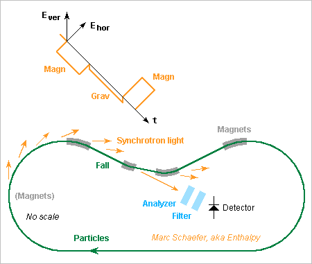
A particle beam focused at the experiment helps reduce the stray light in an adapted setup. Here 2*10µrad rms let converge from 2*150µm rms to 2*24µm rms within 30m almost as at the collision points. Focusing (2m, 180mT at r=1*sigma) adds stray light (2*10-22 J/proton) with both polarizations, but a subsequent bending magnet separates the beam from previous light. A first collimator with D~6mm L~5m removes the light beyond +-1.2mrad but diffracts a bit. A 3.1T dipole extracts the beam from previous light by 2mrad in 15m. Its accurately vertical field creates stray light (9*10-18 J/proton) but very little is vertically polarized. A second collimator removes much stray light, including in the beam, because its small openings diffract it between the many stages. The central 4.2m have 2*250µm wide square holes that spread the first lobe to +-1.2mrad. The next stage 520mm away lets -9dB through, 1+8 stages -74dB. The previous 2.7m have 2*400µm holes. First lobe +-1.5mrad, 667mm spacing. 4 stages let -36dB through. The following 2.7m gain 36dB too. The first hole get about -8dB of the bending magnet's stray light, so -154dB emerge from the collimator. To preseve the clean polarization, the collimator steps are split in pairs of successive horizontal and vertical slits. The blades (graphite?) are straight, accurately oriented and their position adjusted dynamically. I won't check the stray light created by residual gas, by rogue particles hitting the blades (put the upstream ones narrower), nor the cosmic rays and natural or induced radioactivity. Collider people know that in detail. Over 30m free fall, the particles emit (or not) a few vertically polarized photons around 600nm wavelength. Something deflects most photons (first lobe +-4mm) away from the beam (+-300µm rms): a flat mirror, a concentrating mirror, the analyzer... It must preserve the clean polarization. A separate analyzer can't stay upstream since it can't have a hole. The filter was a false hope and drops away. The analyzer removes the remaining horizontal photons created by the last bending magnet. More details should come. The detector must be very silent. More hints should come. Marc Schaefer, aka Enthalpy

-
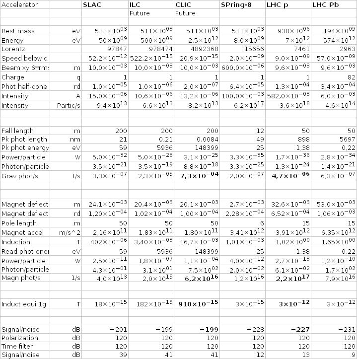
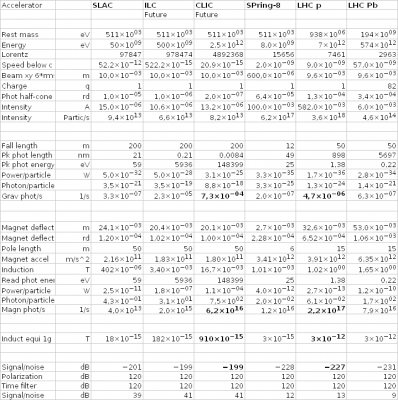
This is a setup example. Neither the scale not the shape are significant on the drawing. Especially, such racetracks are rare, and storage rings use to have a dozen of short straight sections instead. Of interest is that two magnets, as weak as possible, separate the free fall section from the rest of the noisy track. They offset the beam just enough to extract it from the upstream light. Not all upstream light can be removed because some is parallel to the beam. A linear accelerator would offer more room, added if needed, for a longer free fall section and longer surrounding magnets, weaker hence more silent. Alas, linear accelerators' beam current is small. The appended spreadsheet (for Gnumeric, Excel, or see its screenshot) compares the useful synchrotron signal with the parasitic one and tells also how small the residual induction must be. GravityMagnetRadiation.zip I lack much data, especially the available straight sections, some beam sizes too. Among present machines, the LHC (large hadron collider) gives more signal photons at a more convenient wavelength. It also accepts a stronger residual induction (difficult) because it has the biggest energy per unit charge. Winner. The future CLIC is a potential candidate, providing a stronger signal, but as X-rays. The operation of the colliders and light sources thrives to concentrate the beams at the interaction points, which the present experiment doesn't need. This may enable a stronger beam, especially with heavy ions which would radiate well. The small deflections and offsets suggest that the whole experiment fits in a but wider tube, including the shutters, filters and detectors. A supersoft magnetic tube may dampen the stray induction from the ends of the magnets; over the rest of the free fall section, an active compensation must reduce the geomagnetic field from ~40µT to ~pT. The residual electric field is easier. The signal-to-noise is scary... Winning 120dB twice is a goal. I plan to describe means that tend towards these figures. Marc Schaefer, aka Enthalpy
-
Hello dear friends! Whether a charged particle radiates when falling in a gravity field has been debated http://www.scienceforums.net/topic/80770-do-electrons-radiate-from-electostatic-acceleration/page-4#entry861035 https://www.scribd.com/doc/100745033/Dewitt-1964 Whatever the prediction by plain Relativity is, a disagreeing observation would be a precious hint towards a more general theory, possibly a unification of gravitation and electromagnetism. Here I propose elements for an experiment to check it. "Elements", because the figures I have right now aren't a complete solution - but this can only improve The radiation, if any, is badly small. A chunk of lead attracting an electron would bring no chance to observe something. My proposal instead is to (try to) observe at an accelerator the synchrotron radiation of ultrarelativistic particles falling in Earth's gravity field. ---------- Synchrotron radiation provides more light to an observer facing the quick particle's path, because it makes a shorter but much taller pulse that totals more energy. The observer sees first the part of the pulse emitted as the particle's deflection begins, but because the particle nears almost as quickly as the electromagnetic field, the part of the pulse emitted as the particle's deflection ends is seen very shortly after. This near compensation of the travel times occurs only in a narrow cone around the particle's instantaneous direction, narrower or broader than the particle's deflection depending on the conditions. At least when a magnetic field deflects the particle, a known and verified formula gives the emitted power, thanks: ---------- A particule rushing horizontally through Earth's gravity falls at 1g for the Earth-bound observer. Reasons: Its kinetic energy increases the inertia, hence increases the gravity force the particle creates and experiences. Our Sun, Galaxy, other stars and galaxies create gravity fields where the Earth, the observer and the particle fall freely. If the particle's behaviour differed from the Earth's and observer's one, we would know from local observations if we're in the gravity field of some astronomical object. This is precious to make the particle less sensitive to influences other than gravity, for instance the residual geomagnetic field. ---------- My figures show three big difficulties up to now - hopefully no worse one will appear: Radiation by the falling particle is faint, even with the synchrotron amplification. Radiation by the particle in magnetic fields is strong. Accelerators' storage rings need dipole magnets, even linear accelerators need quadrupoles. The residual magnetic field at the free fall zone must be tiny, since its radiation contribution occurs at the bad location. The existing accelerators were not designed for this experiment, that's a strong constraint. I'll expose my answers - or elements as I said, because the initial figures look discouraging . But that's usual life at accelerators, isn't it? Marc Schaefer, aka Enthalpy
-
EDRS is a new relay satellite in geosynchronous orbit that receives data by laser from Earth-observation satellites (typically on low orbit hence seeing the ground stations shortly) and relays it by radio to ground stations http://www.bbc.com/news/science-environment-35446894 I suggested here on Jan 10 and Jan 15, 2016 to transmit several beacons to separate ground stations and encode data on the polarization as well http://www.scienceforums.net/topic/76627-solar-thermal-rocket/page-3#entry900362 and this works from 36,000km distance 100 times better than from the Moon to transmit much more than EDRS' 180MB/s. Several primary sources targeting different ground stations can share one mirror. Lasers pumped directly by sunlight as I suggested here on May 24, 2014 may be more efficient http://www.scienceforums.net/topic/76627-solar-thermal-rocket/page-2#entry806581 Marc Schaefer, aka Enthalpy
-
I suggested sister crafts orbiting Uranus and Neptune: http://www.scienceforums.net/topic/76627-solar-thermal-rocket/#entry756556 whose mass were inaccurate but improved anyway by my better scenario http://www.scienceforums.net/topic/76627-solar-thermal-rocket/page-2#entry818683 leaving 2t at destination. Even at Neptune, 30.1AU=4.50Tm from the Sun, concentrators can direct the 1.51W/m2 sunlight on solar cells. Fifteen D=4.572m concentrators and 50% efficient multigap cells would produce skinny 176W electricity, but the unfoldable AstroMesh claims to be bigger http://www.northropgrumman.com/businessventures/astroaerospace/products/pages/astromesh.aspx up to D=25m for AM-1 and D=50m for AM-2, of which D=12m has flown. D=25m would provide 352W electricity and D=50m 1408W without plutonium. Their RF reflector is a mesh but I hope some metallized film would reflect sunlight. The manufacturer claims fuzzy ~0.3kg/m2 improving with size, or 150kg for D=25m. The fuzzy shape accuracy and maximum frequency include 26GHz. I wish the Astromesh would concentrate sunlight for my sunheat engine, but I suppose it's not accurate enough. Targeting solar cells is easier. Earth is close to the Sun as seen from Uranus and Neptune, so the same concentrator would double as an antenna, for instance with one secondary mirror made of mesh to redirect only the RF and some mechanical or electronics means to steer the RF or light independently. Modulating the phase and the polarization cumulates again the bandwidth, but with the wideband noise exceeding the signal from Neptune, Hadamard and Reed-Muller soft-decoding gains only as the Log of the band spreading. Marc Schaefer, aka Enthalpy
-
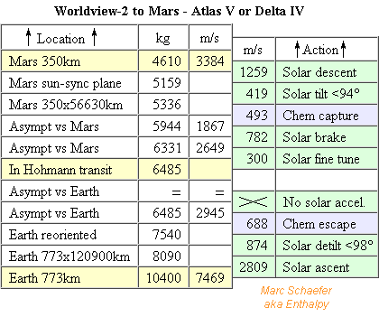
This is how to bring a decommisioned WorldView from Earth orbit to Mars orbit. We couldn't transmit a complete map at full KH-11 resolution anyway. As opposed, the lighter WorldView 2 and 3 add eight colour bands to the panchromatic one, including true colours that are all-important for public support. http://www.satimagingcorp.com/satellite-sensors/worldview-2/ http://www.satpalda.com/product/worldview-2/ https://en.wikipedia.org/wiki/WorldView-2 WorldView-2 nears its end of life, WorldView-3 leaves some years more, and GeoEye is a similar candidate, all with image quality as you experience on Google Earth. The Spot series has a worse resolution, Helios maybe. WorldView-2 moves with 7469m/s at 773km altitude. I hope to put it at sun-synchronous 350km above Mars so 3384m/s there give the same line frequency. This improves the panchromatic resolution from 0.46m to 0.21m and the multispectral one from 1.85m to 0.84m but shrinks the swathe from 16.4km to 7.4km. I checked that a D=1m F=3m paraboloid is perfect within 1nm at 773km and 2.5nm at 350km once the focal plane is adjusted - but what happens to the probable Ritchey-Chrétien is parsecs beyond my skills. ---------- The transport combines chemical propulsion at escape and capture to exploit the Oberth effect with my sunheat engines as I described here on Jul 27, 2014. This table is only from Earth to Mars hence should be clearer: An Atlas V 511 or Delta IV M+(5,2) launches the 8100kg tug to 773km 98° - or an Ariane V, an H-II, maybe a Falcon 9 if building light. The tug grasps the 2300kg empty WorldView. From 10400kg, the transport leaves 4610kg on low Martian orbit, or 2310kg for the used tug. The engine is a throttled down RL-10, possibly without nozzle extension. Since 8kN thrust would suffice, it could be a 1bar pressure-fed or 70bar electrically pumped design. 10 sunheat engines take about 10 months at Earth and at Mars. A slingshot at our Moon could spare the chemical engine. Capture at Mars by the sunheat engine remains less efficient, but the craft is simpler. ---------- To the KH-11 design, the tug adds the RL-10, a small oxygen tank (toroid on the sketch) and is smaller. Scaled like the hydrogen volume, the tank and truss would weigh 670kg, ten sunheat engines 250kg, the RL-10 300kg, leaving 1t for the equipment bay. ---------- At Mars, two engines control the attitude and orbit, four supply electricity through solar cells of varied bandgaps, four make the already described transmission. The 4/7 weaker received field loses one bit, from 6 to 5 per polarisation and phase, transmitting mean 45MB/s including the eclipses. The 0.21m 11bit complete map transmits in 4.1 years uncompressed, and the 8 colour channels with 4*4 times less resolution in 2.0 years. Marc Schaefer, aka Enthalpy
-
Reassigned concentrators help to transmit data from Martian orbit to Earth. The probe can only target one ground station. At 1.524AU (Sun-Earth distances), seven D=4.572 dishes concentrate 64kW light on solar cells of varied bandgaps. Collective 50% efficiency and 50% eclipse time by Mars leave mean 16kW supply to feed the transmitter half of the time with 7000We for each polarisation and phase. Again a 4D constellation, cubic for simplicity, with amplifiers 40% efficient at full power, transmits 5600W=+67.5dBm per polarisation and phase at the strongest symbols. Seven D=4.572*80% in-phase dishes radiate at 50GHz with +74dBi gain. At mean 1.823AU=273Gm, free-space losses are 284dB. A D=24m*80% reception dish gains +80dBi. After 3dB losses, the ground station receives -66dBm per polarisation and phase at the strongest symbols. 100MHz available band permit 40MBaud and the noise bandwidth shall be 40MHz. 30K noise temperature make -108dBm for each polarization and phase. With 6dB margin, the full-power symbols are +36.4dB stronger than the noise, so each polarization and phase swings from -66 to +66 times the noise voltage. 64 points per polarization and phase are separated by 2.10 noise voltages, so a symbol has 0.30% chances per polarization and phase of being wrongly received. A RS(4095,3935) code on 12b symbols, which have 0.60% chances of being wrong, corrects 80 positions. A few sockets of 20-core Xeon decode it using Log and Exp tables, or better one Xeon Phi. 4*6b per symbol at 40MBaud and the 3935/4095 efficient code transmit, if Mars eclipses the beam half of the time, mean 58MB/s. Of R=3390km Mars, 14PB for a D=0.2m resolution full bicolour map is transmitted in 7.5 years. Minimum data compression improves that. Or if 200MHz are available, 80MBaud of 4*5b transmit mean 96MB/s. Faster, or more colours, or better resolution. Marc Schaefer, aka Enthalpy
-
Service Pack 1 for the Keyhole-11 to the Moon... ---------- The orbit's inclination must be changed before raising the perigee: 1120m/s. Sinking the aposelene costs 605m/s. This leaves 17274kg on Lunar orbit, or 627kg less. More hydrogen also increases the tank and insulations by 111kg, so the ~3200kg equipment bay loses 738kg. Still easy. The module but fits in the Delta long 5m fairing now. Though, the equipment bay is still heavier than needed, so the module doesn't need to exploit the full capacity of the Delta V 541 (even a 531 should suffice) so the tank shrinks. If needed, the Delta operator claims it can expand the fairing. ---------- Transmissions to several Earth stations simultaneously, less oversized and hopefully less wrong now... Two 2m*5m solar panels suffice and are easier to orient. 30% efficient, eclipsed 50% of the time, they provide mean 4kW, of which 2kW feed the transmitters. That's pessimistic because when eclipsed by the Moon, the craft doesn't transmit. Here 13 small ground stations at sites with usually clear weather are separated by >2400km to cumulate the throughput of several beams - better than exaggerating a constellation modulation: 6 stations are generally visible from the Moon, sometimes 5, briefly 4. Allowing for maintenance and cyclones, the craft sends 5 beams to chosen stations. Hard disk drives shipped by boat can replace high-speed cables. Each of the craft's D=4.572m 50GHz antennas has its first zero excentered by 600km at Earth's equator, so optimized sidelobes are weak at 2400km, and the beams well separated. Aperture synthesis could replace five reflectors but is uneasy at 6mm wavelength; distinct amplifiers for the beams, possibly to distinct and interleaved antenna elements, would then preserve the amplifiers' efficiency. I take five reflectors here. Each beam modulates two polarizations and phases in a 4D (not 3) constellation, 4D-cubic for simplicity, hence equivalent to 4 independent amplitude-modulated channels. Each of the 5*4 channels gets mean 100W supply, so 40% efficiency at full power lets it radiate 80W=+49dBm for the full-power symbols. Free-space loss is 227dB at 384Mm distance and 6mm wavelength, emission by 80%*D4.572m gains 66dBi, reception by 80%*D4m gains 65dBi, 3dB are lost, so the receiver gets -51dBm for full-power symbols of each polarization and phase. 100MHz available band permit 40MBaud; smooth symbol transition put the noise bandwidth at 40MHz. 30K noise temperature make -108dBm for each polarization and phase. With 7dB margin, the full-power symbols are 50dB stronger than the noise, or 316* the voltage. 256 points per polarization and phase between -316 et +316 noise voltage are separated by 2.48 noise voltages, so a symbol has 453ppm chances per polarization and phase of being wrongly received (no Viterbi nor treillis here, provided it exists in 4D). An RS(255,243) code to correct 6 symbols has then 5e-11 chances of being wrong, or one 100Mb image in 0.4 million. 5 beams at 40MBaud of 4 bytes per symbol and a 243/255 efficient code transmit, if the Moon eclipses the craft half of the time, 0.38GB/s - almost the sensor's throughput as its swathes overlap. From our R=1737km Moon, 26PB for a D=75mm resolution full map is transmitted in 2.2 years. Marc Schaefer, aka Enthalpy
-
Thanks for your interest! So do I wonder... About the Moon, I believe to understand that only a small fraction has been imaged with 0.5m resolution by LRO because transmissions limit the amount of data, so a complete and detailed mapping would be an improvement, be it at 0.5m or 75mm. Also, as Esa proposes to Nasa to settle a base on the Moon's remote side, having good pictures first would be advantageous. Mars, sure! This was my first intent with KH-11. What stopped me: apparently Altas V Heavy doesn't start from Vandenberg, so I couldn't get enough mass on a sun-synchronous (polar) orbit, and I redirected my effort to the Moon. This explains some features oversized for the Moon, especially the datacomms. Though, the description for a lunar mission is a good start for the same at Mars. Concentrate the resources on manned Mars: yes... I consider my sunheat engine is essential for it http://www.scienceforums.net/topic/83289-manned-mars-mission/ and the sunheat engine must be proven first on an automatic mission. Transporting an existing KH11 to the Moon needs little more than developing the engine, hence is a cheap test. This delicately megalomaniac undertaking is also a convincing illustration of the engine's possibilities. 18t is about what a Saturn-V launch put on Lunar orbit.
-
The sunheat engine can bring a decommissioned Keyhole-11 from Earth orbit to Lunar orbit to make better images there. As an evolving family of spy satellites, the KH11 is little known https://en.wikipedia.org/wiki/KH-11_Kennan and much data is inferred from the Hubble Space Telescope, supposed to use the same D=2.4m primary mirror and chassis https://en.wikipedia.org/wiki/Hubble_Space_Telescope so 240nrd resolution would separate 75mm at 300km distance from the Moon too, better than presently 500mm with the Lunar Reconnaissance Orbiter https://en.wikipedia.org/wiki/Lunar_Reconnaissance_Orbiter and improved datacomms would provide us clearer images from more sites. Secrecy is a hurdle, especially since the added module provides data storage and transmission, needing to know at least KH11's downlink format - but maybe it can be reprogrammed. The optical and mechanical data is a smaller worry. On the other hand, carrying the toy away avoids to deorbit it, and the saved propellant gives an operational life extension worth 100M$: incentive. And did I read that the Nro had already offered decommissioned orbital KH? Many orbservation and spy satellites orbit the Earth: Landsat, Spot, Helios, Lacrosse... I take KH11 as an extreme example, as most others are lighter. Some are also less secret. Or Nasa can use the 2.4m mirrors given by Nro to build a new, light Lunar craft carried there from Leo by the sunheat engine; though, I'd prefer to send these to Mars, an operation I may describe later. ---------- Mass, speed and propellant An Atlas V 541 puts a 13t propulsion and data module on the same Earth orbit as the chosen KH11, say 300km x 900km x 98°. The module deploys its sunheat engines, navigates to the KH11, and grasps it delicately for 40N push. I hope no electric contact is needed: the KH11 keeps its energy supply and transmissions, the module intercepts, processes, stores and retransmits the data. I estimate the empty KH-11 weighs 13t, for no good reason, and the aggregate starts with 26t. Perigee raised to 400km costs 28m/s. This action overlaps with the beginning of the next one. Apogee raised to 326Mm, the Moon's Lagrange point's distance, costs 2931m/s. The aggregate weighs now 19955kg. Perigee raised to 326Mm and inclination changed from 98° to almost Lunar orbital plane (1022m/s forward, 89m/s polar). Cost 1026m/s leaves 18373kg. The Moon is there at that moment and catches the aggregate in a 1737+300km x 58Mm polar orbit. Aposelene sinked to 300km costs 291m/s and leaves 17901kg on the 300km x 300km Lunar polar orbit: that's 4901kg more than the KH11, for the module's structure, engines, propellant rest and data tinkering. The 15 sunheat engines push 2.7N each. This permits Hohmann transfers, making them as good as the ion engine that offers more Isp but must spiral due to its fainter thrust. As the kicks extend for long around the periapsis, I take mean 90% efficiency for the 12424m/s ejection speed at steps 1, 2 and 4. The whole transfer takes approximately 15 months. ---------- Structure The D=4.572m concentrators travel stacked horizontally. Each weighs 25kg. The 115m3 tank for 8099kg hydrogen is mean 4.4m wide and 8.5m tall. Welded AA7020 tubes machined to L=1.18m Ri=32mm Ro=33.1mm make its hexagonal truss (200kg) with 12 nodes per turn while AA7022 sheets machined to e=1.3mm except at the seams make the skin (500kg), welded at the truss for the cylindrical part and unsupported at the heads. The truss could be twice finer-grained and the skin have integral ribs. 30mm foam (180kg) let 37kW leak in. Over 15 min launch operations, the hydrogen warms by 0.6K. 50 plies of 13µm Mli (250kg) let 14W leak in, evacuated by a ~600Wm cryocooler. At each tank end, a truss of aramid or glass fibre holds to the tank. With 12 nodes per turn and 2 stages each, using L=1.18m Ri=35mm Ro=37mm tubes, they weigh 180kg together and leak <2.5W together. 1310kg insulated and supported tank and 375kg engines leave 3200kg for the equipment bay and optional hydrogen to manoeuvre in orbit. ---------- Data processing, storage and transmission Let's take 30,000 pixels wide images for KH11, with 2*12bits colours. At 75mm resolution and 1554m/s it must read 20700 lines/s, slower than at Earth: either the module averages several lines, or the KH doesn't tilt its view when observing - too little is known here. This produces 1.9GB/s, faster than can be transmitted. 5000 chips of 32GB Slc Flash store 24h worth of uncompressed sensor data. Easy to increase. On Lunar orbit, 6 concentrators are reassigned to solar cells of varied bandgaps through filters, as suggested here on Sep 20, 2014. 40% conversion provide 53kWe on dayside, of which 20kW=+73dBm transmit data. The battery for 53kW*68min weighs 470kg. 6 other concentrators work as transmission antennas. Each gains 62dBi at 30GHz - choose a frequency with muuuch available bandwidth - or 70dBi phased together. 3 own ground stations for 24h coverage have 15m collectors gaining 73dBi. After 3dB propagation losses, they receive -21dBm - the receiver can consist of a preamp, an oscillator and two diodes towards the complex baseband. If 100MHz are available and the noise temperature is 30K=-184dBm/Hz, the signal-to-noise is +83dB. 6dB margin permit 150M symbols/s of 23 bits each, for decoded 300MB/s. Phase noise isn't trivial, and the encoding shall suppress low frequencies. Can the reprogrammed KH-11 transmit so quickly? We shall modulate the polarization too, for a 3D-constellation. This was demonstrated over fibres, maybe it's already done with radio. Throughput *1.5 or 450MB/s. Still less than the sensors. 1000MHz available bandwidth would have multiplied the throughput by 8.7. Simultaneous beacons to many smaller separated ground stations would have improved too. Transmitting 450MB/s half of the time needs 4 years to map all the Moon with 75mm resolution uncompressed. Storage on Earth takes a few thousand disks. Marc Schaefer, aka Enthalpy
-
The Ehang 184, one more electric helicopter design, with secondary batteries instead of fuel cells: http://www.ehang.com/ehang184("More about product" there) http://www.wired.co.uk/news/archive/2016-01/07/ehang-184-personal-drone-car("View gallery") Opinions should expectedly vary over its general design choices. My personal dislikes are: - It knows only a fully automatic mode. As an old engineer, I claim that reliability results from humans in the loop. - It has four rotor sites instead of six and apparently no parachute. But its numbers for mass, power, energy, flight duration add up. Maybe this one breaks through, and if not, an other will