Enthalpy
Senior Members
-
Joined
-
Last visited
Everything posted by Enthalpy
-
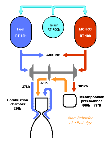
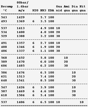
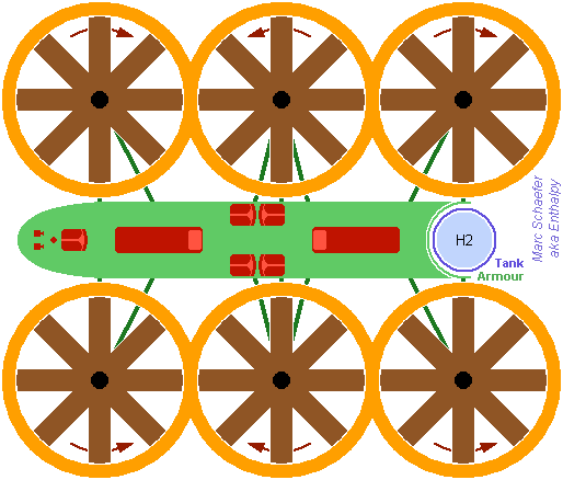
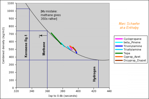
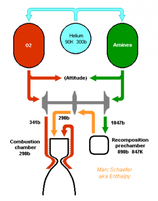
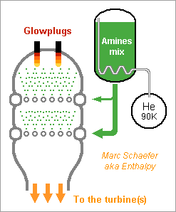
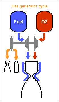
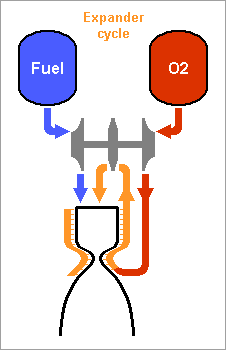
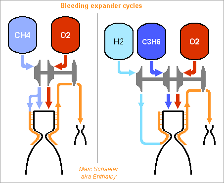
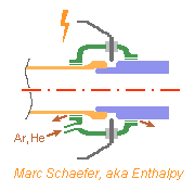
Hello you all! Many rocket engines pump liquid propellants to their combustion chamber, and varied cycles are used to power the pumps, the best known being: Gas generator http://en.wikipedia.org/wiki/Gas-generator_cycle_(rocket) Staged combustion http://en.wikipedia.org/wiki/Staged_combustion_cycle_(rocket) Expander http://en.wikipedia.org/wiki/Expander_cycle_(rocket) but here I'd like to describe uncommon cycles, which may be new and of my invention. ===================================================================== The first sketched cycle realizes the cracking (hydrogenolysis) in a pre-chamber of a hydrocarbon with hydrogen, which produces methane, some excess hydrogen, and enough heat that the following turbine powers all pumps that achieve for instance 440b in the pre-chamber and some 200b in the combustion chamber. An amine, imine, nitrile can replace the hydrocarbon: Logically, fuel density and specific impulse are between methane-oxygen and hydrogen-oxygen, thus filling the gap between kerosene and hydrogen engines: The pre-chamber and turbine run with fuel-rich hot gas, far easier than the staged combustion of hydrocarbon fuels which was oxygen-rich to avoid soot. Marc Schaefer, aka Enthalpy ===================================================================== Now, this other cycle decomposes an endothermic oxidizer in a pre-chamber to obtain hot gas for the turbine. All the oxidizer flow decomposes and continues to the main chamber. It shall be simple and reliable: No mix is required at the pre-chamber, which runs at a safe fixed temperature (but in oxidizing gas, true) Pump and turbine speed is moderate If you have some limited pressure in the tanks, opening two valves starts the engine, and the attitude control can be pressure-fed The oxidizing gas lights the fuel by its mere temperature The moderate decomposition temperature permits a sort of glow-plug igniter This cycle burns storable propellants and is more efficient than tetroxide and toxic hydrazine, like 350s with a good expansion, and its tanks are lighter. One oxidizer is Mon-33, or 33% NO dissolved in 67% N2O4. It freezes at -107°C, so if paired for instance with 2,4,6-trimethyl-tridecane (freezes at -102°C), they stay indefinitely on Mars or an asteroid or the Moon just in white tanks. Less NO lowers the vapour pressure at terrestrial temperatures, lowers the pre-chamber temperature, and loses little performance. Hydrogen peroxide H2O2 is used that way by the RD-161P engine: http://esamultimedia.esa.int/docs/EMO/LPE.pdf but to this option, I prefer a liquid oxygen staged combustion, because peroxide isn't really storable and is dangerous. http://www.gkllc.com/lit/gk-authored/AIAA-2004-4146_Field_Handling_of_hydrogen_peroxide.pdf Marc Schaefer, aka Enthalpy ===================================================================== And that other cycle recomposes in a pre-chamber a mix of amines to produce methane, nitrogen, little hydrogen, and heat: Few amine mixes don't soot. I consider Ethylenediamine dissolving 358:1000 of Guanidine. The pre-chamber, turbine and pumps work then at comfortable temperature and speed, and the hot gas is fuel-rich. Ethylenediamine NCCN or C2H8N2 is liquid between +9°C and +116°C, nearly safe, and its recomposition produces a temperature over the decomposition and the atmospheric autoignition, helping to recompose in the pre-chamber. But it needs some hydrogen supplement. Guanidine N=C(N)N or CH5N3 melts at +50°C and decomposes at +150°C. If 358:1000 dissolve in Ethylenediamine, sooting is overcome, and they hopefully lower the freezing point. Note: I've taken published -56kJ/mol heat of formation but doubt it; +56kJ/mol would soot. Methylamine NC or CH5N boils at -6°C and its recomposition is reputedly unstable, but 240:1000 in Ethylenediamine overcome sooting and should lower the freezing point. Guanidine and Methylamine dissolved both in Ethylenediamine may combine the best freezing point and vapour pressure. The sketch suggests an optional pressure-fed attitude control, but since only oxygen gives good performance here and is more difficult to store, this cycle would rather fit some launcher's lower stages. Attitude control uses to gimbal engines there, and booster pumps accepting a low input pressure save tank mass. This cycle is as good as oxygen-kerosene in a staged combustion but far simpler. Marc Schaefer, aka Enthalpy ===================================================================== For the cycle that recomposes an amine in a pre-chamber, Methylamine (MA) is corrosive and boils at -6°C, yuk; to avoid soot, Ethylenediamine (EDA) would need 100:23 of dissolved Methylamine (yuk) or 100:36 Guanidine, but the solubility and the resulting viscosity are doubtful. Alternately, Ethylenediamine could dissolve just 100:3.2 of Ammonia to suppress sooting. I've taken the heat of formation of liquid ammonia for want of the solute. Ammonia is nasty, but 3% should produce little vapour pressure - less than 100:23 Methylamine. Once Ethylenediamine contains the Ammonia bit, one can add Guanidine, Aminoguanidine or Diaminoguanidine. http://en.wikipedia.org/wiki/Aminoguanidine (beware 1720kg/m3 matches software divination) Aminoguanidine=Pimagedine was tested at 300mg/day as a drug, so it isn't very toxic. More aminated Guanidines bring heat (smoother decomposition; molybdenum turbine if needed) and performance but can't replace Ammonia - at the non-soot minimum amount in the table. In the table, added Guanidines only keep the exhaust speed of Ethylenediamine + Ammonia at best, because this comparison is at identical pressures: 700bar in the recomposition pre-chamber, 300bar for combustion in Oxygen, 0.5bar at the exhaust. But: The expansion speed from the pre-chamber improves. Power from 820m/s vs 769m/s adds 14% pressure. The fuel is denser (EDA 900kg/m3, GUA allegedly 1550kg/m3) and it needs less oxygen - both increase the pressures. 30% more pressure brings much more than the apparent 1s loss. Denser propellants make also lighter tanks. This idea fits also the fuel-rich staged combustion (if any useful) and the full-flow staged combustion, in an other thread. Marc Schaefer, aka Enthalpy


-
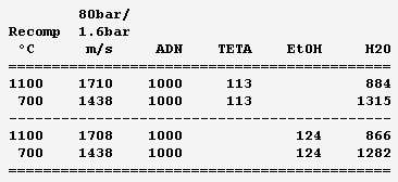
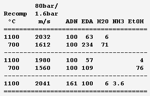
Ammonium dinitramide "ADN" (NH4)+[N(NO2)2]- is a fashionable solid oxidizer: H4O4N4, 1810kg/m3, Hf298=-148kJ/mol but dissolving adds 36kJ/mol, mp+93°C. Solubility in water is 3.57kg/kg. It's a seducing replacement to ammonium perchlorate in solid grains and a discussable replacement for hydrazine and tetroxide - I'd switch to electric propulsion or to oxygen. It looks good here as an auxiliary gas generator to rotate a turbopump. It brings H, O, N so its recomposition makes sootless gas, at 1800°C so the turbine demands dilution - hence as a liquid propellant. ---------- Here stoechio amounts of fuels are added in water. All fuels (ammonia, diaminoguanidine, EDA) gave me the same performance since the gas is mainly vapour: safety and practical consideration (melting point) can decide. These mixes make hotter gas than those based on EDA for the same performance, but they would achieve temperatures fitting (hypothetical) molybdenum turbines, and be then more efficient. They have a lower vapour pressure and are also denser. ---------- Now a fuel-richer mix produces methane and some hydrogen in addition to vapour. The expansion speed improves, but the propellant is volatile and possibly viscous, provided so much ADN dissolves. Water and ammonia prevent soot here. The previous mixes are safer. ---------- The previous injector scheme may keep useful. Other solid oxidizers are allegedly better http://www.chemicalforums.com/index.php?topic=74828.0 but I got solid data for ammonium dinitramide. Marc Schaefer, aka Enthalpy
-
True, it's not directly a turbine speed. It can be a gas speed under some circumstances, not uncommon, where the turbine is of Laval type. It does tell, through m*V2/2, how much work is extractible from this secondary flow - before the turbine introduces its losses. It also tells very much how the turbine(s) must look like. For instance, if one expands hydrogen (heated to 600°C by a little bit of oxygen) from 100bar to 5bar, it acquires 2792m/s, while a flat Inconel disk explodes around 460m/s, and an oxygen centrifugal pump needs 120m/s - by seeing such figures, a turbopump designer grasps that the turbine will be inefficient even with several stages.
-
Oops, you're right. ---------- Combustions use to be too hot for turbines. Typically over 3000K with liquid oxygen, while nickel alloys work at 700°C. A main combustion chamber can have its walls cooled by a propellant flown through a jacket, but at a rocket turbine, this would be too complicated (it's done at aeroplane engines to gain ~100K operating temperature). This is a big difficulty at rocket turbines. One answer is to detune the propellant ratio there. Easy with hydrogen, difficult with hydrocarbons: more fuel makes much soot before the temperature is bearable, more oxygen tends to burn the metals, the joints, everything. What's worse, a flame is difficult to stabilize at such a low temperature - one answer is to burn hot and dilute later - and the mixture and flame can be heterogenous, with some spots dangerously hotter, or with hotter periods over time. So a single propellant - which avoids the uncertainties of mixing - the produces naturally a mild temperature would be welcome, even more so if it doesn't soot. This is the case with hydrogen peroxide (used from the V2 to the Soyuz) and with hydrazine, but both are dangerous. The amines I suggest are caustic, but at least no brutal carcinogens, and hopefully won't detonate. ---------- The speed I indicate is for unhindered gas expansion, in this case from 80bar to 1.6bar because I found such pressures meaningful. The speed essentially indicates how much mechanical power is available in a mass unit of the produced gas, hence how much of this additional flux is required to rotate the pumps for the main propellants. In some turbine designs, the gas is completely expanded before the turbine rotor, where only the direction change provides a force, a torque and a power. There, this speed can apply directly. In many designs, the expansion occurs in part in the rotor, or is done over several stages. Then the speed indication tells a designer if the turbine speed will match easily what the turbine and pump materials survive (that's a big worry with hydrogen) and if it will fit easily what the pumped propellants need. If not, multiple stages may bridge the gap, more or less well.
-
For a gas generator that recomposes a single liquid, here are mixture attempts based on ethylenediamine (EDA). Solubilities and resulting viscosities are unknown. Solutes use to improve liquid ranges. Ammonia is dissolved, the minimum that avoids soot at 80bar; unpleasant enough, and more would reduce the performance. The optional 6% water bring pure ethylenediamine's melting point from +11°C to a -1°C eutectic; more would worsen. Dissolving loses 11cal/g heat of formation but saves ammonia and should raise the flash point from +43°C and reduce the vapour pressure, includig from ammonia. The effect on viscosity is unclear. http://www.dow.com/amines/pdfs/108-01347.pdf Guanidine loses some expansion speed put increases the density, so that more pressure can compensate, and saves ammonia. Aminoguanidine gains expansion speed and recomposition temperature, but needs more ammonia. Diaminoguanidine even more so. Less diaminoguanidine outperforms more aminoguanidine. Nitroguanidine would need much ammonia, more so than diaminoguanidine for the same performance. The expansion speed is from 80bar to 1.6bar as throttled from 120bar, a good value for graphite-fibre tanks and helium pressure feed that helps start and restart. Nickel alloys withstand the recomposition temperature, which exceeds EDA's autoignition in air (385°C) but is little for a quick reaction; injection against the gas stream may help - expect hotter regions then. Staged injection favours a stable recomposition. The helium tank is smaller if coupling it thermally with the oxygen tank. The glowplugs can be from a Diesel engine if big enough. Marc Schaefer, aka Enthalpy

-
Erratum. Guanidine isn't knowingly volatile, my mistake. Meanwhile I doubt Aminoguanidine's 1720kg/m3 at Wiki because it matches software divination. Aminoguanidine must be dense, but is there a measure?
-
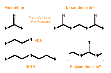
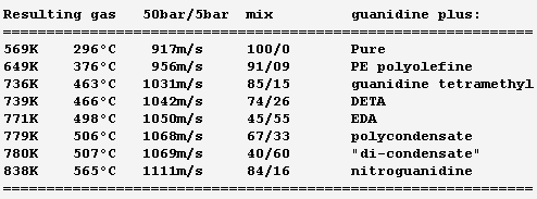
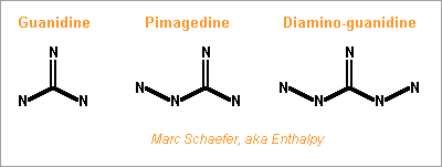
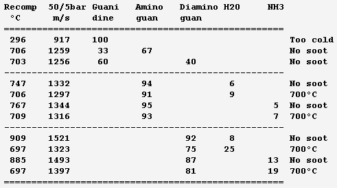
Hello everybody! The gas generator cycle is widely used on rocket engines, but some variations are still possible and desireable. For instance, the Falcon launcher burns the derived flux with much kerosene and little oxygen to limit the turbine's temperature, but the resulting soot complicates the reuse of the engine. One alternative, similar to Ariane's Viking, would add water to a tuned mix of RP-1 and oxygen, injected in two steps. 107:10:34 results in 873K=600°C; expansion from 50bar to 5bar gives 1133m/s. Good solution with one pump more. If accepting additional propellants, (yuk!) hydrazine or MMH, hydrated for 600°C, give 2004m/s and 1696m/s - not fully useable by a turbine. Methylamine (yuk as a volatile amine, not carcinogenic like hydrazines) gives 400°C and 1552m/s if its decomposition is even. Hydrogen peroxide, 84% for 600°C, gives 1099m/s but can detonate. ---------- I consider here a solid gas generator. It starts more easily, and mobile inlet vanes at the turbine can control the generator's pressure hence "burning" speed through the pressure exponent. Blowing upside makes debris less critical. One could add gelled water to smokeless powder. For instance 123:70:30 water, nitrocellulose and nitroglycerine gives 873K=600°C and 1125m/s. Expect some particles from the gel in the gas. One solid that makes moderate temperatures and no soot is guanidine: pure, it gives 917m/s and 569K=296°C - supposedly too little for a stable "flame". Guanidine may also be brittle. It's a deliquescent and caustic base that melts at +50°C. I take -56kJ/mol from a single source. Here are some additives to make a hotter and more stable "flame" and to make the block tougher - hopefully... Only experiment can tell. The mix ratio here is the soot limit. Guanidine tetramethyl, EDA (ethylene diamine) and DETA (diethylene triamine) are liquids. The hope is that they can dissolve or impregnate guanidine, evaporate partially if needed, and leave a shock-proof gummy thing that "burns" better. PE (polyolefine) would just cover guanidine grains, to bind them together and as a moisture barrier. Maybe the polyolefine is first dissolved in a small alkane that evaporates. Other polymer candidates, like varnishes, must bring little oxygen, and resist the strong base. If guanidine reacts with formaldehyde (or with ethylene glycol) like melamine does, and the water can be removed, then some "di-condensate" (isomers) shall raise guanidine's melting point and the "flame" temperature. In contrast, the cross-linked polycondensate macromolecule could be formed at the surface of guanidine grains, as a moisture barrier, flame improver, and binder or binder primer. Nitroguanidine brings heat and performance; combine with the previous ones if possible. ---------- Pumping 1t of RP-1 and oxygen to 100bar, with 74% 79% 88% efficient pumps, turbines and injectors, needs 37kg of gas at 1000m/s, which still blows at 750m/s after expanding from 5bar to 1bar. A solid gas generator adds only an envelope; at 700MPa for 50bar and 8200kg/m3, the envelope weighs some 4kg. Marc Schaefer, aka Enthalpy =========================================================================== Despite its N-N bond, Aminoguanidine (=Pimagedine) isn't toxic like Hydrazine, Mmh and Udmh are: test persons ingested 300mg/day when it was developed as a drug. http://en.wikipedia.org/wiki/Aminoguanidine 1720kg/m3 (wow!) and bp=+261°C, mp unknown. All are corrosive, caustic and deliquescent. Guanidine is worryingly volatile, but Amino and Diamino-guanidine little so. They bring more hydrogen for the same carbon, and much heat of formation, which I estimate to +60 and +177kJ/mol for the solids at 298K. Their hotter recomposition would make some soot instead of methane, worse at moderate pressure, but blends can avoid it and achieve an excellent gas speed. The blends with Guanidine are still volatile: consider coating them as previously suggested. More seducingly, tiny additions of water or ammonia suffice to avoid soot and, given their affinity for the strong polyamine, must build a solid blend. In the list, 700°C is the fuzzy limit of nickel alloys, but the molybdenum TZM alloy (which could improve the turbine of any pumping cycle) could reach 1100°C and obtain 30% more power, saving gas generator mass or improving the main chamber's pressure. http://www.plansee.com/en/Materials-Molybdenum-402.htm Water could be gelled, but I hope a better process can produce the propellant block. A carrier gas would bring vapour or ammonia between the grains of Amino- or Diamino-guanidine where they would settle and soften the surface; the block would be pressed, possibly in the final cartridge; water or ammonia would later diffuse to the depth of the grains to achieve a solid, while a light carrier gas like hydrogen or helium would exodiffuse. The cartridge can then be sealed for storage and be the pressure vessel at the rocket. This all depends on how the aminoguanidines recompose. Additives can help as usual, and fusible fibres can toughen the block. Aminoguanidines may serve in liquid blends as well, but more usefully in a staged combustion cycle, so I'll put a word there. Marc Schaefer, aka Enthalpy
-
This launcher uses hydrogen expansion cycles at both stages: a Vinci in the lighter Esc-B I describe there http://www.scienceforums.net/topic/60359-extruded-rocket-structure/page-2#entry761740 and the bleeder expander I describe there http://www.scienceforums.net/topic/82346-expansion-cycke-rocket-engines/?p=797705 The upper stage starts with 28.2t at 3000m/s below Leo. The Vinci gives it 0.65G, more than the 0.35G for Delta IV M+(5,2), so my Esc-B design can be more filled, or it can be shrinked, and the payload improves. The first stage can also nearly double with a four-chamber engine, or get side boosters. The first engine expands from 100 to 0.3bar in 2*D1,8m for 4022m/s and 2*1.60MN in vacuum, 3908m/s and 2*1.34MN at sea level. It must throttle to 50% or 40%. Jettisoned nozzle inserts, to limit the expansion to 0.8bar in the atmosphere, and larger nozzles, would gain much - or passive flow separators. The first stage has extruded tanks of AA6005A, described there http://www.scienceforums.net/topic/60359-extruded-rocket-structure/ The interstage takes t1=t2=1mm a=60° The oxygen tank, t1=2.1mm t2=1mm a=45° The hydrogen tank, t1=1.6mm t2=1mm a=45° The upper and lower heads are of 1.2mm and 1.4mm AA7022, the middle of 4mm AA6005A. With 10mm foam, the tanks weigh 6119kg or 35kg per ton of propellants. Thinner extrusions of harder alloy would improve, magnesium maybe. Add 3.5t for the engine, 0.9t for one-third of the fairing and the Esc-B shell, 2t undetailed items. Small dry masses let two stages reach Gso, Moon orbit and leave, and even a Jupiter transfer marginally. Marc Schaefer, aka Enthalpy
-
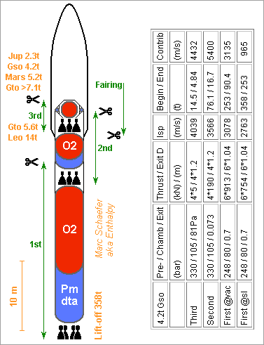
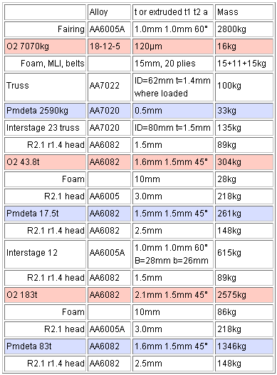
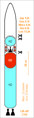
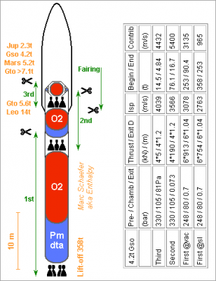
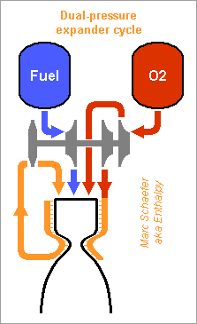
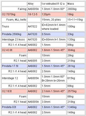
From the limited heat power, an expander cycle can pump more propellant to a lower pressure, and push stronger. I compare with Pmdeta, and 40MW per chamber to heat oxygen, as above. Because evaporation takes heat, one better keeps the same flow through the cooling jacket to obtain the same temperature, and injects the additional flow directly in the chamber. Under identical assumptions (pressure /2.7 across the turbine, pumps 74%, turbine 79%, injectors and jacket 88%, expansion to 0.7bar in vacuum, mix detuned by 5m/s for thrust), I get: 165kg/s propellants at 100bar, isp=319s, and 516kN per chamber 206kg/s at 80bar, isp=314s (-5s), 634kN (+23%) per chamber As the added flux doesn't pass the turbine, it needs only the injection pressure. Two pump stages save then power (and fit other rotation speeds better). 273kg/s at 80bar, 840kN (+63%) per chamber Because a stronger engine has a bigger chamber, the improvement is quicker than this comparison at constant cooling power. Marc Schaefer, aka Enthalpy ==================================================================== This launcher obtains 4.5MN at lift-off from a six-chambers engine that expands a fraction of the oxygen and injects the rest in the 80bar chamber directly. The other stages have four chambers and expand all oxygen to obtain 105bar in the chambers. Details on the sketch, click for full size: The fairing and the lower stages' structural tanks are vertical extrusions, as I describe there http://www.scienceforums.net/topic/60359-extruded-rocket-structure/ the 1-2 interstage breaks at 12MN and 13MN*m, the rest is stronger. The tanks weigh 17 and 19kg per ton of dense propellants, details here, click for full size: The 2-3 interstage is a welded hexagonal truss of aluminium tube, as is the structure of the third stage. The oxygen tank there is a balloon of brazed steel insulated with foam and multilayer sheet, and is hold by polymer belts. The Pmdeta tank is aluminium sheet welded to the truss. The inert masses would go to Gto in two stages, but Leo plus an optional third stage is more flexible and efficient. Storing oxygen for days and weeks, the third stage can go from 34.3° Leo to Gso (4432m/s), Mars or Jupiter transfer, Moon orbit and departure from there. Marc Schaefer, aka Enthalpy
-
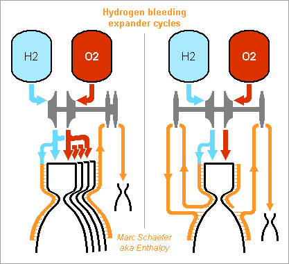
The expander cycle pumps oxygen to the chamber, and hydrogen to a higher pressure into the cooling jacket where it evaporates. Lukewarm hydrogen passes through a turbine and flows in the chamber. It gives the RL-10 and heirs good performance, simplicity and an easy start. Operation with methane was demonstrated. Though, an engine burns fewer methane moles with more oxygen moles; I propose instead to pass the oxygen through the jacket and the turbine, which enables higher pressures hence improves the performance. I compare with 400K before the turbine, 74% and 79% efficient pumps and turbines, injectors keeping 88% of the pressure - and no drop in the cooling jacket. The Vinci wastes much pressure there, but splitting the flow in shorter parallel sections should improve that. I've taken no shaft power margin neither. The nozzle expands to 7kPa. For oxygen/methane, the mass ratio is 3.64:1. Methane can expand from 402bar to 148bar in the turbine; this puts 130bar in the chamber to achieve isp=373s. Oxygen can expand from 473bar to 174bar, for 153bar in the chamber and isp=375s. Both. Evaporate at different sections of the chamber, or at different chambers, pass through distinct turbines. Separate shafts would bring nothing, but if sharing power, this achieves 540bar / 199bar / 175bar for isp=378s. Heat available from the jacket limits the thrust to upper stages. Vinci's oversized chamber achieves 180kN with hydrogen; heavier and more compact methane and oxygen bring it to half a meganewton per chamber of the same size. Cooling wih methane favours thrust, oxygen efficiency. A cryogenic propellant helps the expander cycle start; expanding oxygen permits storable fuels, which are safer than methane. Here cyclopropyl-azetidine has carefully hand-estimated Hf=+150kJ/mol and roughly 900kg/m3, but it could be diazetidine, diazaspiropentane, and methylated instead of cyclopropylate: choose for flash point. The denser fuel permits 569bar / 209bar / 184bar for isp=375s, as good as methane and safer. Since the fuel isn't heated, something like trivinylamine may be stable enough, and it achieves isp=377s. Marc Schaefer, aka Enthalpy ================================================================== The bleeding variant of the expander cycle evaporates a fraction of a propellant in the cooling jacket, extracts power in a turbine, and ejects this fraction. The bigger pressure ratio across the turbine extracts more work from the heat, so more propellants can be pumped. This cycle powers the 137kN LE-5B, but was said too weak for Ariane 6's lower stage. Though, this cycle can power a strong engine, if pumping methane rather than bulky hydrogen, as on the left diagram. Vinci's long cooling jacket provides 21MW heat for 180kN thrust, so 40MW from a roughly D0.5m*h0.5m chamber bring 43kg/s methane from liquid 112K to gaseous 300K (yes, supercritical). Expansion from 80bar to 4bar lets the 79% efficient turbine extract 10MW plus the pumping power for the bled methane, which expands from 181K to 0.7bar and about 513m/s in a secondary nozzle to push 22kN, say as a roll actuator. 74% efficient pumps bring 672kg/s of 333:100 oxygen and methane to 80bar chamber pressure plus 11bar drop across the injectors or the jacket. Expansion to 0.7bar and 3135m/s (D~1.6m) pushes 2.1MN. The bleeder and four chambers with one turbopump push 8.4MN with isp=2969m/s=303s in vacuum, and nearly 7.6MN with isp=2681m/s=273s at sea level. The turbine and pumps have compatible speeds. As strong as the RD-171, more flammable and less efficient, but easier. Burning the bled methane with extra oxygen worsens. Less thrust and more pressure improves the isp a bit. Heating the bled methane at the nozzle's bottom, as Vulcain 2 does, would also improve; better if feasible, inject the bled methane deep in the nozzle. ---------- On the right diagram, the jacket heats 8.9kg/s hydrogen from liquid 20K to gaseous 300K and 20bar, then expansion to 4bar provides 11MW to pump 675kg/s of 252:100 oxygen and here cyclopropane to 100+14bar. The bleeder nozzle expands to 1538m/s and pushes 14kN, helping four chambers to push 8.6MN with isp=3178m/s=324s in vacuum. The tanks volume ratio is 100:67:30; >20bar would save hydrogen. Again, thrust can be traded for pressure, and reheating or injecting the bled hydrogen improves. With two stages on one or two shafts, the turbine still spins at ~630m/s, too much for centrifugal pumps - but axial pumps maybe, with a single stage resembling a booster pump. Marc Schaefer, aka Enthalpy ================================================================== A bleeding expander cycle for hydrogen can be strong after all. Here, several chambers heat hydrogen by 40MW each, their common two-stages hydrogen turbine is 70% efficient, the hydrogen pump 70%, the oxygen pump 74%, the injectors or cooling jacket leave 88% of the pressure. On the left diagram, 10.7kg/s hydrogen per chamber at 100+14bar are heated from liquid 20K to 250K. Expansion from 100bar to 5bar provides 1.45MJ/kg work, of which pumping this hydrogen flux leaves 1.22MJ/kg. From 5bar and 149K (losses), the D=1.3m 0.5bar nozzle obtains 1422m/s. Pumping 620:100 oxygen:hydrogen to 100+14bar takes 43.6kJ/kg, allowing 299kg/s per chamber to accelerate to 3998m/s through the 0.5bar nozzle and push 1.20MN. The fluxes add to isp=3909m/s=399s in vacuum and 3459m/s=353s at sea level, nearing an RS-68. Obtain 4.8MN from 4 chambers, 7.3MN from 6: enough for a first stage. ---------- The right diagram re-heats hydrogen between the two turbine stages. Cooling the wall at the junction is challenging. From the same heat, it extracts some work more, and bleeds less hydrogen. This gains 2s isp and 4% thrust. ---------- The turbine speed fits a single-stage hydrogen centrifugal pump. An oxygen pump for the same shaft speed may look like an inducer, here from the M-1; symmetrize for throughput and balance. Marc Schaefer, aka Enthalpy
-
A quick electric motor-alternator, hopefully wounded with graphite fibres as I suggested, would be nice at the turbocharger of a piston engine. Rotating that fast, the motor-alternator is tiny. Coupled with a battery or supercapacitor, it permits to accelerate the turbocharger quickly when the driver requests power, and bring more air to the piston engine than the exhaust turbine permits. When braking, it regenerates energy from the turbine. A similar function exists with pressured air, but electricity is more flexible, and a battery uses to be lighter than an air tank. Splitting the turbine and compressor on two shafts, with an alternator and a distinct motor to transfer power, may bring some more flexibility. This is foreseen at Formula 1 race cars in 2014, if I interpret properly newspaper articles. Useable on any turbocharger car, and the fibre-wounded magnets reduce the mass and magnet costs over a steel sleeve, through higher azimutal speed. Marc Schaefer, aka Enthalpy
-
Separating 3He from all produced natural helium would supply a bit more than the present demand, a handful of kg a year. Though, I begin to guess a different need for 3He, in much bigger quantity... Because tokamaks such as Iter need tritium to run, and must regenerate tritium to be credible, which is a very strong obstacle: sheer feasibility and pollution, as one consumed tritium makes a single neutron needed to regenerate a tritium from a 6Li, so dirty neutron multipliers must offset the losses. I tell it for years, maybe tokamak proponents get slowly forced to look into the problem. One other way would let 7Li absorb the 14MeV neutron produced by the D-T fusion. 7Li splits into 4He and T, and releases a neutron - but with energy too low to react with 6Li nor 7Li. This secondary neutron could react with 3He to make a second T. Well thought guys, but this needs 3He in big amounts, not available from terrestrial helium deposits, and of course not obtained from T decay. This can be a reason for the query at 3He artificial production. It can also be the reason why some people and agencies consider mining 3He "for nuclear fusion" where it is less scarce: on the Moon or from gas giant planets. It's not for D-3He fusion, which is hugely more difficult than the already remote D-T fusion: it's for regeneration of tritium in D-T reactors. Well, sorry folks, but isolation from normal terrestrial helium just makes a few kg a year. And despite being a space visionary, I don't really imagine affordable Selene mines. But for a few millions instead of many billions, we would have cheap electricity storage that enables wind and Solar energy on the big scale.
-
The terrestrial proportion of 1.37ppm means: process 1,000 tons to get 1.37kg... So one better puts the separation plant at the helium well directly. Liquefying helium in big amounts isn't easy nor cheap. An alternative would be a molecular pump or a gaseous diffusion plant. Better, do both simultaneously: have a many-stage pump (for instance as an axial turbomolecular pump) and put a gaseous diffusion shunt around each stage, if natural leakage doesn't suffice. Each stage is more efficient at 4He while each shunt lets 3He leak better. Because the masses differ significantly, each step has an interesting yield. This can work at room temperature, with the speed attained by an optimized metallic axial pump. Cold improves. Natural helium would be introduced near the "depleted" (purer 4He) exit, so most flow absorbs little pumping power. Enriched 3He would exit at the pump's extreme inlet, after many steps that most helium does not pass. Many other methods must work. Gas chromatography can use many (many) short fibres in parallel, I suppose with oscillating pressure at the natural helium side so that 4He has no time to diffuse to the end of the fibres. I wanted to use a superconducting leaking ceramic to repel 3He as is done with O2, or a ferromagnet to alter the diffusion of 3He versus 4He, but since a nucleon is a weaker magnet than an electron, the effect is tiny at room temperature - much smaller than the contrast in diffusion speed. 3He seems 10 times better than Li to produce 3H from a neutron flux, that is at a nuclear reactor. That can explain the query for 3He.
-
Leaving Encelade's orbit, the probe keeps six engines and discards six to weigh 1045kg and join Pallene (212Mm at 13375m/s in 1.15 days). The 752m/s spiral transfer takes 52 days and leaves 983kg. Search for unknown moons on the path - the spiral transfer eases it. The probe has probably optical and radar imagers to inspect the known moons; a lidar may also help discover new ones. Occasionally, a concentrator for an engine, for electricity production or for radio transmissions can pump a properly doped Yag with 200W Sunlight. The R=2.5km Pallene costs nothing to approach and leave, but is too big to land. ---------- 983kg leave Pallene for Methone (194Mm at 13982m/s in 1.01 days). The 607m/s spiral transfer takes 39 days and leaves 936kg. Methone has R~1.6km so I'd rather land elsewhere. But near passes permit to fire bullets (hydrogen cannon?) to help analyze the surface, and maybe evaporate some material with the pulsed Yag. ---------- 936kg leave Methone for Mimas' orbit (185Mm at 14301m/s in 0.942 days). No trojans are reported, so it's time to check the places. The 319m/s spiral transfer takes 20 days and leaves 912kg at the first Trojan place. 60° in 60 days cost 2*12.5m/s or 2kg. Mimas' (R=198km) influence extends only 520km against Saturn, so the probe can't properly orbit the moon; I consider again a slightly tilted elliptic Saturn orbit that circles Mimas. For that, I budget 50m/s or 4kg at arrival, and as much at departure. One more hop to visit the other Trojan place, and the probe weighs 900kg. ---------- The 746m/s spiral transfer to Aegaeon (168Mm at 15047m/s in 0.808 days) needs 44 days and leave 847kg. Detect small moons and rocks meanwhile, since a ring begins there, and land to analyze them. With R~250m, ~20µm/s2 gravity (1/10th the probe's thrust) and 0.1m/s escape speed (spring), approaching Aegeon and landing costs no propellant. 200W concentrated Sunlight can evaporate snow at some distance for analysis, including without landing, but the hotter Yag is better; Sunlight may be good for an oven. Hydrogen at engine exhaust has also enough enthalpy per mole, as kinetic energy, to evaporate many materials at a moon from a limited distance; replacing temporarily hydrogen with, say, rubidium or xenon, enhances sputtering at the target, and special chamber and nozzle can keep the jet more concentrated. Three engines are kept and three discarded to weigh 772kg. The big hydrogen tank should already have been discarded, keeping a small one, but I've forgotten it. ---------- The 1411m/s spiral transfer to the main A ring (140Mm at 16458m/s) needs 138 days and leaves 689kg. As usual, detect small moons and rocks meanwhile, and land to analyze them. Venus and Earth flybys, plus smarter transfers and captures at Saturn's moons, would leave much more probe mass. The Solar thermal engine enables the described dumb scenario, but smart methods developed for chemical and ion engines apply here. At the ring, capture the smaller rocks and land on the bigger to analyze them. Continue to dive as long as hydrogen suffices. ---------- Saturn's main rings can be a separate mission. The probe passes nearer to Saturn to save capture propellant, brakes at Titan and changes the orbit inclination there for flexible launch opportunities; orbiting no moon save further propellant. Ejecting vapour instead of hydrogen, the probe finds propellant in the rings and can navigate everywhere without limit. Marc Schaefer, aka Enthalpy
-
Hohmann from Iapetus to Hyperion (orbit R=1501Mm at 5027m/s in 21.3 days) would take years, so the transfer shall push continuously. The probe brakes by 1763m/s and loses the orbit inclination of 8.31° or 601m/s as a mean. For this, the engines push up or down by 41.5° for 2*90° in each turn around Saturn, and flat for 2*90°. The perfectible de-tilting costs 253m/s, bringing the spiral transfer to 2016m/s. Beginning the push in elliptic orbit around Iapetus gives free 8m/s. Hyperion's influence reaches 2.2Mm against Saturn. The target orbit is polar 0.5Mm * 1.1Mm covered in 2.6 days, with periapsis in Hyperion's orbital plane at the daylight side. Capture computed from 50m/s above Hyperion's gravity passes with 34m/s at 0.60Mm from the moon's center, and reaches the final orbit in a single 2.0+0.4 days brake consuming 34+6m/s: 10m/s are for free. HyperionWeakBrake.zip From 3116kg in Iapetus orbit, the 2016-8-10m/s transfer puts 2653kg in Hyperion orbit in 129 days. ---------- Around the following moons, orbits computed without Saturn's influence have a period similar to the moon's orbit around the planet, and their apoapsis exceed the moon's reach against Saturn's gravity gradient, so my capture costs are inaccurate. To obtain an estimate nevertheless, which should be pessimistic, I separate the transfer between the moons' orbits from the capture by the moon, computed with the weak thrust, from zero speed above the moon's gravity, and neglecting Saturn. This would nearly be the case if the major axis were polar; though undesireable for the exploration, it protects the apoapsis from Saturn's tides. It is my hope that specialists find better scenarios. Maybe the probe can enter the Moon's well near the outer Lagrange point being temporarily the apoapsis; the first orbit around the moon would then have its apoapsis perpendicular to Saturn hence protected, giving time to lower it enough. A polar orbit with periapsis in sunlight over the moon's equator should be possible. ---------- From Hyperion to Titan (orbit 1222Mm at 5571m/s in 16 days), the spiral transfer takes 544m/s in 31 days, as Hohmann saves nothing for near orbits. But gravity assists at Titan? While Hyperion offers 10m/s, capture at Titan (3.1Mm * 25Mm) by weak thrust is counted as 298m/s. From 2653kg in Hyperion orbit, the 544-10+298m/s transfer puts 2481kg in Titan orbit in some 100 days. ---------- 2421kg leave Titan after 298m/s expenses. Big jump from Titan to Rhea (orbit 527Mm at 8483m/s in 4.5 days). Six engines are discarded to save 150kg; the 12 remaining push 0.35N and eject 3.4kg/day. The spiral transfer begins with 2271kg, costs 2912m/s and 198 days, ends with 1796kg. Hohmann would save 120m/s but is too long. Slingshots at Titan, maybe Rhea? Capture (1.6Mm * 11.9Mm in 3.3 days) is to cost 107m/s and puts 1780kg in Rhea orbit. ---------- 1764kg leave Rhea for Dione's orbit (377Mm at 10030m/s in 2.7 days), but of course the probe visits Dione's trojans: Helene before and Polydeuces after - same orbit, just separated by 60° from Dione. The 1547m/s spiral transfer takes 86 days and leaves 1557kg. Helene's (R~18km) Lagrange points are 71km away, not bad for observation if the instruments see that near. Or a minimally elliptic and tilted Saturn orbit might make a single-turn helix around Helene's orbit. Negligible fuel expense. Covering the 60° to Dione in 60 days costs 2*25m/s (would be more at Titan's orbit). Capture at Dione (1.1Mm * 7.3Mm in 2.3 days) costs 86m/s and puts 1540kg in Dione orbit. Leaving Dione and joining Polydeuces puts 1523kg there. The R~1.3km object can be sniffed from all directions at negligible cost. Its mass and density are still unknown; to my taste, estimated 200µm/s2 gravity and 0.7m/s escape speed are slightly too much to land there and analyse probes, but unknown smaller moons may float near Helene and Polydeuces. ---------- 1523kg leave Polydeuces for Tethys' orbit (295Mm at 11339m/s in 1.9 days), and the probe visits also Telesto and Calypso, Tethys' trojans. The 1309m/s spiral transfer takes 63 days and leaves 1371kg. The Lagrange points are ~38km from the trojans, no fuel expended there. 60° in 60 days cost 2*20m/s. Capture at Tethys (1.1Mm * 4.8Mm in 1.8 day) costs 77m/s and puts 1357kg in Tethys orbit. The probe weighs 1343kg at Calypso. ---------- 1343kg leave Calypso for Encelade's orbit (238Mm at 12623m/s in 1.4 days). No trojans are reported, so it's time to check the places. The 1284m/s spiral transfer takes 55 days and leaves 1211kg. Observe new moons there - maybe. 60° in 60 days cost 2*16m/s or 3kg to join Encelade. Encelade's Lagrange point is only 950km from its center, and the surface 252km... So the probe should not orbit Encelade, but rather follow a minimally elliptic and tilted Saturn orbit that makes a single-turn helix around Encelade's orbit. I budget 50m/s or 5kg to stabilize around Encelade, putting 1203kg there. I would not separate a lander nor diver there. This is worth an own mission. But a penetrator maybe. And spend all due time there, for sure. The probe weighs 1195kg at the other Trojan place. Find new moons maybe, possibly land on them to analyse probes. A spring lets take off. ---------- More to come. Marc Schaefer, aka Enthalpy
-
The Solar thermal rocket enables an extensive mission around Saturn. This first part describes up to the capture by a first moon. http://en.wikipedia.org/wiki/Saturn http://en.wikipedia.org/wiki/Moons_of_Saturn http://solarsystem.nasa.gov/planets/profile.cfm?Object=Saturn A Delta IV Heavy shall place 8808kg at 3162m/s (10km2/s2) above Earth's gravity. The eighteen 4.57m Solar engines add 7176m/s, leaving 4944kg heading to Saturn in 5+ years. Acceleration can take more than 12 days, so lighter engines are better, with diaphragms or a small secondary mirror to limit the power at one Sun-Earth distance. At Saturn's 9.582UA, each engine pushes 29mN and uses 0.2kg/day hydrogen. The necessary inclination of the capture orbit at Saturn already constraints the launch window, so no gravitational assistance is taken from Jupiter, but smarter people could use Earth and possibly Venus to save on the launcher or extend the probe; both are welcome for this high-energy mission. Outer moons have too inclined orbits, so the first target is the puzzling two-tone Iapetus. http://en.wikipedia.org/wiki/Iapetus_(moon) http://solarsystem.nasa.gov/planets/profile.cfm?Object=Sat_Iapetus&Display=Facts&System=Metric Preferring Nasa over Wiki, the orbit has 3561Mm radius and 8.313° inclination versus Saturn's equator; lower moons are equatorial. The probe arrives with 5760m/s above Saturn's gravity and brakes by 4596m/s (502 days) before a 4195m/s pass at 3813Mm from Saturn's center. 276m/s more braking (30 days) reach a capture orbit of 14490Mm*3561Mm covered in 320 days - make science meanwhile. Two peri-Saturn kicks totalling 872m/s (95 days) achieve the circular 3561Mm orbit covered in 79.3 days. Well, at least if believing my spreadsheet: SaturnWeakBrake.zip Gravitational assistance by Iapetus (escape 573m/s) or an other moon might help. The probe reaches a polar Iapetus orbit to study it, with periapsis 1.2Mm from Iapetus' center (the moon has 735km radius) and apoapsis 15Mm in Iapetus' orbital plane (Iapetus' influence reaches 36Mm against Saturn). Computed from 200m/s above Iapetus' gravity, the manoeuvre passes with 342m/s at 1.92Mm from the moon's center, and reaches the final orbit in a single 169+23m/s (11.9+1.6 days) brake consuming 192m/s. IapetusWeakBrake.zip Smarter people might enter the moon's gravity where Saturn's one makes it easier - if any feasible. The described capture by Saturn then the moon consumes 5744-8=5736m/s, leaving 3116kg orbiting Iapetus. Marc Schaefer, aka Enthalpy
-
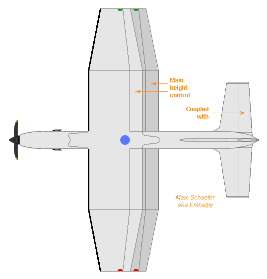
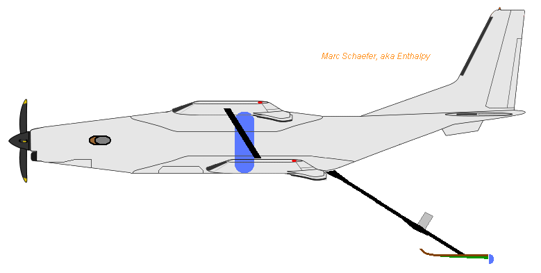
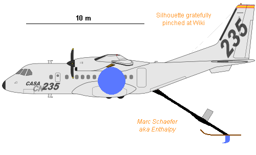
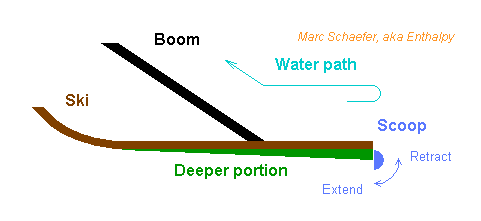
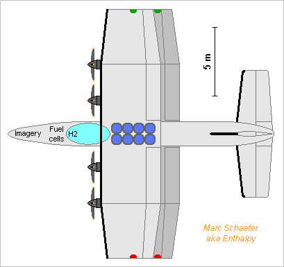
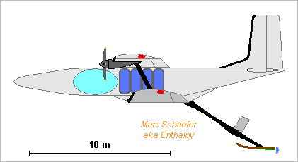
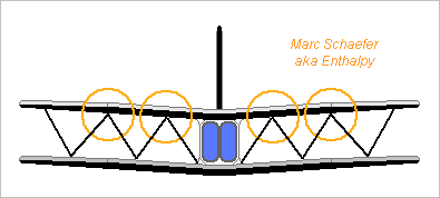
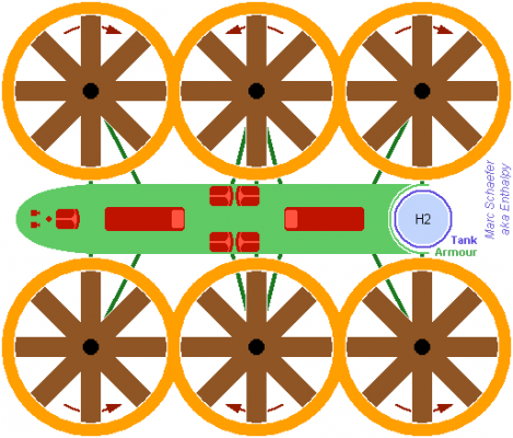
Did you play with matchsticks once again? Here comes the fire brigade, with tools of adequate size. Many aeroplanes, especially military cargo planes, have desirable performance as a water bomber: sturdy, good capacity, good climb rate, reasonable flight speed... The Bombardier 415 adds the precious ability to refill its tanks by scooping water from sea or a lake: http://en.wikipedia.org/wiki/CL-415 and I should like to explain how more usual airframes can obtain this ability. The plane flies a few metres above water and lowers a boom that scoops water to the tank(s). The boom is articulated at the airframe. Downlift comes primarily from the steering winglets. Its design is inspired by a refueling boom. A lightweight ski(s) follows the water's height. The winglet-ski combination shall alleviate shocks at the airframe by the waves. Elasticity can be built in between the winglets and the ski. Design anyway this place as the weakest mechanically. The opening of the scoop can be lower than the ski. The scoop - or its opening - is smaller than depicted. Its drag is smaller than the touchdown of a waterboat. Two-axis articulation of the boom may be better when the wind doesn't align with a small lake. Alternately, the lower tip of the boom can be well profiled to plunge deeper into the water without a ski. This may be better at rough sea. The spherical tank is to give a visual impression of the volume that the aeroplane used in the illustration can lift. Putting it (or them) outside the fuselage, like before the wheels, over the wheels or under the wing is probably better, as flushing it quickly is very important, but shouldn't destabilize the plane. Water flowing in quickly is dangerous. It needs jet breakers at the tank, and protections for the personnel. I'd let it spill over when the tank is full and provide it a wide way out of the airframe. Yes, you can take a bigger aeroplane, of course. Maybe a C-130 Hercules. But to use smaller lakes, preferably a not too fast aeroplane. Or design one purposely. A remote control would be nice as well. Marc Schaefer, aka Enthalpy ==================================================================== Only the Canadair-Bombardier CL-215 (and CL-415 with turboprop) were built purposely. Scooping procedure is summarized by pilots: http://bernard.dumas.perso.infonie.fr/Ecopage.htm http://pelican.46.free.fr/Caracteristiques/body_caracteristiques.html Splashdown at 75kts, give power once arrived at 60kts, then open the scoops to take 500kg/s water. End scooping, accelerate up to take-off at 78kts, accelerate further to 96kts then climb. Scooping takes much propulsive force, but less so in a seaplane moving slower than its stalling speed. The CL-215 flies rather slowly, as a further design advantage, enjoying a big propulsive force. In contrast, the Casa CN-235 flies faster, and would scoop in flight, hence above its stalling speed, or around 50m/s (100kts). Many cargo planes are a bit less favourable: faster, and their flatter ascent angle meaning less available propulsion force. Commuter airliners fit even less because they're faster and not as sturdy. As a seaplane, the CL-215 touches down and takes off parallel to the swell, not against the wind direction. A cargo plane must scoop parallel to the swell also. Then, at 50m/s and 10% from parallel direction, with 3m swell period (at the Mediterranean), the advantageous ski oscillates with 0.6s period and can be kept. I estimate the Casa CN-235 has over 10kN excess propulsive force available, from its 9.0m/s climb rate and 10.1t empty mass. This allows only to scoop 200kg/s at 50m/s, needing 30s and 1.5km to load 6000kg, instead of 0.3km. Irrelevant at sea, but a drawback on a lake - the penalty for a mass-produced aeroplane. Forces at the boom and the airframe are nearly simple... I take a slope of 1:2 for the boom. 200kg/s water turning from -50m/s to +50m/s create 20kN drag and 5kN down at the rear of the boom. The airframe pulls the articulated front end of the boom with zero N*m, (nearly) 20kN forward and 10kN up, but water impinging at the tank pulls the airframe 10kN forward and 5kN up. As a sum, the airframe feels 10kN drag and 5kN down. The rear end of the boom is pulled up (by the plane minus the water) with 5kN, to be compensated by >3m2 airfoil. At least one nice aspect: if the boom articulates at the right height (suppress the door), the airframe won't feel a pitch moment. Airborne scooping procedure could then be: stabilize at 50m/s and 5m, lower the boom, press the ski down with the airfoil, give power, then open the scoop. The airframe feels immediately 5kN (0.5t) down force, which would lower it by 0.5m after 1.4s, but is to be compensated. Water flowing in makes the plane heavier by 0.2t/s, to be compensated. Then close the scoop, raise the boom, accelerate and climb away, you guessed. The operation pulls toward water an airframe not designed for sea and this is more risky than with the CL-215. On the other hand, the cargo plane doesn't have to splash down, a risky operation avoided. I want that the pilot has a fast (typically pyrotechnic) emergency button to sever the boom from the airframe, in addition to the fast release of water. When scooping (and when dropping water as well) it would be better to control the plane by its landing flaps instead of its elevator. Build faster actuators there if needed. A pair of rods between the wheel fastenings, the water tank(s) and a point about 1/3 out at the wing would improve strength. Keeping the cabin pressure constant, even near sea level, would be nice to the crew. And improve all protections against corrosion... Marc Schaefer, aka Enthalpy ==================================================================== For safe operation, the ski should drag very little when not scooping. This must prohibit a scoop built deep below the ski, changed my mind. The ski may have a portion of its width reaching slowly deeper, where the scoop gets steadily water, as the best possible design. I like the latest design of the retractable scoop at Canadair's CL-415. It's a sector of a cylinder that plunges into water by rotating around its horizontal axis. Fits the ski nicely. The plane will not scoop into the wind but parallel to the swell, flying hence sideways, so the boom must move on two axis. I'd place the emergency button that severs the ski or the boom from the airframe just like the trigger button on a combat plane: at the yoke, with a latch. ==================================================================== The current fleet of water bombers is ageing: the original CL-215 was designed five decades ago, and existing planes show fatigue, the Canadair as well as modified airframes. Several airplane manufacturers think at a follower (including ultralight aircrafts, which may explain why I saw so many fly over as I was thinking at the design), and I just have to add my own frenzy to the existing mess. Among the older CL-215, Spain has lost 7 from 30 acquired, France 4 from 16. Among the CL-415, 7 have been lost from 60 built. Breaks in flight seem to be the main cause of accident, due to low flight over difficult terrain, and turbulence by wind and fire. Unspecialized airplanes use to be less solid; the C130 Hercules as a water bomber has been abandoned in Europe after two of them broke. So I consider a specialized design should have such qualities: It must be controlled remotely. The pilot stays on the ground, possibly aided by a scooper-dropper shared among several planes. The airframe must be solid and resilient against stalling. It should better be slow and drop its water well above the stalling speed. Climb rate is important, finesse far less. Carrying capability doesn't need room, as water is dense. And this is how I imagine the design: A biplane. Out-fashioned, but still naturally solid with cross struts. With more area, it lifts more weight at lower speed. The landing flaps control the pitch (though the elevator must be controllable). The water tank(s) can act as an emergency water rocket to lift the plane. A single turboprop. But I'd add a parachute, as some ultralight planes have, to land the whole airframe not too hard. Of course, scoop in flight as described above, without needing a sea plane. Though experience shall tell if it's better. The landing flaps, with fast actuators, act more rapidly on the flight than the elevator does. This is useful near the water, the terrain, or if stalling. Accordingly, the elevator is at the rear. With its wings more closely stacked than usual, and especially if the upper one is a bit before the lower, a biplane keeps more lift when stalling. When using an added tank of emergency gas to put the main tanks at 30b, flushing 10t of water lifts (and pushes forward if desired) a 10+10t aeroplane during 4s, enough to recover from stalling. Use many small nozzles. The parachute is fastened to many parts of the aeroplane, in case the frame breaks. It's probably better to let the plane decide alone if using stall recovery processes or the parachute, since the pilot has only visual information. The remote control must be tamper-proof, and the plane may take over if remote control is lost. The water tank(s) must be vertical and narrow to reduce the longitudinal movements of weight. Marc Schaefer, aka Enthalpy ==================================================================== Pictures of a biplane water bomber! Something like 10t water in the size of a CN-235 but flying slower - or scale up and down. Fowler landing flaps would probably operate too slowly. A compromise would be simple flaps put permanently lower than the wing's trailing edge, as the Fieseler Storch had, but this increases drag. Neither the size of the elevator nor the scheme to retract the main landing gear (to the front here) have been checked. Marc Schaefer, aka Enthalpy ==================================================================== This water bomber shall fly continuous 16h thanks to hydrogen, so it can operate far from its base and saves ground time. A vacuum-insulated tank stores 360kg liquid hydrogen, as I describe there http://www.scienceforums.net/topic/73798-quick-electric-machines/#entry738806 enough for 12 fuels cells of Honda's FCX Clarity type (each 100kWe and 100kg, 60%) at mean 900kWe. Full 11750kg include 6250kg water, 1200kg fuel cells, 700kg hydrogen and tank. With L/D=12 at 35m/s and 70% propeller efficiency, the plane climbs 4.4m/s or scoops with its ski. With L/d=15 at 60m/s and 75%, cruise takes 620kW. Eight tanks limit water movements. Pairs of opposite tanks share pressure-gas and drop valves. Tanks in the wings would ease the pitch balance, worsen the roll a bit, but would be difficult to empty in 2s. Tandem wings would accept more pitch torque but have regular strength. Hydrogen mass creates a small torque. Put the fuel cells to adjust the center of mass. The biplane strengthens this water bomber and packs 150m2 in little room (though looking like an old monster) while making stall less brutal. Tip walls are not sketched but bring much to biplanes. Four 2.4m propellers look easier than two 4m pieces, and electric motors are simpler than turbines anyway; they blow only the upper wing, so the lower wing should be more offset to the aft than sketched. Again, mainly the flaps control height and pitch, for swift reactions near the terrain and the sea. The nose gear could retract near the fuel cells, and the main gear in the Kármán or behind the water. Several remote-control crews should share the 16h; one scooper-dropper can operate several aircrafts. Previous considerations about automatic anti-stall manoeuvres, lift and acceleration by water jet... still apply. Infrared and radar imagery would widen the operation conditions, if desired to nighttime; bigger tanks would easily bring the continuous operation to over 48h. Marc Schaefer, aka Enthalpy


-
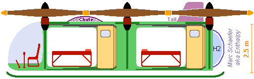
Oops, I'm late here... Here a suggestion of how the ambulance could look like (sections are odd, don't get fooled): It's tall enough that the medics can stand, and permits to walk around the beds. The doors could slide to the roof instead, if durable enough - check how fire engines do it. On this sketch the rotors lift the cabin by its floor. A dense truss to the landing sledge would strengthen the floor but prevent shock damping. As the rotors are not synchronous, they should be made as quiet as possible. Marc Schaefer, aka Enthalpy

-
I've just read that sodium and potassium can be obtained by electrolysis of the chloride dissolved in propylene carbonate. http://en.wikipedia.org/wiki/Propylene_carbonate It's a mass-produced compound (Huntsman has a doc) used in lithium batteries.
-
Europa is a big Jovian moon; prevalent models imagine beneath its thick ice crust a water ocean where wild scenarios put life. http://en.wikipedia.org/wiki/Jupiter http://en.wikipedia.org/wiki/Moons_of_Jupiter http://en.wikipedia.org/wiki/Europa_(moon) The Galileo probe passed by repeatedly; a special mission carrying recent instruments just to Europa has strong support. http://en.wikipedia.org/wiki/Galileo_spacecraft Europa's location (go to Jupiter, plunge to the 13739m/s circular orbit) challenges chemical rockets. A mission with fission reactor and ion thruster was abandoned. The Solar thermal engine achieves the performance naturally. A Falcon-9 shall put 3414kg at 2945m/s above Earth's gravity, using an added escape stage: http://saposjoint.net/Forum/viewtopic.php?f=66&t=2272&p=41436#p41436 after which nine D=4.572m Solar thermal engines add 5848m/s in eight days so 2132kg reach Jupiter in 33 months. Europa's orbit inclination opens two wide launch windows in 11.86 years. A bigger rocket achieves more; so do slingshots by Venus, Venus and Earth, which smarter people can evaluate. ---------- If believing my spreadsheet, a capture sequence with weak braking should pass as low as possible by the celestial body, to match the periapsis of the capture orbit and the final orbit. The benefit is real even with 400µm/s2. It needs a pass but higher than the targeted periapsis, at least when braking always against the speed; pushing forward or downward at apoapsis may change the optimum. EuropaWeakBrakeAtJupiter.zip 5.204AU to Sun let each engine consume 0.67kg/day and brake by 98mN, or together 414µm/s2 when arriving at Jupiter with 5643m/s, increasing as the craft lightens. According to my spreadsheet, they decelerate to 18535m/s at 712Mm from Jupiter's center in 97 days; 7.4 days more braking inject the craft on a 671Mm/13344Mm orbit with 120 days period. This uses 4020+306m/s. At the next periapsis, a long kick of 306+306m/s brings the period to 57 days and the apoapsis to 4287Mm. Combined, they consume 4938m/s or 699kg hydrogen, leaving 1433kg on the 671Mm/4287Mm Jupiter orbit. ---------- To target Europa and its circular 671Mm Jupiter orbit, multiple "short" kicks at periapsis cost 4934m/s or 470kg hydrogen, leaving 963kg. If pushing over 20% of the orbit's duration, it takes 390 days, not quite pleasant. Smarter people would probably brake by many successive slingshots at Europa, whose period is only 3.5512 days, or at the heavier Ganymede. This should save propellants AND time. ---------- Capture by Europa isn't obvious, because weak braking leaves a high apoapsis, but Europa's influence extends only 15Mm on the Jupiter-Europa line. The apoapsis takes time to lower, and meanwhile Europa moves much around Jupiter, so the still high apoapsis can become aligned with Jupiter, bye-bye. We can increase the engines' thrust so the apoapsis lowers quickly enough, but my estimates tell that the lower engine performance makes this option less good. The better option I've seen puts the capture apoapsis over a pole, where Jupiter won't eject the craft. This permits the polar orbit preferred for an exploration probe. The small needed North-South speed before capture, like 100m/s, results from a slightly tilted 671Mm Jupiter orbit. The approach would leave no relative East-West speed, hence waive its favourable interaction with the capture, but this looks globally favourable. EuropaWeakBrake.zip Braking 4.4 days before to 0.1day after the pass at 1.83Mm and 1821m/s injects on a 1.8Mm/29Mm polar Europa orbit. Few weeks suffice to the circular 1.8Mm (1800km) Europa polar orbit - little over Europa's 1561km radius. The sequence costs 855m/s or 64kg hydrogen, leaving 899kg. The engines weigh around 270kg; some could be jettisoned while lowering the Jupiter orbit. The tank for 2515kg hydrogen can be split; as a single D=4.1m suspended balloon, it could weigh 115kg and its surrounding truss ~120kg. ---------- 899kg, obtained from a medium launcher, is a nice mass for an orbiter with cameras and deep-view radar. Slingshots at Venus, Earth and Europa would increase that, enabling additional lander and diver. ---------- Encelade is also a Moon with an ice crust and supposedly liquid water beneath, this one at Saturn. A similar mission there looks feasible, with comparable speed requirements, but is more difficult due to the fainter Sunlight. Concentrators lighter than 1kg/m2 would help even more. Marc Schaefer, aka Enthalpy
-
D-Li does not produce the proper energetic particles for a booster. D-3He is doubtful as it expels less favourable protons. http://en.wikipedia.org/wiki/Nuclear_fusion#Criteria_and_candidates_for_terrestrial_reactions http://en.wikipedia.org/wiki/Aneutronic_fusion Produce 3He... only in faint amounts, and using much energy. p-Li looks like a candidate for a beam+target apparatus. D-D is much more easily conduced, it produces 3He and 3H that decays to 3He over decades. D is available commercially in big amounts, and D-D is readily conduced in a fusor: http://en.wikipedia.org/wiki/Fusor "just" a matter of produced amounts and consumed energy... Powerful long-term operation would also pollute through neutron activation.
-
http://en.wikipedia.org/wiki/Helium-3 obtained from decay of tritium, produced itself in nuclear reactors by neutron irradiation of lithium. Shortage of both tritium and helium-3 in sight, so new sources are sought by the nuclear industry, despite the present thread looking unprofessional. The Wiki articke cites existing and prospective uses but doesn't tell what the main ones are. Fusion in tokamaks and laser reactors is out of reach; capabilities of the Z-machine aren't widely public. I'd imagine that research tries to replace tritium with stable helium-3 in the boosters of nuclear bombs - I had suggested lithium but igniting D-Li is more difficult.
-
Hydraulic actuators fit well Linear Friction Welding after all (changed my mind) and can exceed 100Hz if needed, especially if they use rotating distribution valves aided by proportional valves in series to regulate the amplitude and the mean position. But a serious difficulty here is that tubes risk to collapse instead of transmitting the shear force to the weld location. So here's a welding appartus by melting; it's semi-automatic because there are 1800 tube ends. It's a MIG process. Two or few shell elements are fit manually around the tubes to guide the flow of inert gas and hold the electrodes in place; the rest is automatic. The fittings around the tubes can have for instance shallow grooves as gas outlets. Instead of moving a unique electrode, I imagine many (like 60) static electrodes are easier in the limited room. Each has its electric supply, and probably its mechanical feed. I expect all electrodes active at the same time would let the molten metal flow too much under gravity, but several can operate simultaneously to get a more symmetric seam. Standard pratices, like a few points before the continuous seam, are possible. Some tungsten electrodes can start the seam if better so. Instead of mechanically feeding the welding wires, maybe the material can be stored and brought liquid through hollow tungsten electrodes, which is more flexible since melting the base material is decoupled from supplying the feed, but this relies on tungsten not melting - it's cooled by liquid aluminium , but unfortunately not when starting the seam. This would apply to any MIG process; it's a confluence with TIG. The feed alloy must not segregate when liquid for long. Marc Schaefer, aka Enthalpy
-
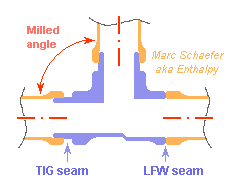
Linear Friction Welding (LFW) pushes strongly against an other the parts to be welded and shakes them sidewise until heat and movement forges them together, without melting. http://en.wikipedia.org/wiki/Friction_welding#Linear_friction_welding To weld, the shaking actuator must bring many kW over <1mm amplitude hence is quick, like 50Hz to 100Hz - more would supposedly be better. 100Hz is uncomfortable for the present hydraulic actuators; electromagnetic actuators first used are uneasy with the power. Starting instead from a rotation would permit to store energy for quicker release (this improves the weld seam) and use a higher frequency. 30kW*3s need few kg flywheel. A crankshaft can transform the rotation in the shaking motion, but to assemble the parts accurately, the amplitude must decrease to zero at the end. I suggest to revive the Stephenson valve gear for that. Here Emoscope's illustration, gratefully pinched at Wiki: http://en.wikipedia.org/wiki/Stephenson_valve_gear (click to see the picture move) The slide between the two rods is moved sidewards to adjust the amplitude of the top part, down to zero at the center. Here at a truss, it seems better to shake only the tube's free end and hold the truss node steady, so only one eccentric is really needed - with good balancing and adequate design at the slide, like adjusting the amplitude by sliding the arm's base rather than the connecting rod. The machine could catch the tube's end with one arm shaken by the slide and the node with a steady arm, connected preferably close to the crankshaft. Other uses may have two shaking arms of opposed phases, possibly driven by the same slide of proper design. One part or both can also receive crossed movements, say orthogonal and in phase quadrature, to shake with a circular motion that makes a more uniform cylindrical weld seam. Two crankshafts well phased, with at a part two arms converging perpendicularly to an other, achieve it. Other designs are possible. A crankshaft with eccentricity varying continuously along the axis, plus a de-biassing part, looks fragile to my eyes. A cylindre with eccentric hole that rotates around the crankshaft's handle and whose phase adjusts the amplitude is sturdy but not obvious to control. Easier: the rotation axis is parallel to the shake, a tilted disk transforms the movement, its inclination adjusts the amplitude. The Stephenson valve gear is well-proven. Its parts, movements and forces are sound. Marc Schaefer, aka Enthalpy
-
Trusses of shorter elements exploit slightly better the strength of a material of given stiffness. At the Esc-B sketch of message #38, two stages of 0.65m height would fit at each torus, and three around the ellipsoid's equator, with 2*30 tubes at each stage. This fits the capabilities of magnesium AZ80A; it also exploits better the aluminium AA7022, which is then as good as magnesium and more comfortable. Titanium is still uninteresting at this scale. Global buckling of the truss puts a limit on short (hence narrow) truss elements. I estimate it by assimilation with a uniform cylindre of same stiffness per length unit: only F=0.68*e2*E according to my experiment - simple theories are knowlingly false. I could not misuse Gerrit Wolsink's free "Framework" software to determine a truss' buckling; I plan to try with Frame3DD, and would gladly read proposals. ----- 1600 tube ends take long to weld. Turned tubes and separate milled nodes ease it and give extra thickness to the weaker weld seam. The tubes are turned to the proper thickness, leaving more near the seam. The inner diameter can be machined more accurate at the ends. The length is very accurate, the end faces as well. CNC milled nodes are affordable, light, and fit accurately the tubes' directions - the sketch is simplified, there would be six non-planar directions in a simple truss. They accept tubes just turned. Maybe some material at the center, plus a hole for one big screw, can hold the part when machining it. For Tungsten Inert Gas (TIG) welding, the groove at the sketch's left is a big help: it protects the back side without argon there, defines well the weld depth, and a shallow shoulder places accurately the tube's end. Linear Friction Welding (LFW) gives stronger seams, at the sketch's right. Can the truss be bigger than the welding machine? How shorter, and how accurately shorter, are the parts afterwards? To be checked. With the same parts shape, laser welding could be made portable and automatic. ----- If the skin is discarded by molten wires as suggested in the previous message, Ti-Al6V4 offers 828MPa, 7W/m/K @RT and 1.7µohm*m - a strong candidate that can be zapped by a 3V accumulator and semiconductor switches. Though, I prefer the electric motors. Marc Schaefer, aka Enthalpy