studiot
-
Posts
17639 -
Joined
-
Last visited
-
Days Won
93
Content Type
Profiles
Forums
Events
Everything posted by studiot
-
Why an Airplane Flies (Bernoulli's Principle vs. Newton's Third Law)
studiot replied to antimatter's topic in Physics
Why on earth (or in the sky) would you suggest this? The theoretical analysis of a phenomenon can often be approached from several viewpoints and calculated in several different ways. However they are always equivalent and compatible if they lead to the same result. Again, what line of reasoning leads you to state this? -
OK From the figures supplied. The area resisting detachment of the blue board comprises the 4 blocks 4 (3x10 =30 sq mm) plus half the long strip attached ie (3 x 80 = 240 sq mm) This makes a total resisting area of 360sqmm. All of this is in single shear. You say that the shear strength is 18 N/sqmm so total resisting capacity resisting detachment of the blue board is (18 x 360 = 6480) N. Resisting the blocks pulling away is (4 x 30= 120 sqmm) plus in tension = 2640N plus the other half of the area of the strip in shear = 18 x 240 = 4320N making a total of 6060N There are quite a few ifs and buts about this however, since the distribution of the 50N force is not known and no moments have been checked. Further the strength of any glued system is dependent on the quality of workmanship and subject to considerable variation and can easily delaminate under vibration or flexing. Are the strengths quoted the stength of the bond or the strength of the glue? You need the bond strengths, and I have assumed these are quoted in the calculations.
-
Definite Integration (Physics problem, sort of)
studiot replied to lightburst's topic in Analysis and Calculus
In your problem you are given force as a function of velocity and asked about distance. Now velocity is a function of time, as is distance. So at any time, t, the particle or whatever has a specific velocity, v, and covered a specific distance, x. So t is the common variable running through the maths. If you know the time t you can calculate the velocity and therefore the foce, and the distance covered using the formula by substitution or change of variable. When you change the variable or substitute you also have to change the limits of integration so that if you are integrating say velocity between t = 0 and t=10 you need the velocity at t=0 and t=10 if you use a formula involving v not t. -
Well yes, I can "do calculations" but I am still not clear what you are trying to achieve. I really would like to be sure that any calculations will be of some value. Are you trying to make a mechanical repair or strengthening to the grey board or Are you trying to add a piggy back electrical board to repair the electrical circuitry or add further functionality? These are two very different situations with very different mechanical requirements.
-
As I understand your intention you wish to repair the grey board by gluing the blue T shaped splint to it. Is the grey board cracked or broken under the blue? Can you not simply glue the large flat faces together? The four brown wedge shaped pieces are a reasonable fixture, but why bother to cut the wedges, why not just use rectangular section? The problem with edge fixing is differential movement between the grey board and the blue, particularly die to flexing. I see you attempting to address this with the by gluding on a flat edge strip. This is unlikely to hold for long. Does the blue board carry circuitry and tracks or is it just a mechanical splint? If you can drill through both boards a various places and provide through rivets, perhaps with soldered links, this would be a better solution.
-
Definite Integration (Physics problem, sort of)
studiot replied to lightburst's topic in Analysis and Calculus
Yes this is sort of true, but presents a problem. The differential coefficient on the LHS is in terms of v (ie dv) and on the RHS in terms of t (ie dt) Yes you are integrating between the same two endpoints but one is in terms of t and one in terms of v and you need to match the differential coefficient and limits in your integral. Of course v and t are connected by an equation as are dv and dt -
Space has no time. No beginning No end.
studiot replied to mattrsmith88's topic in Astronomy and Cosmology
You need to be very careful with this concept, as soon as you use the word 'expand'. Perhaps you would like to explain further? -
Space has no time. No beginning No end.
studiot replied to mattrsmith88's topic in Astronomy and Cosmology
You know of mathematical structures that have no boundaries, but are limited or finite. Absolute temperature is one such. The surface of a ball is another. -
Hello koii, Is this homework of some sort? You need to start by considering what you mean by 'gounded', which is an electricalengineering term, not a structural engineering term. In particular your fig3. Which way do you think the forces are acting? Then please say what you man by a 20N uniform force. Do you mean a total of 20N uniformly distributed or 2oN/linear m of block or 20N/ sq metre?
-
This thread is to offer the opportunity to share clever quotations that people have come across. To kick off here is one from Professor Inglis
-
Why an Airplane Flies (Bernoulli's Principle vs. Newton's Third Law)
studiot replied to antimatter's topic in Physics
To me, the most eloquent enunciation of this principle was "Gentlemen, shall I refuse my dinner because I do not fully understand the process of digestion ?" -
Or you can turn this the other way round and observe that alloying materials harden a material eg the addition of carbon to iron to make steel. Impurities are also known to be an impediment to dislocation spread. But what was your question? Edit : Have you also thought about the transition temperature?
-
Since this query now appears genuine a comment or three. 1) Swansont has told you that it is not possible for heat to flow from a colder body to a hotter one (without an external agent). So your plate cannot ever get hotter (reach a higher temperature) of its own accord than the stove hotplate. The only way I could see some overshoot would be if the heated plate was insulated, but the heating plate had a much larger uncovered area so whatever was heating the heating plate (which is obviously at a higher temperature than the heating plate itself) was pumping heat into a local variation of temperature. In other words the heating plate was actually hotter in some places than others. How do you know that your sensor was measuring the temperature of the heating plate at the contact surface with the heated plate, rather than at some other colder part of the heating plate. 2) The actual temperature recorded by a sensor will depend upon the (thermal) coupling between the sensor and the object. 3) Sensors, especially thermocouples, do not have a fast response time. This needs to be allowed for in measurement recording.
-
Hint look up osmosis
-
Sensei has offered a good method of studying the magnet, but not the electric part. However, have a care here. The point of the compass needle that points to the Earth's North Pole is actually the south pole of the compass needle magnet. It is often called a 'north seeking pole' as a result. The part of the Wiki article called "how a magnetic compass works" explains this.
-
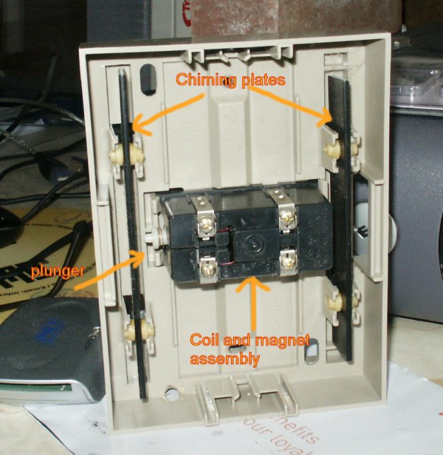
Hello chris, One problem is that you need to wind a large number of coils to achieve an observable effect without special equipment. Why are you using an iron bar? This is normally used to concentrate the magnetic field generated by an electromagnet. You do not gain anything by trying to energise it with a permanent magnet. In order to generate a voltage you need to take the iron bar away and move your magnet back and fore along the axis of the coil windings. A good apparatus to study this is the inside of an old house doorbell, as in the photo. The white plunger is mounted on a magnet and sent side-to-side when the bell switch is closed allowing current to flow in the coil, generating a magnetic field. The upright black metal plates are freely mounted so that they vibrate audibly when struck by the plunger, a bit like wind chimes. I have removed the batteries for clarity. You can also create a voltage at the terminals by manually moving the plunger side-to-side. this can be measured with a voltmeter or used to illuminate a small bulb (not an LED).

-
All magnets are polarised and have two poles, so try and explain your question more. From the looks of your picture your magnet would work better at right angles to its present position. The poles are usually at the narrow ends and the magnetic field is strongest near the poles.
-
Preferably a hoop painted on a brick wall.
-
Not really You have the basic equation [math]F = \mu R[/math] It doesn't mater whether we are talking static or kinetic here. Your attempt to account for the mu factor works on summing all the contributions from F. The plastic theory works by summing all the contributions from R. You do not need to do both, just one or the other. Plastic theory suggests that [math]{\mu _s} > {\mu _k}[/math] simply because the bonds don't have time to fully form before the surfaces move on. You should also note that sinx is never greater than 1 so the product of two sines is smaller than either.
-
Really? For steel, Youngs modulus is 2 x 10¹¹ N/m2 Modulus of rigidity is 0.8 x 10¹¹ N/m2 Thus the plastic approximation to the coefficient of friction is 0.8/2 = 0.4. Pretty close I'd say.
-
Why an Airplane Flies (Bernoulli's Principle vs. Newton's Third Law)
studiot replied to antimatter's topic in Physics
That's clever how does that happen as it is flying along, icing? If you look back at Bignose'e post you will see he mentions circulation. This has physical dimenstions L2T-1. Multiply this by the mass within the circulation countour and you get the ML2T-1, which has the dimenetins of moment of momentum. Yes this circulation is going with the stream over the top, down at the rear, against the stream underneath and up in the front. The rule is The thrust at right angles to the flow acts from the side where the circulation and uniform flow oppose towards the side where they reinforce. Hence the lift. -
No offence meant Delbert, but their difference would not be the subject of a physics exam or homework question if they were. Look at the wording of the question, "distinguish between......" that is examspeak.
-
That is a very good question, except that you have not posted any actual thermocouple readings. Certainy 'accepted practice in the lab' sounds more like a practical joke than a thermocouple reading.
-
Is this an exam question? A lot of folks are doing physics exams at the moment. Here is a hint, to explain the difference you should think about energy, both energy sources and energy sinks (dissipators).
-
OK, plastic theory works like this. Take an irregular (bumpy) horizontal surface. Because it is bumpy it must have a highest point Now place a second perfectly smooth flat surface onto the bumpy one. I am only using a flat second surface for simplicity of explanation the pricciple is the same for an irregular surface. Clearly the flat surface will touch the highest point of the bumpy one first. Now the stress equals the contact force (weight of the second object) divided by the area of contact. But this area is very small. So the high point will deform plastically until contact is made with the second highest point. And so on to the third, fourth etc highest points Until the area of contact is sufficient to support the contact force without further deformation. This plastic deformation joins (bonds) the two objects across the area of contact. Breaking this bond requires a shear force equal to the frictional force calculated from the coefficient of friction. I do not have the time tonight but you can derive that [math]\mu [/math] [math] \approx [/math] [math]\frac{{{S_s}}}{{{S_y}}}[/math] That is the coefficient of friction is approximately equal to the ratio of the shear strength to the yield strength.