Enthalpy
-
Posts
3887 -
Joined
-
Last visited
-
Days Won
1
Content Type
Profiles
Forums
Events
Everything posted by Enthalpy
-
Torque can't be determined from the dimensions, so don't hope for a formula. What you need to estimate are friction and other losses. Or the inertia moment in case you need a huge acceleration - probably not. Or weight's torque in case the rotation is very eccentric and the axis not vertical.
-
For embedded cracks, you might consider ultrasound. In rods D=25 L=310, you can inject a pulse at one end and check the reflections. It needs a clean source of pulse (or possibly a wideband continuous source) which implies good impedance matching at both ends. This needs ideas if you're to change the rod quickly. Or repel the rod's end with a magnetic pulse? Lithotriptors have such actuators. It can be the sensor as well, in a DC magnetic field. If working with short pulses, which seems more common with the ultrasound community, you can stop listening when the echo from the remote end of the rod arrives. Then, it could be better to inject the (possibly shear) pulse at the rod's center rather than at one end. The microwave community uses rather a reflectometer, which works on frequency-swept continous signals, and relies on directional couplers and heavy signal processing to detect faint echoes at precise locations and discard stronger ones, in your case from the imperfectly matched rod's remote end. If reflectometers already exist for ultrasound (I ignore it), use one; if not, it's too complicated to develop for your project. ================================== A different method depends on the cracks behaving non-linearly on sound - which I suspect but have never experimented. This method may be original, in which case you'd have to develop it. It's essentially the way magnetic anti-theft stripes are detected on goods at store's gates: a very pure sine wave is emitted, and a received detects if a harmonic is produced by a non-linear item. The harmonic is chosen odd (3, sometimes 5) for magnetic stripes because their nonlinearity can be an odd function, but cracks may well bring an even nonlinearity. Sine functions are used because analog electronics means can produce them extremely pure and filter them with a huge linearity and selectivity: my detector for magnetic anti-theft stripes had over 140dB linearity, which isn't attainable by an analog-to-digital converter, preventing any subsequent digital processing. With this method, you might perhaps couple the (ultra-) sound by immersing the rod in a bath, provided the bath's surface behaves linearly enough. It needs linear transceivers as well, so check if ceramics achieve that. Resonating the rod mechanically, for instance at its first bending frequency, or at some compression or shear resonance, would add filtering for free, and this would not rely on the transducers' linearity. Bending is less good to detect cracks at the rod's ends. I used few kHz, with active filters and audio amplifiers, but higher frequencies enable passive filters (LC, lines, cavities...) after the power amplifier and before the harmonic amplifier. Use no magnetic core. Polypropylene and type I ceramic and air capacitors are linear. Only a good analog electronics designer can do it. Good luck. Marc Schaefer, aka Enthalpy ================================== Over 10 years ago a Belgian small company offered tiny X-rays tomographs with faint resolution. They may cost a bit, but would fit your D=25 rods, and development cost is zero for you. A tomograph will show you cracks, while a simple X-ray picture is difficult to intepret. A different technique, which was recent 10 years ago as well, used sound propagation. Originally, a short laser pulse creates the sound in the target metal, and an other laser beam senses the target's movements at a different location, so no contact is needed. One funny idea is that the received reflected light is subtracted from itself with a delay, so that only the target's speed varying faster than the delay are observed, the rest being attenuated, and the reflection's intensity isn't essential.
-
Thanks Klaynos, and yes, please tell us more! ================================================== I had written previously "the image's autocorrelation" and this was oversimplified. Rather, something like an autoadaptive filter should run on the image, for instance a Kalman filter, to obtain first the positions of the nanoparticles. Then, the correlation between the raw image and the filtered one gives the diffraction pattern, accumulated over many particles. Or maybe the proper programmation of the autoadaptive filter gives the diffraction pattern directly.
-
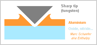
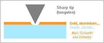
This is how I imagine a narrow hole in thicker aluminium: If the hole is punched by pressing the tip through very pure aluminium (which is ultra-soft), the harder ceramic stops the movement, and this defines a narrow hole. The other previously suggested processes must work as well. Immediately around the hole, aluminium isn't very opaque, but enough to define a diffraction pattern; farther away, it's thick enough to avoid background light. Marc Schaefer, aka Enthalpy ================================================== What is the desired distance between the gold dots? I begin to realize that, because the dots' luminosity or opacity is faint as compared with stray light, opticians will probably use many dots at a time. That is, they would have an eyepiece and CCD that give many pixels within the objective's diffraction limit, collect the diffraction pattern around many dots in the field, and have a software compute the image's autocorrelation to obtain a clear objective's diffraction pattern from many noisy patterns around each dot. For that purpose, they would prefer the dots on an irregular pattern, and I'd say, the distance between the dots should better be greater than one diffraction pattern diameter, which must be seriously bigger than 20nm. Is a mist of hydrofluoric acid, with droplets 50nm wide, any conceivable? They might etch tiny holes in glass. I hope a single tiny hole illuminated by the very concentrated light of a DVD burner laser diode and its lens does not need this software data processing. Maybe Ka Ho could tell us more about this? Marc Schaefer, aka Enthalpy

-
I don't have my Handbook of Chemistry and Physics here... Got data there, hope it's correct, telling that: http://refractiveind...erial=Aluminium - Aluminium is better than gold in the visible spectrum - 20nm of Al leave 7% at 800nm, 5% at 400nm and 6% at 171nm. Hole definition is efficient, background light is too strong, you're right. BUT we can have a thicker layer everywhere and leave it thinner locally to keep the contrast. For instance, if the hole is made by pressing the tip through the soft metal against the hard ceramic, then a conical hole can be narrow at the bottom (let's keep D=20nm) and wider at the top. At 90° full angle, only D=60nm have <20nm thickness, and D=100nm have already 40nm thickness, and so on. This looks simple and acceptably efficient. Marc Schaefer, aka Enthalpy
-
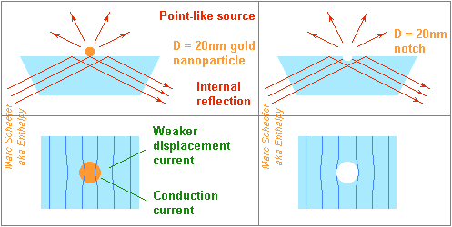
Thanks for your interest! What helps us is that attenuation is already strong through 20nm. Our eyes have such a huge dynamic scale that we notice just a significant change for an intensity ratio of 1000. As for general background light, the film can be thicker farther away from the hole. So I'd stay away from high aspect ratio holes and grooves, which semiconductor processes do regularly but are tricky. ============================================================= Gold nanoparticles can frustrate locally a total internal reflection, acting as point-like sources over a dark background: this is far better than shadowing uniform light, and must be the original poster's intention. I feel it less good than a notch in a metal screen, because in the transparent material, the displacement current d(D)/dt concentrates before entering the nanoparticle, stretching the radiating zone, and dilutes at the sides, reducing the radiated field and sharpening its pattern. As the conduction current is nearly compensated by nearby displacement current dilution, the particle's protruding position must be the main contributor to radiation. Surface smoothness elsewhere must be far better than 20nm. Semiconductor processes have worse requirements. A small notch in the reflecting surface has nearly the same effect as a gold nanoparticle. I'd try the already suggested methods: mechanical action of the tungsten tip; local electric current from the tip, which may bombard the surface with H and F ions alternating... Because total reflection puts limits on the angle of incoming light, a lens can't concentrate light as strongly as on a punched screen. A monomode fibre carries concentrated light, so a small notch there radiates more. Bigger notches are made for fibre gratings. The fibre should be cladding-less (¡Ole!) or maybe have a soft polymer cladding over a hard ceramic core. Alternately, an optical chip made by semiconductor processes can have a light guide with a notch (20nm being a present-day size), and allows a protective cover. Nice compact source, especially if the laser diode is integrated. But I prefer a small hole in a metal screen covering a laser diode. Marc Schaefer, aka Enthalpy
-
It has been shown experimentally to work with a rotating body of molten metal. Few years ago, at Ecole Normale Supérieure de Lyon.
-
"Large amounts of water in its crust" doesn't meant three global Oceans!
-
I do agree with the field in the gap. Permanent magnets facing the gap can produce it, or a coil running in the void of the iron. This field in the gap produces a (strong) torque on the mobile magnet. No spontaneous movement will result, because the mobile magnet would experience the same flux from the gap after it has moved. Magnets feel a force when their movement permits to align magnetic fields, ar change teir cumulated intensity, etc. So this won't make a perpetuum mobile. The hidden reason is that the mobile magnet produces not only a torque, but also a tangential force, which compensates the effect of the torque on the axis. This is difficult to see with a permanent magnet, but easier with a single flat rectangular current loop in the gap. The current in this loop near the inner pole of the gap feels a more concentrated flux, that is a bigger induction, than the current near the outer pole. The force ratio equals the radius ratio. Being different, they don't cancel out, by a factor being the relative difference of the radii. Now, the torque produced by this current loop is the product of this force by the distance between the currents, so the force at the axis is smaller than each electromagnetic force, by a factor that equals the relative difference of the radii, too. The global effects cancel out. You can imagine a permanent magnet like many small current loops composing its volume. Every small current loop produces zero net movement. Fun.
-
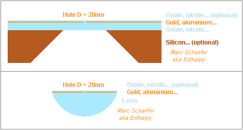
The stack with the punched metal layer may look like this: The optional transparent layer is harder and shall protect the metal. If the other transparent layer carrying the metal must be thin, it can be a membrane supported by thicker silicon for instance, which may be locally etched away before or after punching the hole. The light source can be above or beneath the hole on the sketch. Several holes can be made, possibly on a pseudo-random pattern. In the option at the lower part of the sketch, the same transparent part that holds the metal film can be a lens as well, to increase the light power density at the hole. Tips sharp to one atom are made for tunnel and atomic force microscopes, historically by breaking tungsten: and offer several methods others than a beam of electrons or ions (fluor?) focussed at the metal film to punch it: - Mechanical force - Local flux of electrons or ions (fluor?), not needing to focus - Anodize - Evaporate the metal. How the current flows over this distance isn't essential to distinguish: field emission, whole distance tunnel, surface conduction, arc... But its dependance on distance defines a precise hole radius, especially if the voltage is limited. Spherical heat diffusion in the transparent material helps define the hole's radius. Punching in vacuum is one option, an other is a gas or even a liquid, for instance SF6 or CF4 or H2O, to etch or anodize the metal layer. Marc Schaefer, aka Enthalpy


-
2-3 years ago an experiment was started in Italy to check if a magnetic field in vacuum would rotate even a tiny little bit the polarization of light. Since then, no result, so it must be negative despite the sensitivity.
-
I wouldn't replace water at all! Please show me any oil that cools as well as water does. Then, tell me how flammable a thin oil is. And why should a thin oil boil less readily than water?
-
Pour hydrogen peroxide in your saltwater solution, that will go faster. Use some way to decompose it. Estimate the amount and concentration to obtain a bit more than said 8ppm. http://www.engineeringtoolbox.com/ has tables of solubility somewhere.
-
Keep a stable and uniform composition at prolonged heat, not degas... Be a good lubricant so the pump lives long, and that's difficult. It needs a good viscosity at high shear numbers, among others. Wet solids easily. De-foam quickly. Allow long storage, preferably at air and at cold as well. Flammability isn't easy to check. High pressure leaks can build a mist. Heat makes it worse. If you consider glycol, please prefer propane diol or polyethylene glycol. Simple glycol is a poison that tastes sweet. Put together, using a known hydraulic fluid like Hydrolub as a cooling fluid looks easier and safer (but this one doesn't insulate). Do NOT replace transformer oil by anything else in electrical uses: it's highly optimized as an insulator. Any other liquid will fail, possibly after months of operation, with BIG consequences. If water was needed for its performance, replacement is nearly impossible. Put additives, at most.
-
Sorry for the sideslipping answer, but... Semiconductor technology can make a hole of 20nm diameter for you. One single 20nm hole in an opaque screen. Through standard patterning techniques, or maybe by punching the screen with an electron beam. One hole in a screen brings you the same optics interference pattern and intensity as one black point over a luminous background, except that - You avoid the luminous background, so the optics' interference pattern is much easier to observe; - You can concentrate your light source on the hole, so the optics' interference pattern is brighter. Alternately, you could let produce a single gold dot by an atomic force microscope, for instance at IBM's research centre in Zürich. Then, less than 20nm would be better. Perhaps you might consider a very thin metal layer on glass (like 20nm by evaporation) and punch a hole in it with a (small!) sparkle from a needle. Use weak currents and a micropositioner; corona effect, or even tunnel, tell you the distance. Early tunnel microscopes used a needle of broken tungsten to get a single atom tip. And what about a space blanket? Their aluminium film is very thin and uses to have already holes. Just choose the hole you prefer, and infer its size from the amount of transmitted light. Their stack is: thicker clear polyester - aluminium - coloured varnish. You may add thicker varnish to protect the best hole. Is your optics meant for semiconductor lithography? ============================================================= One more bizarre idea, again without colloidal gold, sorry for that... Take two thin tungsten wires, like 20µm diameter. Hold them taut by their ends, cross them without pulling them much together. Verify that their contact area is 20nm wide by measuring the cold resistance from one wire to the other : the contact resistance must be equivalent to 5mm length of 20µm wire, which 2+4 resistance measures tell independently of where the wires touch. A small current may be first needed to obtain a stable contact. Put that in pure argon, inject current to let the tiny contact glow, you get a light source of 20nm diameter, emitting white light to the sides. Drawback : it's only 2nW at 3300K. And it may need 1/2W electricity, which brings the wires to ~1100K away from the contact, shining a bit as well. Thicker wires would improve that. The contact point doesn't get a constant voltage because of the series resistance, and this is bad for its life expectancy; again thicker wires would improve. Make a new contact at a further location is one becomes too wide. ============================================================= Back to the holed thin metal film. Several metals like Au, pure Al, Ta, Nb... resist oxidation even in 20nm thickness, and can be coated with SiO2, Si3N4... Au and Al have an interesting opacity (and the film can be thicker); uniform films that thin are obtained by semiconductor processes. The substrate holding the film can be silica, sapphire... If it must be <1µm thin, it can be a small membrane of SiO2, Si3N4... supported at its periphery by a thicker silicon chip. To open the hole(s): Maybe the micromanipulator with the sharp tungsten tip can punch the hole by mechanical pressure. The electron beam of course. Anodizing (20nm)3 Al, Ta, Nb to transparent oxides takes ridiculous amounts of electricity, like 80fC, or 4V through a 20fF stray capacitance. Hard to insulate and control. But one might implant oxygen locally in the metal by a focussed ion beam. Vaporizing aluminium between the tungsten tip and an alumina substrate. It may take some 15mW of electrical power, where many radius-dependent effects cooperate to define a precise radius. A constant voltage (or a constant voltage limit) may improve further. To illuminate the hole: Erbium-doped fibre lasers for datacom repeaters can inject up to 10kW at 1300nm in a monomode fibre. Even a bearable power density leaves a lot on D=20nm! Laser diodes provide several mW at 780nm (for CD burners), 635nm (DVD burners), 405nm (blu-ray burners). The holed metal film could be deposited on the laser diode for ruggedness, or at the focus for power: a blu-ray burner concentrates several mW to D=290nm. A holed metal film on a laser diode, possibly with a lens, looks compact and convenient, so it can become a catalogue component if enough customers want it. Marc Schaefer, aka Enthalpy
-
Expand CO2 in an engine.
-
Delta-V for "direct descent" to the lunar surface?
Enthalpy replied to Robert Clark's topic in Physics
Hi Robert, nice to see you here! The delta-V should not differ if you make a stop on a low orbit. The only difference lies in the Oberth effect, where the additional energy you put to reach the transfer path is added at the speed of the low orbit, instead of possibly at a marginally higher speed if the push is done at a slightly lower altitude (measured from the planet's centre). So if you get a difference, I expect some unclear data lead to misinterpretation. In any case, keeping the return vessel in Lunar orbit is an excellent choice, one that made Apollo possible, because then you save the mass of the return vehicle (and fuel) from your Lunar descent-ascent module. This makes a huge difference, much more interesting than 360m/s. Remember Wiki's table gives minimum speed increments, but in a real mission you wouldn't choose a lengthy Hohmann transfer. A few 10m/s more cut the transfers by several days and are the normal choice. -
I need suggestion regarding my master thesis topic
Enthalpy replied to fiz's topic in Computer Science
I (and other people) would badly need one piece of software, but maybe it's too easy for you... One that tells if a particular application can run on a particular OS - which means in essence, if the desired entry points can be made available to this application. This would be useful for drivers as well as applications; it often happens that they're tested only on recent OS but are able to run on older ones - or that the editor or distributor claims a wrong compatibility. This software would be good for programmers as well, as they would get an opinion about their product's compatibility, and maybe hints to enlarge its compatibility. Optionally, it would be great if the software could make an opinion right by checking the application's installer, instead of the installed application. Not absolutely necessary. And one more difficulty is that some installers choose the files according to the current machine - or even, some applications test what OS they're presently running on, to call only the available entries. You also have for instance nVidia drivers officially meant for W2k that bring a good video driver but install a PhysX that doesn't work. Also seen: the application would work but its installer doesn't. I believe diagnostic failure is acceptable in such cases. Similar ones exist, but not the one I need. Most check if the application's function calls match the ones available in the current OS, but: - I want to check from my online W2k or Xp if the application will run on my offline Win95, for instance; - If just an update of DotNet or a runtime is needed, I want the software to tell me that, instead of "not presently available"; so this software should compare the desired entries with a knowledge base, not with the presently installed OS. In case of incompatibility, the number of missing entries tends to be fairly large, so I wouldn't like a complete list of them, but instead a synthetic answer, like: "the minimum is Win98 or W2k because dX9.0c is needed" or "on this current Xp yes, provided you add DotNet 3.5". To make it slightly more subtle, different updates or add-ons can bring the same functions, for instance ie5.50 brings to Win95 a vast collection of individually available updates. Maybe the user could tell more precisely what already composes his target OS to get an incremental answer, or the software may ask "will you put ie5.50?". I'd like easily read and modified knowledge bases, like one text file for each OS and update module, to tell what entries are available and what modules are possible, because: - This software must evolve a lot over time; - Experience tells some modules run perfectly on OS not officially compatible, so the user should be able to update that; - Sometimes, users port libraries not initially meant for one particular target... - The same software may be useful for Linux, Mac... and easy data format would help to port it. Such knowledge bases would better be created automatically, though hand editable. This project is simple, but less so than it looks, and demands several months to one person. If you want to write this software, thanks in advance! Marc Schaefer, aka Enthalpy -
Mechanical engineering would need a software that converts automatically 2D CAD drawings into 3D models. That is, 10 years ago, many technical drawings were made as 2D, which is essentially the same as paper design aided by a computer. These drawings still exist, are used, but get old-fashioned, with the associated drawbacks. Computer-Aided-Design is presently done in 3D, which means that the software gets from the designer a 3D description of the parts; 2D views and cuts (for paper prints...) are extracted automatically from the 3D model. Engineering companies would need to convert the old 2D files to 3D models but this means a big investment in designer time. An automatic conversion would be welcome. Asking a human to help the software is perfectly acceptable if not too often and in a bearable manner. ----- A 2D technical drawing is supposed to contain all the information to represent the parts, but this has first to be understood by a software! Many rules are used to read a drawing. In addition, some information is implicitly re-created by the reader even if he isn't aware of it: one single diameter indication would qualify 10 identical holes without telling which ones, for instance. This projects needs no machine learning, but the amount of expert knowledge needed by the software, plus some necessary interpretation, dictates to program it by artificial intelligence techniques. To be accepted, the conversion software must necessarily use commercial file formats. ----- The size, and maybe complexity, of such a software exceeds an MSc thesis to my opinion. But if one plans a following PhD, maybe a limited demonstrator can make an MSc thesis, for instance working only on parts with cylindrical symmetry, starting from sagittal cuts only. You can add features as the project advances, like reading the combination of a sagittal cut and a polar view. I suggested this idea elsewhere several years ago but have heard of no implementation, so it must still be new. If you're interested, best wishes! Marc Schaefer, aka Enthalpy
-
Japanese universities and car makers investigate it, but with a better metal than lithium - do I remember it's magnesium? Which, anyway, looks meaningless to me. Using the metal in a chemical battery to power an electric motor is better than converting the metal to hydrogen, as this existing technology is the most efficient one. Just replace the (primary) battery at the gas station and recycle it.
-
Efficiency improves if you use the motor's waste heat for your own home. Some farmers run their engines on home-made biodiesel to save money, without subsidies for it, despite they wouldn't pay taxes on normal Diesel oil, so the economic comparison must shift a lot under certain circumstances. It also tells that farmers don't consume much carbon-emitting energy to produce biodiesel - to the least, they can use biodiesel in this first step a well, and need less than the produced biodiesel.
-
Need help from Electrical Engineers Please! (CFC60 and CFC36 reqs)
Enthalpy replied to WCIGAFETW's topic in Engineering
I suppose it's the attenuation in the stop band. Your biggest difficulty seems to be that your software uses bizarre terms which are not the vocabulary of filter specialists. Also, to specify a low-pass filter, it needs the frequency where the stop band begins. You should not take a Butterworth filter for acceleration data. At identical selectivity, it's the one with the worst step response: it rings (oscilates) horribly. Checychev is better, elliptic even better, and among known names, the inverse Chebychev (or type II Chebychev), minimum-Q-elliptic, and hourglass are good. I know this is not the common opinion, but all other people are wrong because they compare at identical number of poles, while I compare at identical selectivity. -
Aluminium is but better than sand, and graphite is worse. Solar thermal power plants use molten nitrate salts. But for sure, a hot liquid if more dangerous than a hot solid, and hot nitrate spilled over a combustible material... What if you heat soil, and let air flow through it later, to harvest the heat? Use separate tubes to avoid bad smells. Or heat the walls of the home. Or heat stones of reasonable size, which you can carry individually in the home. Then, technology brings only the suitable tweezers and the insulated container. You still need to avoid bad smell.
-
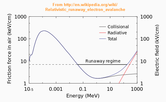
Changed my mind - on nearly everything... Relativistic electrons can already propagate where the field is insufficient for usual breakdown. So if cosmic rays were the feeds for relativistic electrons, X and gamma rays would be diffuse around a thunder cloud and not synchronized with lightning. Then, the tip of a bolt's leader concentrates a huge field, because the tip is narrow and the propagating bolt brings the high potentials nearer to an other through its short-circuit. Though, normal avalanche electrons (20eV) are slow, and these corresponds to the propagation speed of the leader. The huge field suffices (from 20MeV up), and the locally available voltage as well, to let normal electrons jump into the relativistic valley and propagate away. So, the bolt's leader is a perfect source for these electrons. Relativistic electrons won't multiply much. Over 1MeV their collisional friction is only 0.2MeV/m, which creates electrons of varied energies, while 0.1MeV in the proper direction would be necessary for a new relativistic electron in a runaway (the rest of friction produces photons). Even if they multiply a bit, as they propagate in one direction, they would need other particles to propagate backwards to sustain an own discharge path. Positrons can't multiply by impact ionization of atoms and are likely to disappear before having travelled kilometres back, so they're bad candidates. In short: the normal bolt's tip produces relativistic electrons, these don't multiply much, can't sustain an own discharge path, and create energetic photons. This view resembles what Wiki and a paper from 2010 claim: http://en.wikipedia....ctron_avalanche I'll reference the paper when I find it. ================================================ An experiment reproducing 60kA*1µs from the first strike in a bolt but reduced to 1MV needs only 30kJ. An assembly of commercial capacitors can store this energy, for instance: http://highenergycor...|1002|1013|1017 50 of these fit in 1.7m * 1.3m * 0.5m. This particular capacitor model or an other may deliver the 60kA, depending on its internal gathering electrodes. A diode-capacitor pump to charge them can use rectifiers and a few transformers made for CRT screens. The slow charge is meant to reproduce the lightning conditions; a Marx generator would apply the voltage brutally on the air, different choice. I imagine the gamma source in a tube with an integral bottom and a removable cap (possibly remote-controlled), a layer of 90Sr at the bottom, covered by a layer of 40µm of aluminium (for instance) to stop betas below 100keV, then a fine-meshed honeycomb in the tube to select the desired beta direction over a short distance. The discharge tube must be corrugated as insulators are, but internally as well. The anode must be hollow and deep to brake the electrons in air. One mobile electrode would be nice. The tube contains the X-ray detector and can be submerged in transformer oil or surrounded by concrete. ----- The Z-machine is said to produce more X-rays than expected from striction; maybe relativistic electrons in the discharge contribute. To enhance this effect, replace the thin wires of tungsten or steel by a light element like lithium or deuterium, and add an anode of a heavy element like tungsten. Marc Schaefer, aka Enthalpy

-
There is no threshold at all: the response is linear, that's why piezo materials make extremely sensitive sensors of force, pressure, acceleration... Quartz is less efficient than other materials but serves sometimes as a precise reference. Piezo materials also serve to make electric frequency filters (and oscillators); I used one at -124dBm or 4*10-16 W and it worked as expected - this tells there is no threshold on tiny signals and forces and deformation. The linear response enables a tensor to represent it. The free flow of current in a short circuit means no voltage stands. The resulting movement of charge changes the mechanical behaviour of the piezo material - a bit with quartz which is NOT commonly used, a lot with PVDF.