Hello everybody!
A less known attempt to D-T fusion, apart from laser compression, Z striction, and tokamaks, is magnetized target fusion, where a magnetic field confines a plasma, and increasing quickly the induction - typically by squeezing some conductive rings and the flux in them - increases the plasma's density and temperature to ignite fusion, and hopefully harvest more energy than was invested.
After a naval lab explored this approach few decades ago, a company in British Columbia called General Fusion wants to try again, with a design that combines many nice features. Their description begins here and spans several clear pages:
http://www.generalfu...m/overview.html
One of the hard points is that they need the ~200 hammers to impact at 100m/s with a precision of 1µs. While this is seriously difficult, I suppose it is possible, because we managed similar movements with a precision around 100µs using actuators that had 20ms response time, at a company where I developed hardware for crash-test.
Here are some enabling technologies I imagine for their design.
---------------------------------------------------------------------------------
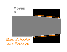
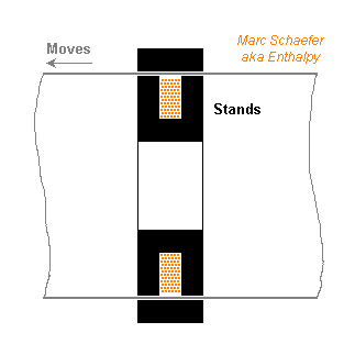
Pneumatic force propels their hammers (though I like hydraulics better). Because opening a big pneumatic or hydraulic valve in much less than 20ms is difficult, and because General Fusion's big hammers need a significant fluid throughput, I imagine we can lock the hammer, establish the hammer's driving force, then unlock the hammer quickly - here's my unlocker.
The hammer has some slowly conical section. The hammer is run backwards with a moderate force, it must wedge into the conical unlocker. The unlocker is thin at the contact area with the hammer, so hydraulic pressure put then deforms the thin part which presses the hammer and holds it by friction. Following, the hammer driving force can be established over a convenient time, and the hammer is released suddenly by releasing the hydraulic pressure from the unlocker.
Releasing the hydraulic pressure is swift because the volume is small. This is an example with 150kN driving force on the hammer:
Friction coefficient must guarantee >0.2, for instance nickel plating or aluminium bronze have about 0.4.
Hydraulic fluid at 350b acts on the 3mm thick membrane, which has D=74mm L=100mm.
The stiff fluid, like Hydrolub, is only 1mm thick, so pressure shrinks it by 0.5cm3.
Steel around the fluid is 20mm thick, its strain absorbs further 0.5cm3 of fluid.
Releasing 1cm3 of fluid at 350b in 1ms needs just over 4mm2 valve opening - now that's easy.
Details:
The cones' angles must match precisely. Cylinders are possible with precise diameters.
The hammer is probably guided elsewhere, so the unlocker must float laterally.
The matching surfaces must be clean. The hammer must be present before locking pressure builds up.
Bring locking pressure through a tiny permanent hole, or through the "lock" position of the valve.
The valve may be rotative or translating; a voice coil motor can move it.
Marc Schaefer, aka Enthalpy
---------------------------------------------------------------------------------
The hammers must be synchronized to 1µs and this is difficult, but at least good actuators can be made for this purpose. Here's an eddy current brake, which can be adjusted very finely and reacts quickly, while the driving force is applied without adjustment:
It acts on a tube of alloyed aluminium, 0.36m wide and 2mm thick, and produces zero to 25kN braking force at 20m/s.
For quick reaction, the iron cores are laminated, either stamped or winded, and could have an E and I form to leak less far field. The gap is 1+2+1mm thick on each leg and 20+20mm wide. The coil produces 0.9T for 25kN. The cylindrical copper coil filling 50% of 20mm*40mm consumes 1.8kW; a winded foil would improve over round wire, and more room as well.
The gaps store 56J of magnetic energy, to be put and removed quickly, so smaller clearances would improve, as well as thinner, less alloyed metal at the cylinder. The cited dimensions are in no way optimum, but rather a quick feasibility check. The field created by the eddy currents must be kept in sight.
A hydraulic cylinder can fit in the tube and the brake. Its smaller hence preciser and stabler diameter guides the hammer better than a pneumatic cylinder does. Being narrow, the complete cylinder, brake and tube allow the hammer and chisel to take all the area available at the spherical tank, shrinking the so-called spheromak.
What, I don't tell how the piston, the hammer and the tube hold together? Oh, you noticed it. This is seriously difficult with a shock at 100m/s.
Marc Schaefer, aka Enthalpy
---------------------------------------------------------------------------------
At least the position sensors used to regulate the movement of the many pistons up to their synchronous shock could be less horribly difficult than I first thought.
For instance, an optical interferometer is more than precise enough.
If working at 1.55µm, 100m/s hammer speed produces output pulses at 129MHz. While this frequency needs adequate circuitry and cabling, it is comfortable for present components. The returned light could interfere separately with an in-phase and a quadrature references, so the two electric signals let the circuit count up or down depending on the direction of the move. Reading circuitry just samples the counter's value at precise times to inform the controller at a reasonable speed. If the up-down counter with I/Q inputs isn't commercially available, an EPLD can integrate several of them.
As a shock-proof light reflector, I imagine a tiny corner reflector can be punched in the hammer's back with a stamp of proper form, and be covered with a layer of chromium or nickel. A slight slope or cone in the hammer's back would disperse unwanted reflection, while black anodization would reduce it.
Zero position reference can be made before pulling the hammers back, while they're in contact with the spheromak.
I had feared shocks were incompatible with optics... The reading part must be isolated for long life, sure. But spurious movement won't deteriorate the accuracy of the measurement, simply because the shock waves and vibrations are slower than 100m/s which this sensor is to work with.
Even better: if coupled with a (fast on-chip) memory, this sensor gives precious information about the quality of the shock, especially how flat the hammer hit the chisel.
Marc Schaefer, aka Enthalpy
---------------------------------------------------------------------------------
Some other ideas - but not the sensor as of writing this - can be read at
http://saposjoint.net/Forum/viewtopic.php?f=49&t=2774
Alas, pictures are available there only for members logged in.