Mitko Gorgiev
Senior Members
-
Joined
-
Last visited
-
I can have "Ground" without the Earth. The metal body which I speak of in my last reply can levitate in the space.
-
Connect one probe of a voltmeter to a phase wire (220-240 V). Connect the other probe to a not very large metal body that is completely insulated from the ground. The voltmeter shows, let's say, 10-20 V. Increase the volume of the metal body. As you increase it, the voltage rises. When the metal body is pretty large, the instrument shows 220-240 V. The further increase of the metal body's volume doesn't affect the number of volts. I can stick a piece of copper wire of 1 meter into the Earth and between it and a phase wire connect a voltmeter. It will show zero volts. Then what the heck of reference point is the ground?
-
Not at all. This is an upgrade of the previous thread. The main point is that electricity flows in an open "circuit". The "circuit" is never completed through ground as the contemporary physics and EE claims in the case when a phase wire is connected to a grounding wire. It is a pure nonsense. I can make a small LED (which needs 2-3 Volts to shine) to light up on 220-240V. Take a 5 mm green LED (according to my experience it needs the least amount of current to light up) and connect one terminal to the phase wire (it doesn't matter which, the positive or the negative). Connect a small piece of wire to the other terminal (the other end of the wire is free). The LED shines. Another nonsense is that when I touch the back end of the phase tester, it is said that it has to do with capacitance. Pure nonsense! My body is not a dielectric, but a conductor. Try also this: connect the biggest capacitor that you can find to the back end of the phase tester with only one terminal; the other terminal is free. Not the weakest shine you get.
-
A considerable amount of current can flow in an open circuit under certain conditions. I will present you a very simple experiment which undoubtedly proves that. But before that, let me give you a little introduction. Electricity is a fluid. Just as the water and the air can flow through pipes, so the electricity can flow through metal wires or other electrically conductive things. However, water and air are material fluids, whereas electricity is an immaterial fluid. Water is dense, air is less dense than water and the electricity is the least dense, actually it crosses the border of materiality and goes in immateriality. I will give you further down an example on this. Let’s first consider something else. When a body moves through space filled with air, then higher pressure is created in front of it, while lower pressure (depressure) behind it. The higher pressure is Plus, the lower pressure is Minus. I use to call this a ‘principle of an arrow’ (− >—> +). The greater the velocity of the body is, the stronger is the plus in front of it as well as the minus behind it. In this example a body is moving linearly through the air. Can we achieve higher and lower pressure on opposite sides of a body whose place in the space remains stationary? Yes, we can do that by means of a fan. When a fan is turning, then it is blowing in front of it (higher pressure/plus), but it is suctioning behind it (lower pressure/minus). Let’s say we have a fan without internal drive. If this fan is standing on the way of the wind, then it is turning. We can simulate this by taking a small fan (like those in computers) and a hair dryer. We bring the turned-on hair dryer close to the fan. It starts to turn in one direction. If we bring a turned-on vacuum cleaner close to it, then it starts to turn in the contrary direction. But if we attach the fan to a wall and then bring the hair dryer or the vacuum cleaner close to it, the fan is not turning. The reason is that behind the fan there is no space filled with air where the flux can spread or from where it can suction. Exactly the same happens with the electric flux. For example, when we touch with a finger the end of the phase tester (one-contact neon test light) (the other end touches the phase), our body becomes, so to say, the "space filled with air", actually an object with sufficient electrical conductivity whereto the flux can spread, or wherefrom it can suction and consequently the lamp lights up. [ The phase tester is a series connection of a resistor and a small neon lamp. ] If the fan in the already described experiment is a little away from the wall, then it is turning slowly. The farther it is away from the wall, the faster it is turning, until it reaches the maximum speed. The farther removal has no influence on the turning speed. Let’s compare this to the phase tester (further abbreviated as "PT"). If we attach a small piece of metal wire on the back end of the PT, then the lamp lights up weakly (we hold the PT on its plastic part, hence our body in this case has no influence on the phenomena). The longer or the thicker the wire is (or both at the same time), the stronger the lamp is shining, until it reaches the maximum. The further increasing of the wire volume has no influence on the lamp’s brightness. However, it is not solely the volume of the wire that matters, but also its conductivity. If we have two equal wires, but made of different metals, the lamp will shine brighter with the wire of better conductivity. But this is also a bit misleading, because the metal bodies can be also wires and if we have two kinds of wires of equal volumes and of the same material, but the one kind is thick and short and the other kind long and thin, we will get a better result (that is, a stronger current) with the shorter and thicker ones because they have lower resistance. The conductive body behind the PT doesn’t have to be made of metal. It can be also an electrolyte. As we already know, the pure water is a bad electrical conductor. But as soon as we add acid, base or salt in the water, its electrical conductivity considerably improves. Therefore, we can increase the volume of the conductive body behind the PT by immersing the wire in a container of salty, alkaline or acidic water. The earth/ground is actually a huge container of such water. The minerals in the Earth make the water an electrolyte and thus a large and good conductive body. But it is so only when it is sufficiently moist. In summers with low rainfall, the earth is dry and it is a bad conductive body. For example, if we build a city in the Gobi desert (Gobi is the driest place on the planet Earth), we cannot use the earth as “ground”. We have to invent another ground. We can, for example, let a jumbo-jet make circles over the city and use its huge chassis as “ground”. We will connect all the grounding wires to it and thus get sky-earthing. Of course I am joking, but principally there is nothing wrong in this joke. I have made up this example and oxymoron to stress how little we understand the electricity. I have seen the term “ground return” many times, as if the electric circuit closes itself through the Earth. No, in most practical cases it is not true. The electric current actually ends blind in the earth. Instead of ending in the earth, it can also end in the sky, i.e., in the jumbo-jet. Let me now present the experiment which shows that the electricity flows in an open DC circuit. All we need is a battery, a small LED lamp and two large conductive objects on both ends of the LINE. Below is the schematic of the experiment: I have recorded also a video to show the experiment: The larger the metal objects, the better the result, i.e., the LED-lamp is shining brighter. But this can be somewhat misleading, because it is not the size of the object that matters, but the volume of the conductive material and its conductivity. In this video I have used a hollow metal object – a washing machine. The result would have been much better if I have had a metal object of the same size, yet not hollow, but solid. If you don’t have two large metal volumes available, then as one large metal volume you can use the protective earthing conductor from a socket. We can imagine the battery as many fans/propellers in series. If these propellers are placed in a vacuum, then nothing will happen because there is nothing in the space around them to be moved. As soon as we put air or water in the space, the motion begins. It is the same with the battery and electricity. When we connect enough conductive volume behind the battery’s fans and in front of them, then the negative terminal has ‘Wherefrom’ it can suction and the positive terminal has ‘Whereto’ it can blow that, what the other terminal has suctioned. The electricity flow, just as the water- and air flow, is a continuum and as such it needs continuity along both sides of the “propeller”. You will never really understand the electric current if you think of it as of separate moving particles. Think of this: when one talks about water-flow, he doesn’t talk about moving particles. When one talks about air-flow, then he doesn’t talk about moving particles. Why so? Because both are fluids. And a fluid is like gelatin. It sticks together and moves together as a continuum. Then, why would we think of electricity flow as of separate moving particles? In case we close the conductive path in a circle, then the blowing from the one side meets with the suctioning from the opposite side, thus intensifying the electric flux many, many times. Regarding the open-circuit flow, think also of the following examples from the history: many of you certainly know that we can make a simple radio receiver without using any external power source. It is called a crystal radio. The electromagnetic waves from the transmitter hit the antenna and induce electric current in it which then goes in the receiver’s apparatus. But this current would be very weak to actuate the headphones of the apparatus if behind it there is not sufficient conductive volume. What is used as a conductive volume in this case? The Earth, of course. The apparatus has to be well-earthed if one wants a satisfactory result, i.e., to listen to the broadcast of certain radio stations on the headphones. Consider also this: In the 19th century was in use a single-wire telegraph (so-called “Earth-return telegraph”) after the people realized that the second wire is superfluous and thus they can cut the costs on wires. It was a simple DC on-off Morse code system with a battery earthed on both the transmitter’s and the receiver’s side. It was actually an open-circuit system. Another thing. If we swing a glass- or a vinyl-plate like a hand-held fan, then we cause an alternating air-current, that is, we cause longitudinal waves in the air. If we swing it pretty fast, then we cause sound waves at the same time (which are also longitudinal waves). If we now rub the glass or the vinyl plate with a woolen cloth, then the plate is electrified and if swing it again, we cause besides the air- and the sound-waves also electromagnetic waves (in relation to this please see How can we get an intuitive visualization of the polarization of an electromagnetic wave? ). We say that there is an electric field around the electrified glass and vinyl. What is an electric field? Is it something material? Did Michael Faraday mean some moving or stationary particles around an electrified or a magnetized object when he introduced the term “field” two hundred years ago? Certainly not. Actually, the scientists of the first half of the 19th century spoke of electric current as of electric field through the wires. If the glass or the vinyl is not moving, then the field is also motionless. If the glass is moving, then the field is moving together with the glass. This moving field is an electric wind. This wind, of course, is immaterial, too. If we move the glass towards one end of a piece of metal wire, then this immaterial wind propagates through the wire to its other end (if the wire is good conductive, it could be many kilometers long). At the other end blowing takes place(+) . If we move the glass away from the wire, then at the other end suctioning takes place (–). With the minus electrified object (that is, the vinyl), the opposite happens. Here is the evidence. Please look at the circuits below: When we move the glass plate toward and away from the wires (they could be many, many meters long and their free ends very far away from the circuits), then the LED lamps light up alternately: the LED lamp in the upper circuit lights up upon moving toward, while the LED lamp in the lower circuit upon moving away. When we move the vinyl plate toward and away from the wires, then the opposite happens. The results can be summarized as follows: For better results we should double the number of transistors (figure below). In this case the amplification is greater and the experiment is much more easily performed (we make actually the so-called Darlington pair of transistors). This experiment shows again that the electricity flows in an open circuit. Actually, when we move an electrified object towards or away from a piece of wire, there is already an electric current in it. We need the transistor’s circuits only to ascertain that that current exists. In relation to this article, please read also these: What is "ground" in electricity? A new explanation of the electric current? P.S. My niece recently got shocked while she was sewing on an electrical machine. The voltage of the socket (220–240V) was somehow present in the metal plate below the needle. She got actually shocked because she was touching the metal plate with her hand and at the same time she has touched with bare foot a computer chassis under the table which was plugged in and thus grounded. I have held many times a bare phase wire with a bare hand, but standing on an insulated floor and not touching anything with the other hand. The current which is flowing in my body in this case is too weak to be felt, because my body is the last link in the conductive chain. But if I touch with the other hand a large metal object, even if it is insulated from the ground, then a strong shock is inevitable. In this case my body is not anymore the last link in the chain and therefore the electric flux through it is stronger. If this shock lasts two-three seconds, it can be fatal, because the current goes through the heart. I have recorded also another video which I consider even more interesting than the previous one:
-
“Ground” (GND) is such an enormously confusing term on the field of electricity, so that if one doesn’t go back to the basics, the confusion can become only worse. First, I want to say that the word “ground” is absolutely not well-chosen word for what it should represent in the field of electricity. Much more appropriate is the German word “Masse” (which means “mass”). To the word “mass” for a better understanding I would add electrically conductive mass. With this I don’t want to say that the confusion in the German literature is lesser, but only that this word is more luckily chosen one. Here I will compare the electric current through a metal wire with wind (through a pipe). If a fan without internal drive stands on the way of the wind, then the fan is turning. We can simulate this by taking a small fan (like those in computers) and a hair dryer. We bring the turned-on hair dryer close to the fan. It starts to turn in one direction. If we bring a turned-on vacuum cleaner close to it, then it starts to turn in the contrary direction. But if we attach the fan to a wall and then bring the hair dryer or the vacuum cleaner close to it, it will not turn. The reason is that behind the fan there is no space filled with air in which the flux can spread or from where it can suction. Exactly the same happens with the electric flux. When we touch with a finger the end of the phase tester (one-contact neon test light) (the other end touches the phase), our body is becoming the "air space", actually the mass with sufficient electrical conductivity whereto the flux can spread or wherefrom it can suction and consequently the lamp lights up. [ The phase tester is a series connection of a resistor and a small neon lamp. ] If the fan in the above-mentioned example is a little away from the wall, then it turns slowly. The farther it is away from the wall, the faster it turns, until it reaches the maximum speed. The further removal has no influence on the turning speed. Let’s compare this to the phase tester (PT). If we attach a small piece of metal wire on the back end of the PT, then the lamp lights up weakly (we hold the PT on its plastic part, hence our body in this case has no influence on the phenomena). The longer or the thicker the wire is (or both at the same time), the stronger the lamp shines, until it reaches the maximum. The further increasing of the wire volume has no influence on the lamp brightness. [We can do the same experiment with an incandescent bulb if we connect it to a larger mass.] These are the basics of the concept called “Mass”. From here we see that for the current to flow through a metal wire, no closed circuit is needed. I can cite books on electrical engineering where already on their first page it is said that for the current to flow, a closed electric circuit is needed. The so-called protective conductor (protective earthing – PE) or popularly called “grounding” (the wire with yellow and green color together in Europe) leads to a metal plate buried in moist ground near the transformer or elsewhere. The purpose of this conductor is mainly for electrical devices that have a metal housing (washing machines, cookers, refrigerators etc.) It is possible for a phase wire inside the device to come unhooked or the plastic insulation to be damaged and the wire to touch the metal housing. In that case, the whole housing becomes a phase, that is, potential danger. To avoid this, the protective conductor is attached to the housing. If the phase somehow comes in touch with the housing, then the protective conductor becomes a large mass for the phase’s potential, a strong current begins to flow to the ground, the fuse in the installation blows out and interrupts the current, thus removing the danger. In electronic circuits, the minus-rail of the battery is often called Ground (Masse in German). This is also very confusing, because ground/Masse is not a source of electrical potential, whereas the minus-pole of the battery it is. In the field of electronics much more appropriate would be the word “Reference point” or “Common”. The metal chassis of a car is unfortunately also called Ground. The car chassis is connected to the minus-pole of the car-battery and it serves as a returning path for the current to save on wires. Take for example the lamp in the trunk. From the battery’s plus-pole goes a wire to this lamp, then the current flows through the chassis back to the minus-pole of the battery. Thereby the current finds the shortest path through the chassis to that pole, i.e., the path of lowest resistance.
-
No, you won't see me in November in Stockholm. But I will tell you this: My work is more worth than all the others together which have received that physics prize. In 50-100 years, the students will learn that what you read above. You can count on that. P.S. If you don't have arguments against my assertions, then get lost from my threads. You just waste the server's memory.
-
Do you know what the greatest hoax in the history of science is? In my view, it is this picture: It is taken from the Pink Floyd’s album “The dark side of the moon”. The members of one of the greatest bands of all times have also fallen for this hoax, taking this drawing as an idol of worship on their legendary album. The same drawing can be found in billions of textbooks throughout the world. Why is this drawing a hoax? Because it has nothing, absolutely NOTHING to do with the truth. The phenomenon doesn’t look like that at all. Johann Wolfgang von Goethe has already given the right picture two hundred years ago: There are numerous flaws in the first drawing: 1) At the emerging surface of the prism there are practically no colors, only white light; 2) The colors don’t diverge, so to say, parallel to each other as shown in the first drawing, but they combine; 3) There is no green color near the emerging surface. It appears later as a result of the mixing between the yellow and the cyan. The wider the incident beam is, the farther the green color appears; 4) All the colors in the first drawing have equal width. There’s no such thing. The yellow is actually much wider than the red. The same applies to the violet and cyan. The width of the yellow is the same as the width of the violet. The width of the red is the same as the width of the cyan; 5) There is no separate orange color in the refracted beam; 6) There are also no seven colors in the so-called spectrum (as it is usually said). On the plus-side there are only yellow and red; on the minus-side there are only violet and cyan. Together with the green there are overall five colors. Another hoax in relation to the previous one is the following drawing: It appears in the textbooks when the so-called chromatic aberration is discussed. The true picture of the phenomenon looks like this: A collimated beam of light goes through a chromatic convex lens. It converges in a point and then diverges. Before the focal point the beam is rounded by a yellow-red wreath (figure a below) and by a violet-cyan wreath after the focal point (figure b). The yellow color turns into violet, the red color turns into cyan. Have you ever heard of the very simple experiment just mentioned? I doubt you have. Do you know why? Because the science of the last centuries tends to cheat. It sweeps under the carpet the experiments which are not in accordance with its fake theories. If it describes such experiments, then the contradictions become obvious. It should then admit that its theory is wrong and that it doesn’t have a true explanation of the phenomena. But this science would rather cheat than to admit its cluelessness about such simple experiments. The members of the academic community would lose their authority and also their reputation as the smartest people of the society. I CALL YOU TO REMEMBER THIS EXPERIMENT VERY WELL because it disproves several hoaxes of the contemporary science: 1) the light is not composed of colors; 2) there is no such thing as frequencies of colors; then, how on Earth would the frequencies suddenly change into other on their linear path of propagation in a point far from refraction surface?!! ; 3) there is also no such thing as wavelengths of colors; 4) light and colors are not electromagnetic waves. I want to elaborate something regarding the hoax below: Something similar to this can be obtained with a convex lens in a very specific way. Let me explain. Let’s say that on the incident surface of the lens we glue two opaque papers: an opaque ring on the outer edge of the lens and an opaque circle in the middle as presented in the figure (b) below: A collimated beam goes through the lens of the figure (b). If we hold a white sheet of paper before the focal point, then we will get the image presented in the figure (c). A YELLOW-red ring appears at the outer edge, while a VIOLET-cyan ring at the inner edge of the light ring. Between them it is white. Now, let us narrow the white ring of the figure (b) above, so that we get a lens like the one presented in the figure (b) below. In this case the yellow color from the outer edge will meet the cyan color from the inner edge resulting in a green ring in the middle (figure c). Only in this way we can get something similar to the hoax image. I believe that the images in the second to last series of figures could serve as a basis for explanation of the optical phenomenon Halo which appears in the very cold polar regions. In some photographs of Halo the yellow-red ring appears at the outer edge, while the violet-cyan ring at the inner edge: But in other photographs it is reversed: just like the figure (c) and (d) in the mentioned series of figures. Maybe the frozen water drops in the atmosphere make somehow a huge lens. Part 2 An explanation of the extraordinary experiments presented in the video below: This video exposes very obviously the whole emptiness of the Newton’s theory of colors. Please watch it carefully (especially its later part) before reading this post. The key for an explanation of the prismatic colors and the extraordinary experiments presented in this video is the “principle of the arrow”. I call you to remember this phrase very well because it will certainly be the milestone of the future science. What is the principle of the arrow? Although I have elaborated it many times in my older answers and posts, still I will repeat the main points here for those who haven’t read them (I will also cite some articles of mine at the end of this post). When a body moves through space filled with air, then higher pressure is created in front of it, while lower pressure behind it. The higher pressure is Plus, the lower pressure is Minus. I use to call it the ‘principle of the arrow’ (− >—> +). The greater the velocity of the body is, the stronger is the plus in front of it as well as the minus behind it. And look now: this very principle can be found wherever the light produces colors. The archetype of this pattern is the flame of a candle or a cigarette lighter. A violet/cyan minus appears at the back and a yellow/red plus at the front of this fiery arrow: The left picture is a real photograph of an opalite stone illuminated from below with a white LED lamp. ( Opalites are very cheap stones and easy to find. I urge everyone who is really interested in light and colors to find these stones. ) Let’s find the same principle in the phenomenon of refraction colors, that is, the colors which appear on a triangular prism. The light undergoes two refractions on the prism: one on entering the prism and another on emerging from it. For the birth of the refraction colors there is no need of a double, but only of a single refraction. In the following video it is visible how the colors appear only with one refraction (from 0:48 to 0:57): Let me jump for a moment to something else, to the question of the so-called Bernoulli’s principle (footnote 1). Please look at the picture below: The water flows through a wider pipe and then through a narrower pipe. The velocity of the water increases in the narrower pipe. As a result, the water column over it is lower than over the wider pipe. Why is that so? The water columns over the pipes could be imagined as many tails of the water-body. Since the velocity of the water is greater in the narrower pipe, a stronger MINUS occurs in its tail than in the tail of the wider pipe, thus the air-pressure from above lowers the water column over the narrower pipe more. At the same time a stronger PLUS arises at the front part of the narrower pipe. Everyone knows that the water-jet which comes out of a pipe reaches farther if we narrow the pipe. That happens because higher pressure occurs in the front part. So, HIGHER PRESSURE within the plus-side of the water-body, while LOWER PRESSURE within its minus-side. But could the water-body with the higher pressure in its plus-side and the lower-pressure in its minus-side exist without a material environment, that is, without the surrounding air? No, it could not. The surrounding air is an inevitable actor in the whole story. I want here to stress that in the case of the moving solid body, the higher and the lower pressure arise in the surrounding air, while in the case of the moving liquid body, they arise within it. Let us get back to the light. When the light propagates through the void space, then there is nothing around it to strike its body in, so it propagates freely. But when there is more or less transparent matter on its way of propagation, then it experiences resistance, so that higher light-pressure arises in the front of its body, while lower light-pressure in the back. The higher light-pressure manifests itself as yellow-red, the lower pressure as violet-cyan. When a beam of light propagates through space, its frontal surface is at right angle to the direction of propagation. We can call it a frontal propagation of light. But when the beam is refracted, then it propagates sideways, meaning that its frontal surface is no longer perpendicular to the direction of propagation. We can call it a sideways propagation of light. These two ways of propagation can be imagined as follows: imagine two threads stretched across a room, one horizontally, the other diagonally. On each of the threads is hanging a pierced sheet of paper. We are moving the two sheets along the threads so that they are always in a vertical position. In the figure (a) below is represented the frontal propagation, while in the figure (b) the sideways propagation. The sheet in the figure (b) does not have to be necessarily vertical. It only must not be at right angle to the direction of the thread. Please look at the diagram below: A beam of light is refracted. After the refraction, besides the normal component, the beam gets an additional component in the direction marked with the black arrows. Higher light-pressure arises at the front of this component (i.e. plus-colors), while lower light-pressure (i.e. minus-colors) at its back. But these different light-pressures can occur due to the surrounding air, similarly to the cases of the solid and the liquid body. In other words, if we place a prism or a diffraction grating in a very high vacuum, then I claim that the refracted or diffracted white light will remain white after passing through them. Now, please look at this screenshot from the video: A beam of light has passed through the prism, but the colored boundaries are covered with black papers. Let’s say that the source of light and the prism are placed in a black box and you see only the beam presented in the screenshot. Then someone asks you: He: What do you see? You: A beam of white light. He: Is it a normal light? You: What kind of question is that? Of course it is a normal white light! He: No, it is not a normal light. Watch now! And then he places an object in the middle of the beam (screenshot below). He: Does a normal light throw a shadow like this?! You: No, it doesn’t … then, what kind of light is this? He: It’s not a normal, but a slanted light. Let us now move to the experiments when only one colored ray of the so-called Goethe’s spectrum passes through a narrow slit (screenshot below): There are actually three cases: 1) the cyan ray passes through the slit; after that we see a green ray and a blue ray bound together; 2) the magenta ray (the author of the video calls it purple; Goethe called it also purple) passes through the slit; after that we see a red ray and a blue ray separated from each other; 3) the yellow ray passes through the slit; after that we see a green ray and a blue ray bound together. In the screenshot above only the second case is presented for the sake of shortness. The magenta arrow is added by me to stress that is, the ray has still its own color in the close vicinity of the slit. The same applies for the cyan ray and the yellow ray when they exit the slit. Before I explain what is going on here, let me tell you something else. Please look at the figure below: The magnetic field of the magnet is weaker at a greater distance from the magnet’s pole (figure a). At a greater distance than d, we could say that the strength of the magnetic field is practically zero. The weakening of the strength is symbolically represented by the different shades of gray. The weakening is also symbolically represented by the red and the blue triangle in the figure (b). If the two identical magnets are brought at the distance ‘d’ (or less than ‘d’) without allowing them to come together, then in the interspace between them there is a uniform magnetic field because the two fields complement each other. This means that the strength of the magnetic field is the same in every point of the interspace (figure c). The magnetic field is uniform in terms of strength, but it is not homogeneous in terms of polarity. The Plus and the Minus retain their character just as before the bringing of the magnets close to each other. Something similar to the things just discussed we have with light. Look please at the screenshot below: The light above the plate’s shadow and the light below it can be imagined as two separate beams of light. Since these beams are far from each other, there is no interaction between them. It corresponds in a way to the two magnets which are far from each other. Look now at this screenshot: The shadow is now narrow so that an interaction between the beams can occur. The Plus from below meets the Minus from above, that is, the red color meets the blue-violet. Their overlapping bears magenta. This is not the same case as when we mix chemical colors. If we mix acrylic red and acrylic blue-violet, we do get magenta, but we cannot bring the process back, that is, we cannot separate it into two colors. With the light it is possible. On the right of the last image, the corresponding situation with two magnets is presented. When the magnets are close to each other, then their fields interact, but, as I said before, the Plus and the Minus retain their character. In relation to this, please read (link at the end of this passage) about another hoax of the contemporary science, the so-called Fleming’s left hand rule. This rule states that if a current-carrying conductor is placed in a uniform magnetic field, then it will experience a force which is perpendicular to the magnetic lines of force. This is true only in the case when the conductor is placed exactly in the middle between the magnets, where the strength of the Plus and the Minus are equal. In every other case it is not true that the force acts perpendicularly to the magnetic lines of force. (see these articles Is the Fleming’s left hand rule valid? The plane which is exactly between the magnets corresponds in a sense to the magenta color of the Goethe’s spectrum. Now, let’s get back to this screenshot: What is actually going on here? The magenta ray enters an environment of low light-pressure, i.e. the pressure around the ray suddenly drops. Therefore, it is a suitable environment for it to dissolve in the original Plus and Minus components. Please note a very interesting detail in this process. Before the slit in the last screenshot, the magenta ray comes about through mixing of the red ray from below with the blue-violet from above. After the slit the ray splits into a red ray above, while the blue-violet one is below, that is, the rays have exchanged the places. What does this tell? It tells that this ray behaves as the original refracted light (marked with the added three-colored arrow) although it is born from rays of reverse order. But we can say also otherwise: the red and the blue-violet ray retain their own directions just as if they were not mixed before the slit. Look now at this screenshot: In this case the magenta ray doesn’t split into two. Why? Because it enters an environment of high light-pressure. The forces around it are so strong that it cannot fall apart. I leave the other variations of the experiments to the reader to try to explain them on his/her own. Here are some important articles of mine related to this post: Why is the sky blue? How does light make colors appear? Is the designation "positive" and "negative" in electricity arbitrary? P.S. The author of the video succeeded to split also the green ray in its constituent parts, yellow and cyan, but it is not presented in the video. It is presented on his website. Here is the link where you can find this photo: Inverted spectra of monochromatic rays
-
As I said, I don't have the intention to reply to people who pretend to be idiots. I am done.
-
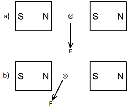
I have explained my assertion very well, but obviously some guys here pretend to be idiots. Especially the "expert" John Cuthber who wants only to confuse the readers by posting a diagram from my original post, thereby implying that something is wrong with it without saying a word, what that is. What were the other questions? 1) Ghideon asked me to give a reference that the force on the wire is a result of an interaction between the two magnetic fields: the one of the permanent magnet(s) and the other of the direct current-carrying wire. My answer is: No, I won't give a reference for something that is so obvious even to a 12-years old kid. 2) Studiot asked: What force is there if there is a wire but no current + the external field ? What force is there is there is a current but no wire + an external field ? The Fleming's left hand rule applies to the force which a stationary wire experience in an external magnetic field when a direct current begins to flow through it. So, what force could a stationary wire, through which no current flows, experience in a magnetic field? Should I answer to this? LOL! OK, I will answer it. NO FORCE. The second Studiot's question I didn't understand because it was not clear. Probably he thinks, let's say, on a cathode ray tube (CRT). Then my answer is: there is no difference in the direction of the force which a beam in a CRT and a current-carrying wire experience in an external magnetic field. For more detail, see my thread Cathode rays are not cathode rays!. My answer to the Beecee's last post: So much for your confidence in the ruling science. This time, great executive chief, I urge YOU to close this thread because I don't have the intention to lose my time with empty objections.
-
LOL! 1000 Australian dollars!!! It tells very well how sure you are in your "science"! I raise the bet to 10,000 American dollars. If you want more, I agree. About the procedure of payment and the other things, we well find the way how to do it.
-
What ....... evidence did you show? LOL. My stomach will burst!
-
Why don't you answer my question instead of analyzing my psychology? Would YOU bet? If you all are so sure in your "proper scientific methodology", then what is the problem?
-
I have experienced only hostility in this forum, nothing, but nothing else. And you tell me about my cantankerous attitude?!! Would YOU bet? You propose a grown-up bet. By the way, what should I answer to this question? "What force is there is there is a current but no wire + an external field ?" ???!!!!
-
I don't answer to questions which don't make any sense. Read your questions again and think a little.
-
Yes, my claims and explanations are in disagreement with current mainstream physics. You have asked for a reference that the force which a direct current-carrying wire experience in a magnetic field is a result of the interaction of two fields. I have already told you: I don't have to give a reference that 2+2=4. Look at the diagram below: In the figure (a) the wire is exactly in the middle between two magnets which create a magnetic field of uniform strength. In the moment when the wire is connected to a DC source, it makes a jerky movement downwards perpendicularly to the magnetic lines of force. In the figure (b) the wire is shifted somewhat to the left. In the moment when it is connected to a DC source, the wire makes a jerky movement to the left and down, that is, not perpendicularly to the magnetic lines of force. That is my claim and it is very easily verifiable. So, let us bet. If I am wrong, then I will go to live on a desert island for the rest of my life and will not say a word of physics anymore. If I am right, then you will have to go to the Swedish Royal Academy of Sciences and tell the highest authorities there that there is a man in North Macedonia who deserves a Nobel Prize (you are from Sweden, aren't you?). Do we have a deal?