
Mitko Gorgiev
Senior Members
-
Joined
-
Last visited
Everything posted by Mitko Gorgiev
-
I can have "Ground" without the Earth. The metal body which I speak of in my last reply can levitate in the space.
-
Connect one probe of a voltmeter to a phase wire (220-240 V). Connect the other probe to a not very large metal body that is completely insulated from the ground. The voltmeter shows, let's say, 10-20 V. Increase the volume of the metal body. As you increase it, the voltage rises. When the metal body is pretty large, the instrument shows 220-240 V. The further increase of the metal body's volume doesn't affect the number of volts. I can stick a piece of copper wire of 1 meter into the Earth and between it and a phase wire connect a voltmeter. It will show zero volts. Then what the heck of reference point is the ground?
-
Not at all. This is an upgrade of the previous thread. The main point is that electricity flows in an open "circuit". The "circuit" is never completed through ground as the contemporary physics and EE claims in the case when a phase wire is connected to a grounding wire. It is a pure nonsense. I can make a small LED (which needs 2-3 Volts to shine) to light up on 220-240V. Take a 5 mm green LED (according to my experience it needs the least amount of current to light up) and connect one terminal to the phase wire (it doesn't matter which, the positive or the negative). Connect a small piece of wire to the other terminal (the other end of the wire is free). The LED shines. Another nonsense is that when I touch the back end of the phase tester, it is said that it has to do with capacitance. Pure nonsense! My body is not a dielectric, but a conductor. Try also this: connect the biggest capacitor that you can find to the back end of the phase tester with only one terminal; the other terminal is free. Not the weakest shine you get.
-
A considerable amount of current can flow in an open circuit under certain conditions. I will present you a very simple experiment which undoubtedly proves that. But before that, let me give you a little introduction. Electricity is a fluid. Just as the water and the air can flow through pipes, so the electricity can flow through metal wires or other electrically conductive things. However, water and air are material fluids, whereas electricity is an immaterial fluid. Water is dense, air is less dense than water and the electricity is the least dense, actually it crosses the border of materiality and goes in immateriality. I will give you further down an example on this. Let’s first consider something else. When a body moves through space filled with air, then higher pressure is created in front of it, while lower pressure (depressure) behind it. The higher pressure is Plus, the lower pressure is Minus. I use to call this a ‘principle of an arrow’ (− >—> +). The greater the velocity of the body is, the stronger is the plus in front of it as well as the minus behind it. In this example a body is moving linearly through the air. Can we achieve higher and lower pressure on opposite sides of a body whose place in the space remains stationary? Yes, we can do that by means of a fan. When a fan is turning, then it is blowing in front of it (higher pressure/plus), but it is suctioning behind it (lower pressure/minus). Let’s say we have a fan without internal drive. If this fan is standing on the way of the wind, then it is turning. We can simulate this by taking a small fan (like those in computers) and a hair dryer. We bring the turned-on hair dryer close to the fan. It starts to turn in one direction. If we bring a turned-on vacuum cleaner close to it, then it starts to turn in the contrary direction. But if we attach the fan to a wall and then bring the hair dryer or the vacuum cleaner close to it, the fan is not turning. The reason is that behind the fan there is no space filled with air where the flux can spread or from where it can suction. Exactly the same happens with the electric flux. For example, when we touch with a finger the end of the phase tester (one-contact neon test light) (the other end touches the phase), our body becomes, so to say, the "space filled with air", actually an object with sufficient electrical conductivity whereto the flux can spread, or wherefrom it can suction and consequently the lamp lights up. [ The phase tester is a series connection of a resistor and a small neon lamp. ] If the fan in the already described experiment is a little away from the wall, then it is turning slowly. The farther it is away from the wall, the faster it is turning, until it reaches the maximum speed. The farther removal has no influence on the turning speed. Let’s compare this to the phase tester (further abbreviated as "PT"). If we attach a small piece of metal wire on the back end of the PT, then the lamp lights up weakly (we hold the PT on its plastic part, hence our body in this case has no influence on the phenomena). The longer or the thicker the wire is (or both at the same time), the stronger the lamp is shining, until it reaches the maximum. The further increasing of the wire volume has no influence on the lamp’s brightness. However, it is not solely the volume of the wire that matters, but also its conductivity. If we have two equal wires, but made of different metals, the lamp will shine brighter with the wire of better conductivity. But this is also a bit misleading, because the metal bodies can be also wires and if we have two kinds of wires of equal volumes and of the same material, but the one kind is thick and short and the other kind long and thin, we will get a better result (that is, a stronger current) with the shorter and thicker ones because they have lower resistance. The conductive body behind the PT doesn’t have to be made of metal. It can be also an electrolyte. As we already know, the pure water is a bad electrical conductor. But as soon as we add acid, base or salt in the water, its electrical conductivity considerably improves. Therefore, we can increase the volume of the conductive body behind the PT by immersing the wire in a container of salty, alkaline or acidic water. The earth/ground is actually a huge container of such water. The minerals in the Earth make the water an electrolyte and thus a large and good conductive body. But it is so only when it is sufficiently moist. In summers with low rainfall, the earth is dry and it is a bad conductive body. For example, if we build a city in the Gobi desert (Gobi is the driest place on the planet Earth), we cannot use the earth as “ground”. We have to invent another ground. We can, for example, let a jumbo-jet make circles over the city and use its huge chassis as “ground”. We will connect all the grounding wires to it and thus get sky-earthing. Of course I am joking, but principally there is nothing wrong in this joke. I have made up this example and oxymoron to stress how little we understand the electricity. I have seen the term “ground return” many times, as if the electric circuit closes itself through the Earth. No, in most practical cases it is not true. The electric current actually ends blind in the earth. Instead of ending in the earth, it can also end in the sky, i.e., in the jumbo-jet. Let me now present the experiment which shows that the electricity flows in an open DC circuit. All we need is a battery, a small LED lamp and two large conductive objects on both ends of the LINE. Below is the schematic of the experiment: I have recorded also a video to show the experiment: The larger the metal objects, the better the result, i.e., the LED-lamp is shining brighter. But this can be somewhat misleading, because it is not the size of the object that matters, but the volume of the conductive material and its conductivity. In this video I have used a hollow metal object – a washing machine. The result would have been much better if I have had a metal object of the same size, yet not hollow, but solid. If you don’t have two large metal volumes available, then as one large metal volume you can use the protective earthing conductor from a socket. We can imagine the battery as many fans/propellers in series. If these propellers are placed in a vacuum, then nothing will happen because there is nothing in the space around them to be moved. As soon as we put air or water in the space, the motion begins. It is the same with the battery and electricity. When we connect enough conductive volume behind the battery’s fans and in front of them, then the negative terminal has ‘Wherefrom’ it can suction and the positive terminal has ‘Whereto’ it can blow that, what the other terminal has suctioned. The electricity flow, just as the water- and air flow, is a continuum and as such it needs continuity along both sides of the “propeller”. You will never really understand the electric current if you think of it as of separate moving particles. Think of this: when one talks about water-flow, he doesn’t talk about moving particles. When one talks about air-flow, then he doesn’t talk about moving particles. Why so? Because both are fluids. And a fluid is like gelatin. It sticks together and moves together as a continuum. Then, why would we think of electricity flow as of separate moving particles? In case we close the conductive path in a circle, then the blowing from the one side meets with the suctioning from the opposite side, thus intensifying the electric flux many, many times. Regarding the open-circuit flow, think also of the following examples from the history: many of you certainly know that we can make a simple radio receiver without using any external power source. It is called a crystal radio. The electromagnetic waves from the transmitter hit the antenna and induce electric current in it which then goes in the receiver’s apparatus. But this current would be very weak to actuate the headphones of the apparatus if behind it there is not sufficient conductive volume. What is used as a conductive volume in this case? The Earth, of course. The apparatus has to be well-earthed if one wants a satisfactory result, i.e., to listen to the broadcast of certain radio stations on the headphones. Consider also this: In the 19th century was in use a single-wire telegraph (so-called “Earth-return telegraph”) after the people realized that the second wire is superfluous and thus they can cut the costs on wires. It was a simple DC on-off Morse code system with a battery earthed on both the transmitter’s and the receiver’s side. It was actually an open-circuit system. Another thing. If we swing a glass- or a vinyl-plate like a hand-held fan, then we cause an alternating air-current, that is, we cause longitudinal waves in the air. If we swing it pretty fast, then we cause sound waves at the same time (which are also longitudinal waves). If we now rub the glass or the vinyl plate with a woolen cloth, then the plate is electrified and if swing it again, we cause besides the air- and the sound-waves also electromagnetic waves (in relation to this please see How can we get an intuitive visualization of the polarization of an electromagnetic wave? ). We say that there is an electric field around the electrified glass and vinyl. What is an electric field? Is it something material? Did Michael Faraday mean some moving or stationary particles around an electrified or a magnetized object when he introduced the term “field” two hundred years ago? Certainly not. Actually, the scientists of the first half of the 19th century spoke of electric current as of electric field through the wires. If the glass or the vinyl is not moving, then the field is also motionless. If the glass is moving, then the field is moving together with the glass. This moving field is an electric wind. This wind, of course, is immaterial, too. If we move the glass towards one end of a piece of metal wire, then this immaterial wind propagates through the wire to its other end (if the wire is good conductive, it could be many kilometers long). At the other end blowing takes place(+) . If we move the glass away from the wire, then at the other end suctioning takes place (–). With the minus electrified object (that is, the vinyl), the opposite happens. Here is the evidence. Please look at the circuits below: When we move the glass plate toward and away from the wires (they could be many, many meters long and their free ends very far away from the circuits), then the LED lamps light up alternately: the LED lamp in the upper circuit lights up upon moving toward, while the LED lamp in the lower circuit upon moving away. When we move the vinyl plate toward and away from the wires, then the opposite happens. The results can be summarized as follows: For better results we should double the number of transistors (figure below). In this case the amplification is greater and the experiment is much more easily performed (we make actually the so-called Darlington pair of transistors). This experiment shows again that the electricity flows in an open circuit. Actually, when we move an electrified object towards or away from a piece of wire, there is already an electric current in it. We need the transistor’s circuits only to ascertain that that current exists. In relation to this article, please read also these: What is "ground" in electricity? A new explanation of the electric current? P.S. My niece recently got shocked while she was sewing on an electrical machine. The voltage of the socket (220–240V) was somehow present in the metal plate below the needle. She got actually shocked because she was touching the metal plate with her hand and at the same time she has touched with bare foot a computer chassis under the table which was plugged in and thus grounded. I have held many times a bare phase wire with a bare hand, but standing on an insulated floor and not touching anything with the other hand. The current which is flowing in my body in this case is too weak to be felt, because my body is the last link in the conductive chain. But if I touch with the other hand a large metal object, even if it is insulated from the ground, then a strong shock is inevitable. In this case my body is not anymore the last link in the chain and therefore the electric flux through it is stronger. If this shock lasts two-three seconds, it can be fatal, because the current goes through the heart. I have recorded also another video which I consider even more interesting than the previous one:
-
“Ground” (GND) is such an enormously confusing term on the field of electricity, so that if one doesn’t go back to the basics, the confusion can become only worse. First, I want to say that the word “ground” is absolutely not well-chosen word for what it should represent in the field of electricity. Much more appropriate is the German word “Masse” (which means “mass”). To the word “mass” for a better understanding I would add electrically conductive mass. With this I don’t want to say that the confusion in the German literature is lesser, but only that this word is more luckily chosen one. Here I will compare the electric current through a metal wire with wind (through a pipe). If a fan without internal drive stands on the way of the wind, then the fan is turning. We can simulate this by taking a small fan (like those in computers) and a hair dryer. We bring the turned-on hair dryer close to the fan. It starts to turn in one direction. If we bring a turned-on vacuum cleaner close to it, then it starts to turn in the contrary direction. But if we attach the fan to a wall and then bring the hair dryer or the vacuum cleaner close to it, it will not turn. The reason is that behind the fan there is no space filled with air in which the flux can spread or from where it can suction. Exactly the same happens with the electric flux. When we touch with a finger the end of the phase tester (one-contact neon test light) (the other end touches the phase), our body is becoming the "air space", actually the mass with sufficient electrical conductivity whereto the flux can spread or wherefrom it can suction and consequently the lamp lights up. [ The phase tester is a series connection of a resistor and a small neon lamp. ] If the fan in the above-mentioned example is a little away from the wall, then it turns slowly. The farther it is away from the wall, the faster it turns, until it reaches the maximum speed. The further removal has no influence on the turning speed. Let’s compare this to the phase tester (PT). If we attach a small piece of metal wire on the back end of the PT, then the lamp lights up weakly (we hold the PT on its plastic part, hence our body in this case has no influence on the phenomena). The longer or the thicker the wire is (or both at the same time), the stronger the lamp shines, until it reaches the maximum. The further increasing of the wire volume has no influence on the lamp brightness. [We can do the same experiment with an incandescent bulb if we connect it to a larger mass.] These are the basics of the concept called “Mass”. From here we see that for the current to flow through a metal wire, no closed circuit is needed. I can cite books on electrical engineering where already on their first page it is said that for the current to flow, a closed electric circuit is needed. The so-called protective conductor (protective earthing – PE) or popularly called “grounding” (the wire with yellow and green color together in Europe) leads to a metal plate buried in moist ground near the transformer or elsewhere. The purpose of this conductor is mainly for electrical devices that have a metal housing (washing machines, cookers, refrigerators etc.) It is possible for a phase wire inside the device to come unhooked or the plastic insulation to be damaged and the wire to touch the metal housing. In that case, the whole housing becomes a phase, that is, potential danger. To avoid this, the protective conductor is attached to the housing. If the phase somehow comes in touch with the housing, then the protective conductor becomes a large mass for the phase’s potential, a strong current begins to flow to the ground, the fuse in the installation blows out and interrupts the current, thus removing the danger. In electronic circuits, the minus-rail of the battery is often called Ground (Masse in German). This is also very confusing, because ground/Masse is not a source of electrical potential, whereas the minus-pole of the battery it is. In the field of electronics much more appropriate would be the word “Reference point” or “Common”. The metal chassis of a car is unfortunately also called Ground. The car chassis is connected to the minus-pole of the car-battery and it serves as a returning path for the current to save on wires. Take for example the lamp in the trunk. From the battery’s plus-pole goes a wire to this lamp, then the current flows through the chassis back to the minus-pole of the battery. Thereby the current finds the shortest path through the chassis to that pole, i.e., the path of lowest resistance.
-
No, you won't see me in November in Stockholm. But I will tell you this: My work is more worth than all the others together which have received that physics prize. In 50-100 years, the students will learn that what you read above. You can count on that. P.S. If you don't have arguments against my assertions, then get lost from my threads. You just waste the server's memory.
-
Do you know what the greatest hoax in the history of science is? In my view, it is this picture: It is taken from the Pink Floyd’s album “The dark side of the moon”. The members of one of the greatest bands of all times have also fallen for this hoax, taking this drawing as an idol of worship on their legendary album. The same drawing can be found in billions of textbooks throughout the world. Why is this drawing a hoax? Because it has nothing, absolutely NOTHING to do with the truth. The phenomenon doesn’t look like that at all. Johann Wolfgang von Goethe has already given the right picture two hundred years ago: There are numerous flaws in the first drawing: 1) At the emerging surface of the prism there are practically no colors, only white light; 2) The colors don’t diverge, so to say, parallel to each other as shown in the first drawing, but they combine; 3) There is no green color near the emerging surface. It appears later as a result of the mixing between the yellow and the cyan. The wider the incident beam is, the farther the green color appears; 4) All the colors in the first drawing have equal width. There’s no such thing. The yellow is actually much wider than the red. The same applies to the violet and cyan. The width of the yellow is the same as the width of the violet. The width of the red is the same as the width of the cyan; 5) There is no separate orange color in the refracted beam; 6) There are also no seven colors in the so-called spectrum (as it is usually said). On the plus-side there are only yellow and red; on the minus-side there are only violet and cyan. Together with the green there are overall five colors. Another hoax in relation to the previous one is the following drawing: It appears in the textbooks when the so-called chromatic aberration is discussed. The true picture of the phenomenon looks like this: A collimated beam of light goes through a chromatic convex lens. It converges in a point and then diverges. Before the focal point the beam is rounded by a yellow-red wreath (figure a below) and by a violet-cyan wreath after the focal point (figure b). The yellow color turns into violet, the red color turns into cyan. Have you ever heard of the very simple experiment just mentioned? I doubt you have. Do you know why? Because the science of the last centuries tends to cheat. It sweeps under the carpet the experiments which are not in accordance with its fake theories. If it describes such experiments, then the contradictions become obvious. It should then admit that its theory is wrong and that it doesn’t have a true explanation of the phenomena. But this science would rather cheat than to admit its cluelessness about such simple experiments. The members of the academic community would lose their authority and also their reputation as the smartest people of the society. I CALL YOU TO REMEMBER THIS EXPERIMENT VERY WELL because it disproves several hoaxes of the contemporary science: 1) the light is not composed of colors; 2) there is no such thing as frequencies of colors; then, how on Earth would the frequencies suddenly change into other on their linear path of propagation in a point far from refraction surface?!! ; 3) there is also no such thing as wavelengths of colors; 4) light and colors are not electromagnetic waves. I want to elaborate something regarding the hoax below: Something similar to this can be obtained with a convex lens in a very specific way. Let me explain. Let’s say that on the incident surface of the lens we glue two opaque papers: an opaque ring on the outer edge of the lens and an opaque circle in the middle as presented in the figure (b) below: A collimated beam goes through the lens of the figure (b). If we hold a white sheet of paper before the focal point, then we will get the image presented in the figure (c). A YELLOW-red ring appears at the outer edge, while a VIOLET-cyan ring at the inner edge of the light ring. Between them it is white. Now, let us narrow the white ring of the figure (b) above, so that we get a lens like the one presented in the figure (b) below. In this case the yellow color from the outer edge will meet the cyan color from the inner edge resulting in a green ring in the middle (figure c). Only in this way we can get something similar to the hoax image. I believe that the images in the second to last series of figures could serve as a basis for explanation of the optical phenomenon Halo which appears in the very cold polar regions. In some photographs of Halo the yellow-red ring appears at the outer edge, while the violet-cyan ring at the inner edge: But in other photographs it is reversed: just like the figure (c) and (d) in the mentioned series of figures. Maybe the frozen water drops in the atmosphere make somehow a huge lens. Part 2 An explanation of the extraordinary experiments presented in the video below: This video exposes very obviously the whole emptiness of the Newton’s theory of colors. Please watch it carefully (especially its later part) before reading this post. The key for an explanation of the prismatic colors and the extraordinary experiments presented in this video is the “principle of the arrow”. I call you to remember this phrase very well because it will certainly be the milestone of the future science. What is the principle of the arrow? Although I have elaborated it many times in my older answers and posts, still I will repeat the main points here for those who haven’t read them (I will also cite some articles of mine at the end of this post). When a body moves through space filled with air, then higher pressure is created in front of it, while lower pressure behind it. The higher pressure is Plus, the lower pressure is Minus. I use to call it the ‘principle of the arrow’ (− >—> +). The greater the velocity of the body is, the stronger is the plus in front of it as well as the minus behind it. And look now: this very principle can be found wherever the light produces colors. The archetype of this pattern is the flame of a candle or a cigarette lighter. A violet/cyan minus appears at the back and a yellow/red plus at the front of this fiery arrow: The left picture is a real photograph of an opalite stone illuminated from below with a white LED lamp. ( Opalites are very cheap stones and easy to find. I urge everyone who is really interested in light and colors to find these stones. ) Let’s find the same principle in the phenomenon of refraction colors, that is, the colors which appear on a triangular prism. The light undergoes two refractions on the prism: one on entering the prism and another on emerging from it. For the birth of the refraction colors there is no need of a double, but only of a single refraction. In the following video it is visible how the colors appear only with one refraction (from 0:48 to 0:57): Let me jump for a moment to something else, to the question of the so-called Bernoulli’s principle (footnote 1). Please look at the picture below: The water flows through a wider pipe and then through a narrower pipe. The velocity of the water increases in the narrower pipe. As a result, the water column over it is lower than over the wider pipe. Why is that so? The water columns over the pipes could be imagined as many tails of the water-body. Since the velocity of the water is greater in the narrower pipe, a stronger MINUS occurs in its tail than in the tail of the wider pipe, thus the air-pressure from above lowers the water column over the narrower pipe more. At the same time a stronger PLUS arises at the front part of the narrower pipe. Everyone knows that the water-jet which comes out of a pipe reaches farther if we narrow the pipe. That happens because higher pressure occurs in the front part. So, HIGHER PRESSURE within the plus-side of the water-body, while LOWER PRESSURE within its minus-side. But could the water-body with the higher pressure in its plus-side and the lower-pressure in its minus-side exist without a material environment, that is, without the surrounding air? No, it could not. The surrounding air is an inevitable actor in the whole story. I want here to stress that in the case of the moving solid body, the higher and the lower pressure arise in the surrounding air, while in the case of the moving liquid body, they arise within it. Let us get back to the light. When the light propagates through the void space, then there is nothing around it to strike its body in, so it propagates freely. But when there is more or less transparent matter on its way of propagation, then it experiences resistance, so that higher light-pressure arises in the front of its body, while lower light-pressure in the back. The higher light-pressure manifests itself as yellow-red, the lower pressure as violet-cyan. When a beam of light propagates through space, its frontal surface is at right angle to the direction of propagation. We can call it a frontal propagation of light. But when the beam is refracted, then it propagates sideways, meaning that its frontal surface is no longer perpendicular to the direction of propagation. We can call it a sideways propagation of light. These two ways of propagation can be imagined as follows: imagine two threads stretched across a room, one horizontally, the other diagonally. On each of the threads is hanging a pierced sheet of paper. We are moving the two sheets along the threads so that they are always in a vertical position. In the figure (a) below is represented the frontal propagation, while in the figure (b) the sideways propagation. The sheet in the figure (b) does not have to be necessarily vertical. It only must not be at right angle to the direction of the thread. Please look at the diagram below: A beam of light is refracted. After the refraction, besides the normal component, the beam gets an additional component in the direction marked with the black arrows. Higher light-pressure arises at the front of this component (i.e. plus-colors), while lower light-pressure (i.e. minus-colors) at its back. But these different light-pressures can occur due to the surrounding air, similarly to the cases of the solid and the liquid body. In other words, if we place a prism or a diffraction grating in a very high vacuum, then I claim that the refracted or diffracted white light will remain white after passing through them. Now, please look at this screenshot from the video: A beam of light has passed through the prism, but the colored boundaries are covered with black papers. Let’s say that the source of light and the prism are placed in a black box and you see only the beam presented in the screenshot. Then someone asks you: He: What do you see? You: A beam of white light. He: Is it a normal light? You: What kind of question is that? Of course it is a normal white light! He: No, it is not a normal light. Watch now! And then he places an object in the middle of the beam (screenshot below). He: Does a normal light throw a shadow like this?! You: No, it doesn’t … then, what kind of light is this? He: It’s not a normal, but a slanted light. Let us now move to the experiments when only one colored ray of the so-called Goethe’s spectrum passes through a narrow slit (screenshot below): There are actually three cases: 1) the cyan ray passes through the slit; after that we see a green ray and a blue ray bound together; 2) the magenta ray (the author of the video calls it purple; Goethe called it also purple) passes through the slit; after that we see a red ray and a blue ray separated from each other; 3) the yellow ray passes through the slit; after that we see a green ray and a blue ray bound together. In the screenshot above only the second case is presented for the sake of shortness. The magenta arrow is added by me to stress that is, the ray has still its own color in the close vicinity of the slit. The same applies for the cyan ray and the yellow ray when they exit the slit. Before I explain what is going on here, let me tell you something else. Please look at the figure below: The magnetic field of the magnet is weaker at a greater distance from the magnet’s pole (figure a). At a greater distance than d, we could say that the strength of the magnetic field is practically zero. The weakening of the strength is symbolically represented by the different shades of gray. The weakening is also symbolically represented by the red and the blue triangle in the figure (b). If the two identical magnets are brought at the distance ‘d’ (or less than ‘d’) without allowing them to come together, then in the interspace between them there is a uniform magnetic field because the two fields complement each other. This means that the strength of the magnetic field is the same in every point of the interspace (figure c). The magnetic field is uniform in terms of strength, but it is not homogeneous in terms of polarity. The Plus and the Minus retain their character just as before the bringing of the magnets close to each other. Something similar to the things just discussed we have with light. Look please at the screenshot below: The light above the plate’s shadow and the light below it can be imagined as two separate beams of light. Since these beams are far from each other, there is no interaction between them. It corresponds in a way to the two magnets which are far from each other. Look now at this screenshot: The shadow is now narrow so that an interaction between the beams can occur. The Plus from below meets the Minus from above, that is, the red color meets the blue-violet. Their overlapping bears magenta. This is not the same case as when we mix chemical colors. If we mix acrylic red and acrylic blue-violet, we do get magenta, but we cannot bring the process back, that is, we cannot separate it into two colors. With the light it is possible. On the right of the last image, the corresponding situation with two magnets is presented. When the magnets are close to each other, then their fields interact, but, as I said before, the Plus and the Minus retain their character. In relation to this, please read (link at the end of this passage) about another hoax of the contemporary science, the so-called Fleming’s left hand rule. This rule states that if a current-carrying conductor is placed in a uniform magnetic field, then it will experience a force which is perpendicular to the magnetic lines of force. This is true only in the case when the conductor is placed exactly in the middle between the magnets, where the strength of the Plus and the Minus are equal. In every other case it is not true that the force acts perpendicularly to the magnetic lines of force. (see these articles Is the Fleming’s left hand rule valid? The plane which is exactly between the magnets corresponds in a sense to the magenta color of the Goethe’s spectrum. Now, let’s get back to this screenshot: What is actually going on here? The magenta ray enters an environment of low light-pressure, i.e. the pressure around the ray suddenly drops. Therefore, it is a suitable environment for it to dissolve in the original Plus and Minus components. Please note a very interesting detail in this process. Before the slit in the last screenshot, the magenta ray comes about through mixing of the red ray from below with the blue-violet from above. After the slit the ray splits into a red ray above, while the blue-violet one is below, that is, the rays have exchanged the places. What does this tell? It tells that this ray behaves as the original refracted light (marked with the added three-colored arrow) although it is born from rays of reverse order. But we can say also otherwise: the red and the blue-violet ray retain their own directions just as if they were not mixed before the slit. Look now at this screenshot: In this case the magenta ray doesn’t split into two. Why? Because it enters an environment of high light-pressure. The forces around it are so strong that it cannot fall apart. I leave the other variations of the experiments to the reader to try to explain them on his/her own. Here are some important articles of mine related to this post: Why is the sky blue? How does light make colors appear? Is the designation "positive" and "negative" in electricity arbitrary? P.S. The author of the video succeeded to split also the green ray in its constituent parts, yellow and cyan, but it is not presented in the video. It is presented on his website. Here is the link where you can find this photo: Inverted spectra of monochromatic rays
-
As I said, I don't have the intention to reply to people who pretend to be idiots. I am done.
-
I have explained my assertion very well, but obviously some guys here pretend to be idiots. Especially the "expert" John Cuthber who wants only to confuse the readers by posting a diagram from my original post, thereby implying that something is wrong with it without saying a word, what that is. What were the other questions? 1) Ghideon asked me to give a reference that the force on the wire is a result of an interaction between the two magnetic fields: the one of the permanent magnet(s) and the other of the direct current-carrying wire. My answer is: No, I won't give a reference for something that is so obvious even to a 12-years old kid. 2) Studiot asked: What force is there if there is a wire but no current + the external field ? What force is there is there is a current but no wire + an external field ? The Fleming's left hand rule applies to the force which a stationary wire experience in an external magnetic field when a direct current begins to flow through it. So, what force could a stationary wire, through which no current flows, experience in a magnetic field? Should I answer to this? LOL! OK, I will answer it. NO FORCE. The second Studiot's question I didn't understand because it was not clear. Probably he thinks, let's say, on a cathode ray tube (CRT). Then my answer is: there is no difference in the direction of the force which a beam in a CRT and a current-carrying wire experience in an external magnetic field. For more detail, see my thread Cathode rays are not cathode rays!. My answer to the Beecee's last post: So much for your confidence in the ruling science. This time, great executive chief, I urge YOU to close this thread because I don't have the intention to lose my time with empty objections.
-
LOL! 1000 Australian dollars!!! It tells very well how sure you are in your "science"! I raise the bet to 10,000 American dollars. If you want more, I agree. About the procedure of payment and the other things, we well find the way how to do it.
-
What ....... evidence did you show? LOL. My stomach will burst!
-
Why don't you answer my question instead of analyzing my psychology? Would YOU bet? If you all are so sure in your "proper scientific methodology", then what is the problem?
-
I have experienced only hostility in this forum, nothing, but nothing else. And you tell me about my cantankerous attitude?!! Would YOU bet? You propose a grown-up bet. By the way, what should I answer to this question? "What force is there is there is a current but no wire + an external field ?" ???!!!!
-
I don't answer to questions which don't make any sense. Read your questions again and think a little.
-
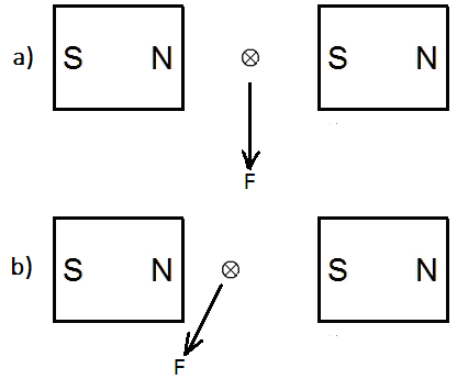
Yes, my claims and explanations are in disagreement with current mainstream physics. You have asked for a reference that the force which a direct current-carrying wire experience in a magnetic field is a result of the interaction of two fields. I have already told you: I don't have to give a reference that 2+2=4. Look at the diagram below: In the figure (a) the wire is exactly in the middle between two magnets which create a magnetic field of uniform strength. In the moment when the wire is connected to a DC source, it makes a jerky movement downwards perpendicularly to the magnetic lines of force. In the figure (b) the wire is shifted somewhat to the left. In the moment when it is connected to a DC source, the wire makes a jerky movement to the left and down, that is, not perpendicularly to the magnetic lines of force. That is my claim and it is very easily verifiable. So, let us bet. If I am wrong, then I will go to live on a desert island for the rest of my life and will not say a word of physics anymore. If I am right, then you will have to go to the Swedish Royal Academy of Sciences and tell the highest authorities there that there is a man in North Macedonia who deserves a Nobel Prize (you are from Sweden, aren't you?). Do we have a deal?
-
This article on how the light produces the colors I will begin with phenomena that everyone can see in daily life. If we look at the flame of a candle or a cigarette lighter in a dimly lit room, the flame is blue-violet in the lower part and yellow-orange in the upper part. If the part of the wick running over the wax is very short, then the flame is very small and it appears only blue. The flame of a gas stove is also blue, but as soon as we increase the gas supply, yellow tongues appear in the upper part of the flame. The smoke of a cigarette, whose smoke columns are not very dense, appears blue against a dark background, whereas yellow-orange against a light background (for example a window in daylight). When the sun rises or sets, the sky around it is yellow-orange or even red. This color is also projected onto the opposite horizon or onto the clouds at various points in the sky, while the upper part of the sky retains its blue color. If we look closely at the sunset horizon, we can sometimes also notice that a greenish part appears between the lower yellow-red and the upper blue part. During larger volcanic eruptions, when the air currents spread the smoke towards the sun, it was noted that the sky turned orange-red (such a case has been described during an eruption of Krakatau). The cloudless day sky appears blue. The higher we look the deeper blue it gets, especially on clear days by low air humidity. The lower we look, the brighter the blue of the sky, even turning into whitish. Mountaineers climbing mountains of thousands of meters tell us that the sky’s color is the deeper blue the higher they get. The mountains very often appear blue, darker blue the nearer, lighter blue the more distant ones. Dirty windows appear orange-yellow. If we apply a thin layer of sour milk to a clean glass surface and look through it toward a window with daylight, the surface appears yellow-orange. The same surface against a dark background appears faintly blue. This phenomenon can be observed much more intensively on opalite stones, which can be found in jewelry stores. The opalite is a mineral, a sort of glass with certain additives. When we look through this stone toward a light source, it appears yellow, orange or red, depending on the concentration of additives in it (we need several stones with various concentrations to see this). If there are no additives in the opalite, it is transparent and colorless. At low concentration the stone turns yellow, with the increase it turns orange, to change to red and become almost opaque at very high concentration. The same stone against dark background appears violet at low concentration, blue at greater, to turn to bright blue (i.e. cyan) and then to whitish at very high concentration. If a small white LED lamp is neared the stone in the darkened room, then the yellow (orange or red) color is projected onto the opposite wall, while the stone itself is violet (blue, cyan or white). If a longish stone with moderate and uniform concentration of additives is illuminated with a white directional LED lamp along its long axis, then it gives the following picture: If a longish stone with a quick uniform increase of the concentration of additives along the long axis is illuminated with a white directional LED lamp along that axis from the side with the lower concentration, then it gives the following picture: This is a real photograph of such an opalite stone (illuminated from right): All the aforementioned phenomena and experiments, but also others whose description will follow, come down to a single principle, that of plus and minus. In this particular case we can call it “the principle of the arrow”. What is the principle of the arrow? When a body moves through space filled with air, then higher pressure is created in front of it, while lower pressure behind it. The higher pressure is Plus, the lower pressure is Minus. I use to call it the ‘principle of the arrow’ (− >—> +). The greater the velocity of the body is, the stronger is the plus in front of it as well as the minus behind it. And look now: this very principle can be found wherever the light produces colors. In the flame of the candle and that of the lighter we have the archetype of this arrow pattern. In the front of this ‘fiery arrow’ appears the plus color (yellow), in the back the minus color (blue-violet). As we will see later, the yellow and the violet are the two fundamental plus/minus colors of the world. The red (including the orange) is nothing else but weakening of the yellow; the cyan (including the blue) is nothing other than weakening of the violet. When the strong plus (yellow) meets the weakened minus (cyan), their overlapping bears the green. In this color dominates of course the plus, which can be seen, among other things, on the leaves of the trees. In autumn they turn from green to yellow, then to orange, and even to red on some trees, but never to cyan, blue or violet. If the strong minus (the violet) overlaps with the weakened plus (the red), this gives birth to magenta. From the mixing of the strong plus (the yellow) and strong minus (the violet) we get nothing, that is, we get their cancellation, which means more or less dark gray. When we observed the small opalite stone with moderate concentration of additives against a dark background, it appeared blue. What does it actually mean, to observe the stone against a dark background? It means that we are positioned sideways to the stone (considering the direction of the light), seeing the ‘tail’ of the light permeating through it. Therefore the stone appeared with a minus color. Since it is small and with moderate concentration of additives, it cannot hold up the light, that is, the light passes through it and makes a bright yellow spot on the opposite wall (of course, we couldn’t see that by diffused daylight, but we have perceived it with the help of the directional white light of the LED lamp. To see the yellow color by daylight, we hold the stone close to the eye looking through it in the direction where the light comes from). But when the stone was longish with moderate and uniform concentration of additives, then, illuminated along the longitudinal axis, it absorbs i.e. withholds the light to a great degree, thus the yellow and the red color project already in it on its far side. Therefore it gives the image of a candle or a lighter. When the concentration increases rapidly along the longitudinal axis, then the cyan catches up the yellow, thus the green color appears here as well. From what has been said so far, we can conclude that the colors are born when the light encounters matter as an obstacle on its way of propagation; or, in other words, when it comes to friction between the light and the matter. For the eye which looks toward the light source, the light is white when there is no or little matter between the eye and the source, that is, when there is no or just a little friction. As the concentration of matter increases, so the light becomes yellow, then orange, then red; at the end, at very high concentration, the light is completely attenuated and it turns black. In order to increase the resistance it is not always necessary to increase the concentration of the matter, but the thickness of the material layer (through which the light passes) can be increased as well. When the sun is rising or setting, the thickness of the atmosphere layer is the largest, which is why the light is red. The upper part of the sky (i.e. the atmosphere) is blue because in relation to this part we are positioned sideways and see the rear of the light permeating the atmosphere. As the sun rises further, so the thickness of the material layer through which we directly see the sunlight diminishes, thus the light becomes orange, then yellow, to finally become to a great degree white, because the thickness of the layer, that is, the resistance is small and insufficient to color the light considerably. However, the rest of the sky is blue for the same reason we have already stated. When we observe a small opalite stone with low and uniform concentration of additives sideways, it is blue-violet, with greater concentration blue and even greater light blue (i.e. cyan), and then turns into whitish. As the concentration increases, the light can permeate the stone ever less, thus the permeation gradually transitions into reflection of the light from the additives; and the white light, when reflected, remains white. For the same reason the part of the sky in the zenith is blue-violet (the thinnest layer to the dark, immaterial universe, especially at higher altitudes), the lower part is light blue, to end in whitish on the horizon. For the same reason we see often the near mountains blue-violet (especially if they are dark, that is, forested), the farther ones blue, and the very distant whitish. This largely depends on the current degree of the air humidity. The more transparent the air is (i.e. with less vapor), the darker blue the near mountains are (this does not apply, of course, to the very close ones). Hence, the gradations when we see the plus-side and the minus-side of the light, starting from low concentration of matter and going to higher, or starting from a thin, going to a thicker material layer by unchanging concentration, are the following: White → yellow → orange → red → black (plus-side) Black → blue-violet → blue → cyan → white (minus-side) The images below show a kind of spiral, which we will call a double plane spiral. ‘Double’ because there are two spirals that intertwine. But which spirals are we talking about, the white or the black? The question makes no sense, because the one cannot exist without the other. If we place the first spiral on a spinning top and turn it to the left, then it will expand (the circles will move outwards), that is, it will push us (+). If we observe carefully what is happening when the spiral is turning, we will notice that thin red strips appear along the outer edges of the white circles as long as the spiral is spinning fast, and as the spinning slows down, the strips turn into yellow (the experiment should be carried out near a window through which daylight comes in, but not directly from the sun). Along the inner edges of the white circles appear thin light blue strips as long as the spiral is turning fast, and as the speed decreases, the strips turn into blue-violet. If we turn the spiral to the right, then the circles are moving inwards (−), so that now the red or the yellow strips are visible at the inner edges of the white circles and the light-blue or the blue-violet strips at the outer edges. Regarding the second spiral (on the right), it happens the same: when the circles are moving outwards, the red and the yellow strips appear on the outer edges of the white circles, and when they are moving inwards, these colors appear on their inner edges. We see that here recurs the same pattern as in the previous phenomena: the yellow or the red color appear on the front and the blue-violet or the light blue on the rear side. For, when the circles are moving outwards (we say circles because the white and black spirals appear as circles as the top spins), then the outer edges of the white circles are the front and the inner edges are the rear of the light. Since the light is reflected only by the white circles, we can imagine light and dark tubes, or, let’s say toroids above the spiral. These toroids are static when the spiral stands still, however, they move outwards or inwards when it spins. To clarify what follows, we will make a comparison with a tennis ball bouncing off a horizontal surface at an acute angle. Thereby the angle of reflection is equal to the angle of incidence. However, this applies only when the surface is still. If it moves in the same direction as the projection of the ball’s trajectory onto the surface, then the ball receives an additional movement, thus the angle of reflection is no longer equal to the angle of incidence, but greater. [Do you remember the video game “Pong”?] Something similar can be assumed with light. When it is reflected by the white circles which move let’s say outwards, the light gets additional movement towards the dark parts, in other words, it penetrates sideways into the matter, i.e., into the air over the dark circles which are in front of it. The sideways penetration means more intense friction than the frontal penetration, so this friction will produce plus colors on the front (that is, on the outer edges of the white circles) and minus colors on the rear side of the light (that is, on the inner edges of the white circles). During faster turning of the disk, the white circles move faster, the reflection angle is greater and therefore the friction intensity too, hence red color on the front and blue on the rear. As the rotation slows down, so the red turns into yellow and the blue into violet due to the diminishing of the reflection angle and therefore the intensity of the friction, too. It should be kept in mind that we deal here with diffuse light. This is mentioned for the reason that the direct light in some parts of the disk would receive additional motion, but in other parts retardation. From the aforesaid the reader can conclude on his/her own, how we would explain the appearance of colors on Benham's disk when it is turning. Let us consider the following simple experiment. We take a sheet of paper and hold it about 15-20 cm in front of one eye (the other eye is closed) opposite to an uncurtained window through which daylight comes in. If we observe the edge of the sheet carefully, we will notice a thin yellow strip along the edge. We can also pierce with a needle a small hole in the sheet and look through it towards the window. Then we will notice yellow circle along the edge of the hole. If we now move the sheet in front of our eye so that its edge and the dark edge of the window, which of course is farther away, form a narrow gap, then we will notice that a blue strip appears at the farther edge. If this arrangement is fixed and the gap is quite narrow, then green emerges in the middle between the plus- and minus-colors. Now we go over to experiments with a triangular glass prism (hereinafter: prism). The experiments that will be carried out we can divide into subjective and objective ones. Subjective experiments are called those when we hold the prism in front of our eyes and look through it, and objective ones are called those when we let directed light pass through the prism and then, at a greater or lesser distance behind the prism, the path of the light is blocked with a white wall which may also be a white sheet of paper that we hold behind the prism. The prisms are usually made equilateral with three equal angles of 60°. One of them, in this case no matter which, is called the (refractive) angle of the prism (also called apex angle). It can be directed upwards (▲) or downwards (▼). In essence, there is no difference between the two possibilities. We will choose the second variant as more practical. Therefore, unless explicitly stated otherwise, the variant of refractive angle being directed downwards is assumed. If we hold the prism horizontally in front of our eyes and see through it the objects around us, we notice that they take on additional impressive colors. On closer inspection, we perceive that these colors appear where abrupt horizontal or oblique dividing lines (boundaries) between lighter and darker surfaces can be seen, whereas on the monochrome surfaces and on those with gradual transition from light to dark as well as on vertical abrupt ones, it is not the case. In the last variant, however, we will notice additional colors if we hold the prism obliquely or vertically in front of our eyes. The additional colors are paler if the transitions are milder, i.e., when the boundary contrast is weaker, and they are stronger when the transition is abrupt. They are actually the strongest on boundaries where the contrast is maximal, that is, between deep black and bright white. Therefore, we will begin our experiments with detailed observations of boundaries between black and white areas. We can do it by preparing white papers with black areas on them, or vice versa; or we can attach on a window, through which daylight comes in, opaque cardboards into which certain shapes are cut. The attached cardboard represents a black area, and where there is none, it is a white area. If we attach a cardboard in the shape of the image below (left) and the rectangle is wide (it is meant the smaller side), and if we look at this shape through the prism from a few steps away, then we see the image in the middle. А yellow-red strip appears at the upper formerly black-white boundary and a violet-cyan one at the lower boundary. If we turn the prism so that the refractive angle is upwards, then we see exactly the same image, only turned 180°. We notice that in the yellow-red strip the yellow stripe is noticeably wider than the red one, and in the violet-cyan strip the violet stripe is noticeably wider than the cyan one. If we approach the rectangle without losing sight of it through the prism, the yellow-red and the violet-cyan strip become ever narrower, and as we get very close, they practically disappear. If we move away from the rectangle, then the colored strips spread. As they spread, so the yellow and the cyan stripe begin to approach each other, the white space between them is getting narrower, and at the moment when the two colors touch, a green color appears. As we move farther away, so the cyan disappears, more precisely, it is completely covered by the yellow and converted into green, so now we see four colors: red, yellow, green and violet (the right image above). As we move even farther, a dark field begins to appear between the green and the violet, and even farther, between the red and the green. The gap between the green and the violet can be clearly seen when we observe through the prism a distant, not very bright white street light. If we think about where we actually see the image through the prism, we realize that it is shifted and that we see it significantly below its true position when the refractive angle is turned downwards, and significantly above its true position when the angle is turned upwards (the eye always projects the image in a straight line; for example, when we see an image in a mirror at an acute angle, then we see it as if it were behind the mirror. Moreover, when we look through a window the image is also shifted, except in the case when we look through it at right angle.). We see the colored rectangle also a bit curved, namely, curved upwards in the first case (▼), and curved downwards in the second (▲) (here again we get a kind of arrow shape with the plus-colors at the front and the minus-colors at the back) . This is because when we look through the prism, we see both in straight and oblique direction at the same time. In the straight direction there is smaller thickness of the prism in front of our eyes, in the oblique direction larger thickness (figure below). With larger thickness of the prism, the image is shifted more. This curvature does not appear in objective experiments when the sunlight falls on the prism, but it can be seen when the light source is a small white LED lamp that we hold close to the prism. The reason is that the sun is a broad and distant source, thus its rays can be regarded as parallel, whereas the LED lamp is a small and near source and therefore to it the same applies as to our eyes. If we observe the same image through a prism with a smaller refractive angle, say 15°, the only difference is that the image is shifted less and the width of the colored strips is smaller, of course at unchanged distance of the observer from the image. In order to get the same width of the strips with this prism as with the equilateral one, we have to move farther away from the window. If we look at the image through prisms with equal refractive angles, from the same distance, but made of different types of glass, let's say from flint glass, crown glass and acrylic glass, then here again we will notice differences in the displacement of the image and the width of the colored strips. With the flint-glass prism the image is mostly shifted and the thickest strips can be seen, because the flint-glass has the largest refractive index of these three types of glass, that is, the light is mostly refracted by it. Now on the window we attach two square cardboards, horizontally placed, one above, the other below, which touch each other only with their vertices (left image below). When we look at this image through the prism we will see the image on the right. We have brought the yellow-red and violet-cyan strips on the same line. We notice that there is equality in width of both groups as wholes, but also separately: the width of the yellow stripe is the same as that of the violet, and the width of the red stripe is the same as that of the cyan. What is also very important here is that the red stripe appears at the expense of the black field, while the yellow one at the expense of the white field. In other words, a part of the black field has turned into red and a part of the white field has turned into yellow. Consequently, on the other side a part of the black field has turned into violet, and a part of the white field into cyan. Where previously was the boundary between the white and the black, now that line is the border between the yellow and the red, i.e. between the violet and the cyan. Let's move on to observing a circle. For that purpose we cut a circle in a cardboard and attach it to the window (left image below). When we look at it through the prism we see the image on the right. The circle has taken on an elliptical shape with the well-known yellow-red belt above, and the violet-cyan one below. They are widest at the top and the bottom edge and become narrower to the left and the right side, to completely disappear at the extreme left and right points. If we fix a small circular cardboard in the center of the circle, in other words, if we place a central point in it, and although this small circle observed through the prism becomes colored and therefore not clearly visible, we can still notice that it appears in the upper part of the ellipse. Instead of observing white rectangles and circles on a black background, we can do the opposite - observe black rectangles and circles on a white background. For this purpose, we attach on the window an opaque cardboard, once in a shape of rectangle, another time in a shape of circle. We will get the images below. In this case, if we cut the rectangle or the circle smaller or if we move away from the window, then the violet and red color will approach each other and at the moment of their overlapping, a magenta color is born. In the first case the wider yellow(+) and the narrower cyan(–) overlap to produce green. This time the wider violet(–) and the narrower red(+) overlap producing magenta. In the case of the black rectangle, it is as if we had two light sources, one up and one down (the rectangle can be imagined very long). The “head” of the lower light with the plus-colors manages to catch up with the “tail” of the upper light with the minus-colors and their overlapping gives birth to magenta. If on a white sheet of paper we draw horizontal narrow black stripes so that they are of same width to each other, but also to the white space between them (i.e. to the white stripes) and if we look at this image through the prism from a certain distance, then only two colors remain in the image: the green and the magenta. In other words, instead of black and white, we now see magenta and green stripes. In the white stripes the yellow has merged with the cyan becoming green, in the black stripes the violet has merged with the red becoming magenta (white stripe → green; black stripe → magenta). Instead of fixing cardboards on the window, we can carry these experiments out in such a way that we observe the mentioned shapes as black and white areas on paper. We will see through the prism exactly the same images as before. But in this case we can make the black and white areas in different shades of gray, from black to white. We will notice that absolutely nothing changes in the results, except that the colors get paler the less the contrast is between the darker and the brighter shades of the gray areas. In order to accomplish this grading on the window, we need papers with different transparency. This can be achieved by using tracing paper in different number of layers. The simplest objective experiment we can make with the prism is the following: in a room in which direct sunlight enters we hold with one hand the prism with the refractive angle downwards, of course in the field of the direct light, and with the other hand behind the prism we hold a white sheet of paper. If we hold the sheet very close to the prism, then we will see only a regular bright rectangle without any colors. As we move the sheet away from the prism backwards and upwards at once, then a violet-cyan strip appears on the upper edge of the rectangle, and a yellow-red strip on the bottom edge. With the further withdrawal of the sheet, the strips widen, the middle white field of the rectangle narrows, and in the moment when the yellow and cyan stripe overlap, green appears. Now we have a continuous colored spectrum. All that has been described so far for the subjective experiments with the prism fully recurs in the objective experiments; therefore we don’t feel it is necessary to repeat it again. We will only describe the way these experiments are carried out. On the incident or emerging surface of the prism we stick an opaque paper and once we cut a rectangle, another time a circle in it. Then we hold the prism in the sunlight as we did in the previous experiment. This corresponds to the observing of the rectangle and the circle in the subjective experiments. Moving the sheet of paper behind the prism corresponds to the changing of our distance from the window with the attached cardboards. Another time on the prism we stick two opaque squares that touch each other with the vertices. In order to get a magenta color we stick only an opaque strip horizontally in the middle of the prism. To carry out the experiments with darker or brighter gray surfaces, we need to stick on the prism more or less transparent papers. Glass prisms that can be purchased have not large incident surface, so that no significant amount of sunlight can fall on them. By covering it partly with opaque papers we reduce the amount of light further. Therefore, the colored phenomena at a not large distance behind the prism already weaken. Glass prisms with bigger surface would be quite heavy. Johann Wolfgang Goethe for this purpose used a water prism in his experiments. It was a prism-shaped ‘aquarium’ fixed in a wooden construction with the refractive angle directed of course downwards. The prism had a large incident surface so that the phenomena at longer distances didn’t weaken significantly. Its drawback was that after every experimenting the water had to be exhausted because the lime would have blurred the glass. What we have said earlier, that there is no difference between the subjective and the objective experiments, is not entirely true. There is still one small and baffling difference. When we observed a white field on a black background through the prism (▼) in a subjective experiment the plus-colors were up, the minus-colors down, whereas in an objective experiment the colors are placed reversed. The colors obtained with the help of the prism are called refractive colors, because the Latin term “refraction” refers to the change of direction of light when it falls at an acute angle on its way from one medium to another which have different densities. The refraction is always inclined to the denser medium, that is, the made “curve” encompasses larger part of the denser medium (figure below). We can compare the change in the direction of light with a vehicle passing over at considerable speed at an acute angle from solid asphalt into soft muddy ground or vice versa. The vehicle then inevitably changes the direction of movement. When a vehicle makes a curve as it moves, then the inner wheel travels a shorter distance than the outer. Once the vehicle enters the soft earth, one wheel will collide with the greater resistance of the soft earth earlier than the other, causing the vehicle to turn to the side where the first wheel travels a shorter distance. The same principle applies in the opposite case. The light undergoes two refractions on the prism, one at the entering and the other at the emerging surface. For the birth of the refractive colors there is no need of a double, but only of a single refraction. For example, when a circular beam of light falls on water surface at an acute angle, then it refracts, and on the bottom of the water, if it is white, the same can be noticed as on the screen in the objective experiment, in which an opaque paper with a circular hole was stuck on the prism surface. When a beam of light propagates in space, its frontal surface is at right angle to the direction of propagation. We call this frontal propagation of light. But when the beam makes an ‘arc’, that is, when it is refracted, then it propagates sideways, meaning that its frontal surface is no longer perpendicular to the direction of propagation. We call this sideward propagation of light. This mode of propagation entails an increased friction of the light with the matter, and the sharper the ‘arc’ described, the more intense the friction. The friction causes birth of colors, and the plus-colors in the objective experiment are always on the outer side - we would like to say on the outer front of the ‘arc’ - and the minus-colors on the inner front. We see that the same pattern recurs here as in the previous cases: the plus-colors hurry ahead, while the minus colors run after. (The straight lines of the incident and the refracted beam can also be considered as two arms of the arrow sign (<). The plus-colors are on the front, and the minus-colors on the rear of the arrow, but of course only on the refracted arm.) Thereupon it can be assumed that the angle for which the light is slanted, i.e., the angle (β) between the new frontal surface and the normal of the new direction is equal to the angle (α) by which the light is refracted, i.e. that β = α. It follows that if we mount a prism at one end of a vacuum tube and a white screen at the other end, then from the falling light on this prism no colors on the screen will appear, because although the light is slanted and spreads sideways, it has still nothing to rub against behind the prism. When we observed through the prism the white circle on black background with a point in the center, we noticed that the point appears in the upper part of the elliptical shape. In the figure below two identical circles are drawn, one slightly below the other, with a central point belonging to the upper circle. This image actually represents the slanting of the light beam after the refraction. Although the circle resembled an ellipse, it is not an ellipse, because two circles one below another cannot form an ellipse. The figure (b) shows where the two basic and - in the case of the prism - wider colors appear, the yellow and the violet. For greater clarity the narrower colors, red and cyan, are not shown. The red appears outside the circles over the yellow, and the cyan inside the circles over the violet. An important term that we need in order to understand the further details of the refractive colors is the divergence of light, that is, the cone-shaped propagation of a light beam. Every light diverges more or less, even the laser light. For example, if we direct a laser beam from the roof of a tall building onto the street at night, we will notice that the bright circle on the street is considerably larger than that on a nearby surface. When a light beam refracts, its heretofore uniform divergence to all sides becomes non-uniform, namely more intensive in the direction of refraction and less intensive in the opposite direction (figure below). The greater the refraction, the more intensive the divergence. The yellow stripe is wider. In its width manifests itself the larger divergence in the direction of refraction. The red stripe is less wide. In its width manifests itself the smaller divergence in the opposite direction [1]. Since here the light spreads counter the direction of refraction, its attenuation is the greatest, so it appears red in color. The same happens to the other side, where what was said for the yellow applies to the violet, and that for the red applies to the cyan. When the yellow and the cyan meet at a certain distance behind the prism, their overlapping gives birth to green. A little farther the cyan is completely overlapped by the yellow, so now there are only four colors: red, yellow, green and violet. However, the overlapping does not mean that the colors are mixed as chemical colors so that they no longer exist as separate, but they continue to spread out as separate entities, thus a little farther the yellow begins to overlap with the violet. What's going on here? When something moves circularly or spirally, then in one point of the circle it has one direction of motion, but in the diametrically opposite point it moves in the contrary direction. Yellow, overlapping with the violet, encounters something that has a 180° contrary movement; therefore, the two cancel each other out, resulting in the appearance of a more or less dark gray part that comes at the expense of the violet. This happens because both have the same intensity, which was not the case with yellow and the cyan. Although they have contrary motion too, the intensity of the cyan is less than that of the yellow, so the resulting green is actually a slightly stifled yellow. Even farther, the cyan will penetrate into the red field resulting also in cancellation, that is, in a dark part that goes at the expense of the red stripe, for here applies the aforesaid about the intensities. [1] It is interesting that chemical additives in the glass can change the intensity of divergence. With certain additives that are more on the acid plus-side (e.g. metal oxides) and with certain additives that are more on the alkaline/base minus-side, two different glasses can be obtained which have the same refractive index, i.e. they “bend” the light equally, but the width of their colored strips are different. They are wider in the glass with oxide (+) additives and narrower in the glass with alkaline (–) additives. The appearance of gray parts between the prismatic colors in combination with something else, which will be left undiscussed for now, is the basis for understanding of what in science is called a discrete spectrum. All that has been said above applies also in the case when instead of opaque paper with a circular hole we stick on the prism a circle of opaque paper. But this time instead of overlapping of the wide yellow and the narrow cyan, an overlapping of the narrow red and wide violet takes place, resulting in magenta. The following pairs: yellow-violet, red-cyan and green-magenta are the plus-minus pairs that cancel each other because of their equal intensity. These pairs are also called complementary colors. If we draw in a computer program a yellow field on a white background and stare at it for a while, then we close the eyes and wait for a few seconds ‘looking’ into the blackness, then we will ‘see’ a violet field with the same shape forming out of the blackness. Instead of closing the eyes, we can point them to a nearby white wall. The same effect happens. If we repeat the experiment while looking at a violet field on the screen, then after closing the eyes we ‘see’ a yellow field. The experiment can be repeated with the other pairs: red-cyan and green-magenta. Trying out with other ‘inter-colors’ we can easily determine which color is complementary to which. If we stare at the double plane spiral for ten seconds or more while it is spinning and then point our eyes to a nearby surface, we will notice that now we see the opposite of what we were looking at before. If the spiral was contracting (–), then the surface we look at thereafter is expanding (+); and if the spiral was expanding (+), then the surface we look at thereafter is contracting (–). From the previous two groups of experiments we can conclude that after a certain stimulus the eye does the opposite to relax: if the stimulus was plus, then minus follows for relaxation and vice versa, similar to a rolled up paper which afterwards we roll up in the opposite direction to better flatten it. We said that in the subjective experiments with prism the plus and minus colors switch their places in comparison to the objective ones. It comes therefrom, that in the objective experiments the outer side of the made ‘arc’ is its front, thus the plus colors appear there, while in the subjective experiments the front is the inner side of the ‘arc’. We can explain this on a single refraction experiment. In the image below the eye is in water, while the light source is in the air above the water. I believe the figure speaks for itself. If we place a coin on the bottom of a bucket filled with water and look at it from above, we notice that the coin seems closer than it actually is, that is, closer compared to when the bucket is empty. We can say that the light in the water, as a medium where it is confronted with greater resistance, experiences greater compactness of its spirality than in air. Here we can make an analogy between the light and the electricity. Electricity also experiences a greater compression of its spirality in the wires with greater electrical resistivity (ρ). If we hold a convex lens (i.e. a magnifying glass) before one eye - the other is closed - and look through it at a distant white circular street light at night, then we see it surrounded by a violet-cyan ring. As we move the lens slowly away from the eye, the light circle along with the ring enlarges so that at one point everything dissolves in whiteness on the whole lens. With the farther moving of the lens, a distinct white circle begins to form again, which is now shrinking. But this time the violet-cyan ring has turned into a yellow-red [footnote 1]. However, not only this can be noticed. Everything that we see now is upside down. If we carry out this experiment as an objective one, by sending through the lens white light and catching the image on a white sheet of paper behind the lens, then we get the opposite situation. When the sheet is close to the lens, the bright circle has a yellow-red ring. With the moving of the sheet farther away, the circle shrinks to a point; thereafter it begins to grow, but this time with a violet-cyan ring. Now the image is turned upside down. [1] If the lens has a large focal length (which happens when the curvature of the lens is very mild), then the length of our arm will not be enough to see the yellow-red ring. In this case the magnifying glass should be stuck to the window and we should move away from it looking constantly at the light through the lens. At this point, on the example of this objective experiment, I would like to call on the reader to think dynamically in moving pictures: the sheet moves away from the lens, the image is upright, the colors are plus; the image shrinks to a point, then it turns upside down (what we can call a minus image), the colors also turn into minus. The experiments with a concave lens do not have the diversity of the previous ones. In a subjective experiment with this lens, we see the street light surrounded by a yellow-red ring and the directed light through the lens in an objective experiment with a violet-cyan ring. There are no inverted images here, therefore no transitions from minus to plus colors or vice versa. A convex lens can be regarded as a very large number of small prisms arranged in a circle with refractive angles directed outwards. The surfaces of these prisms are not flat, but slightly curved. The same applies to the concave lens, except that here the refractive angles of the prisms are directed inwards, that is, towards the center. The image below shows the objective experiment with a convex lens. Before the light focuses in a point, its front rubs with matter; after the focal point it occurs with its rear. Hence, yellow-red color in the first section and violet-cyan in the second. * * * * * * * * If we cut two equal squares from а polarizing film and put one on top of the other and look through them, then we can see quite well. If we now slowly rotate one of the squares, the picture gradually darkens and when we have rotated it by 90°, that is, when the square exactly covers the other again, the picture is completely dark. In this position the squares become opaque. By rotating it further, the picture brightens, so that in the next 90° position the squares are well transparent again. In few words, with every 90° turn we get alternately full brightening and full darkening, and a gradual transition in between. Every polarizing film, though transparent, it is still considerably dark. We can notice this well if we lay a piece of crystal clear glass and a piece of polarizing film next to each other. Therefore, we can assume an existence of regularly ‘woven’ dark ‘threads’ throughout the film. If we print two identical copies of the double plane spiral on tracing paper, then put the one on top of the other and look through them, we will notice that the same happens: at every 90° rotation we get brightening and darkening. This cannot happen with another type of spiral. With a single spiral it happens at every 180° rotation, with a triple spiral at every 60°, with a fourfold at every 45°, etc. What does the double spiral actually represent? In it we have the same principle that we have already encountered in the EM-element. And in this element there is at the same time the principle of the arrow. (please see A new explanation of the electric current! ) If we cut a third equal square from the polarizing film and place it between the other two (when they are arranged in a state of opacity) either in the 0° or 90° position, then nothing changes, i.e. the opacity remains. But if we begin to slowly rotate the middle square, the picture gradually brightens. When we reach the 45° position with it, the picture is completely brightened and if we continue to rotate it further, the picture darkens again and is completely dark at 90°. The same recurs with the further rotation of the middle square. When it is in the 45° position, the middle square serves as a bridge between the other two. For the first square we could say that it is at 12 o'clock position, the middle one at 1.30, and the third at 3 o'clock, so the spirality can be established through the three, that is, the light can pass through the foil squares. The aforesaid can be described also a little differently: the first figure on the left schematically and principally shows the situation with only two polarizer foils when they are in arrangement of opacity. The second figure shows the situation when between the two is inserted the third polarizer foil at an angle of 45° relative to the others. At this arrangement of the foils the light can pass through, which is symbolically shown with the broken arrow. This is possible thanks to the inherent spirality of light. P.S. The orthodox believers in the theory that light consists of colors often give as an argument for their belief the example of RGB, that is, the mixing of the three colors, red, green and blue-violet to get white. Regarding this I have to say the following: 1) Pure white is an equivalent to light. It reflects the maximum possible light. Pure black is an equivalent to darkness. It reflects no light. Gray is a mixture of white and black and through gradual darkening of the white, that is, through darker and darker shades of gray, the other extreme, that is, the black is reached. Just as any shade of gray is darker than white and lighter than black, so any color is darker than white and lighter than black, too. To any color we can associate a corresponding gray shade, so that in respect to the amount of reflected light, the two surfaces will be identical. In fact, every color is also a kind of darkening of the white. Just as it is impossible to get white by mixing two gray shades, so it is impossible to get white by mixing any other two or more colors. 2) Every light source in its core is white. In fact, there is no light other than white. If we look at, let’s say, a blue LED lamp, we can notice that in its core it is white. The blue color is an aura around the core. It is so with any other "colored" light. (first image borrowed from https://mercola.com) If three "colored" lights - red, green and blue-violet - are placed next to each other, from the mixing of the green and the blue-violet we get cyan, which is complementary color to red, so this leads to their cancellation. What is left is only the white. We can say this as well: mixing green and red will produce yellow, which is complementary to blue-violet, so this leads to their cancellation and what is left is only white. Another ridiculous argument for the current theory is the so-called Newton disc. It is a disc painted in colors. When the disc spins, the colors are mixed and it is said that this mixture is white. Yet it is not white, but gray. The darker the colors are, the darker the gray is. The paler the colors are, the lighter the gray is.
-
I don't have to provide some lousy references which say that the force is always perpendicular(?!!) to the magnetic lines of force. That is simply not true. Think of this: When the current in the conductor flows away from us, the wire deflects to one side. When the current in the conductor flows towards us, the wire deflects to the opposite side. How is that possible if the force does not depend on the magnetic field of the wire?!!! You can downvote my texts (whoever it is) as much as you want, but you will not stop the TRUTH to spread among the people. It is stronger than billions of downvotes. Instead of downvoting, START TO THINK WITH YOUR HEAD.
-
Contrary to everything you have learned about the so-called “cathode rays”, I assert something completely different about them. Please look at this drawing: This is a kind of cathode ray tube (CRT), also called Braun tube, which can be found in every CRT TV, monitor or oscilloscope. On the left side of the tube is the negative electrode (the cathode) and a little to the right is the positive (the anode), which is in the form of a metal disk with a small hole in the middle. To the right of the anode there are two additional electrodes which, when connected to a high DC voltage, deflect the beam from its straight line upwards to the positive electrode. The beam itself is actually invisible, but is made visible by adding a small amount of some inert gas into the tube (neon, argon etc.). The contemporary physics asserts that this is a beam of negative particles, called electrons, traveling from the cathode through the anode and then hitting the opposite wall of the tube. I assert that this so-called “beam” is actually an electromagnetic vortex (EM-tornado). (a real image of a CRT taken from the Youtube video Magnetic Forces and Magnetic Fields.) What the author of this article regards as contradictory in the assertion of moving negative electricity from the cathode through the anode to the opposite wall are two things. The first is of principle nature: one of the basic principles of nature is that the movement is always from the positive to the negative and not contrariwise (please read Is positive and negative electricity nomenclature arbitrary?). The second is a matter of fact. Let us examine the nature of electricity around the right part of the tube in the drawing above, in other words, let us examine it in front of the screen of a CRT television, monitor, or oscilloscope - we will always find that the detector shows intense positive electricity. That it is impossible, negative electricity to travel towards the screen and on its other side to appear positive electricity, shows the following experiment: we electrify a vinyl (gramophone) plate by rubbing it (as we know it is negatively electrified) and place it behind a big glass window. Then we test the nature of the electricity on the other side of the window. The detector shows presence of negative electricity just as it would have indicated without the glass. Glass does not change the nature of electricity on the other side. Before we present our explanation of this phenomenon, let us consider a few more experiments. We place a stiff copper wire on a table. Parts of its length don’t touch the table. Above a wire section that does not touch the table we hold a strong cylindrical magnet with its positive pole down, so that the wire lies exactly under the middle of the magnet. Then we connect a new battery to the ends of the wire so that the positive pole is closer to us and the negative pole further away from us. At the moment of connection we will notice that the wire makes a strong deflection to the left and up. As soon as we turn the magnet over and repeat the same, the wire will make a strong deflection to the right and up. If we hold the magnet again with the positive pole down, now not directly over the wire, but left over it, however still close to it, we will notice that the wire after connecting to the battery makes a jerky movement to the right and down. How is this explained? In the first variant, the permanent magnet “blows” down; the magnetic wind in and around the wire blows clockwise spirally from the plus to the minus pole of the battery; it blows down on the right of the wire, up on the left of it; on the right of the wire both magnetic winds coincide (the effect intensifies), and on the left of the wire they collide (the effect weakens); the wire moves to where the effect only intensifies, namely to the maximum, and that is to the left and up. In the third variant, in which both winds only collide, the wire deflects to where the adverse effect is maximally attenuated or quite ceased, namely to the right and down. Now, facing a CRT oscilloscope, we let its beam run slowly and uniformly from left to right (visible as a bright dot moving horizontally from left to right in the middle of the screen); then, exactly over the center of the screen, we place a magnet with its plus-pole down. We will notice that the dot moves no longer horizontally, but that it slopes downwards and passes through the center. When we turn the magnet upside down, the dot slopes upwards, passing through the center again. If we compare this observation with what we have just said about the experiment with the copper wire and the magnet, we find the same thing happening in both cases. We conclude that the rotational direction of the magnetic wind generated by the beam in the oscilloscope coincides with that of the wire, as long as the positive pole of the battery is closer to us. So it's also the oscilloscope's plus side closer to us when we stand in front of it. [ The (+)pole of the magnet points downwards, the beam of the oscilloscope approaches it from the left. On the right side of the beam its magnetic wind blows down, i.e. both winds match; so, the beam is shifted upwards. When it goes to the right side of the screen, also on the right side of the magnet, then their winds collide, so the beam is shifted downwards.] I explain this phenomenon as follows: the positive electricity radiating from the anode spreads to the right into the broader part of the Braun tube in the drawing above. Since the anode is a disc with a circular hole in the middle, this electricity, with the help of the suctioning minus-cathode on the other side of the anode, forms a vortex which is directed to the opening of the anode and continues to the cathode. This electromagnetic tornado is actually the beam that is visible when a small amount of an inert gas is introduced into the tube. So, when we stand in front of an oscilloscope and the bright dot lies still in the center of the screen, then it flows in the tube around the bright dot invisible positive swirling electricity towards us and from the very dot begins a vortex in the opposite direction towards the hole of the anode and onward to the cathode. The bright dot is actually the top of this EM-tornado. (Even with toys that cause a vortex in a water-filled container by means of a small electric motor located at the bottom, it can be noticed that the movement of the water around the vortex is directed upwards, but in the vortex downwards). The fact that the vortex is deflected to the positive of the two additional electrodes does not contradict this explanation, because I assert that this is not something that can be simply accommodated under the postulate “plus attracts minus”, but rather a positioning of a motion consistent with ambient influences whereby maximum effects are achieved (we could observe something similar in the previous experiment, where the wire was deflected to the left and up while the magnet with its plus pole was positioned over it). For the effect of the vortex to reach the maximum, it is deflected to the positive electrode when additional electrodes are inserted in the tube. In the above-mentioned toys, the water vortex is fully upright when the electric motor is positioned right in the middle of the bottom of a cylindrical or slightly conical vessel. However, when the motor is displaced to one side of the vessel, the vortex is curved towards the opposite side. In this way, it strives to achieve the maximum effect, in this case to capture the largest possible amount of water and make it spin (YouTube video below). In our case the electromagnetic vortex makes a curve to the positive electrode; so it seeks to capture and spin the largest possible amount of positive electricity. [ When an air-tornado inclines to one side, then it does it to the side where the air-pressure is higher. Higher air-pressure means more air, so it strives to capture more air, make it spin and thus stay alive. If we imagine the positive electricity as a higher pressure, the negative electricity as a lower pressure, then the EM-tornado inclines of course to the higher pressure, i.e., to the positive of the additional electrodes. ] It can also be assumed that a non-symmetrical conical glass tube would make the vortex curved even without the additional electrified electrodes (drawing below). [please see also (in slow motion, let’s say 0.25 of the normal speed) how the vortex gradually position itself in the middle of the bottle in this YouTube video from 2:03 to 2:05]. Another detail indicating that this is a kind of vortex is the shape that the bright dot takes when turning off the oscilloscope. It “dissolves” circularly. Something similar is also noticeable on the water surface of the mentioned toy after switching off the electric motor. [ With the air- or the water-tornado, the force of the gravity is pulling the vortex down. With the electricity the suctioning minus cathode takes the role of the gravity, that is, the role of pulling the EM-vortex “down”.] I don’t know whether you understand what this article means. It means that the whole particle physics is questioned, because the CRT is the founding stone of the whole modern particle physics. P.S. I have recently come across a YouTube video where it is visible with naked eye that the “beam” is actually a vortex. From 1:35 to 1:50. Please watch the video on Full screen.
-
"Since force on the current carrying wire do not depend on the wire's own magnetic field ..." I can't believe that I am reading what I am reading. Let me teach you something. The force on the current-carrying wire is a result of INTERACTION OF TWO FIELDS: 1) the field of the magnet or the magnets (if there are two of them); 2) the field of the current-carrying wire. I haven't replied long time because I have a deep inner resistance to answer to a nonsense.
-
The time will tell. Don't get very upset.
-
You have zero arguments, pal. You can only threaten, it is the only thing left to you.
-
So, would you tell us where should be the right direction of the blue arrow and how would you do the right analysis of the force on the current carrying wire? I don't believe that I am writing the following question: What other thing would the force on the current carrying wire depend on than its magnetic field?
-
Look at this figure from Wikipedia's article "Electric charge": The arrows at the Plus charge point away from it, whereas at the Minus charge toward it. Is this arbitrary, a convention? Can we change the "convention" and adopt this "convention": We can do it neither now nor ever. Do you know why? Because Plus means an effect or force toward outside and Minus means an effect or force toward inside. And exactly the presented figure from Wikipedia you can see when you turn the Wimshurst generator in the dark. Find a Wimshurst generator, see the described phenomenon and then tell me, which side would you call Plus and which Minus? The electricity, where the light flicker is toward outside, is the same as the vitreous electricity, while the electricity, where the light flicker is toward inside, is the same as the resinous electricity. It is very easily provable ( I can explain how, if you are interested). The carbon rod in a carbon-zinc battery has the same polarity as the vitreous electricity, while the zinc jar has the same polarity as the resinous electricity (it is also very easily provable). The electricity flows from the carbon terminal toward zinc terminal through the outer conductive path. That is the truth. I will keep posting the TRUTH and you can do nothing about it. Do you know why? Because the truth is stronger than anything.
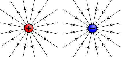
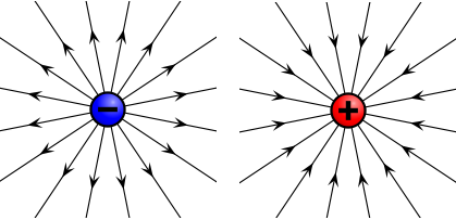
-
Look at the figure below: This is an extract from the figure (a) of the first diagram of my original post. The direction of the forces on the right side agree/coincide, whereas on the left side they collide. The current carrying wire is moving toward a place where the collision will be minimized, whereas the agreement will be maximized. What is here not clear?
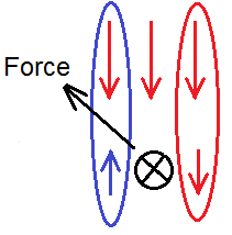
-
NO, it absolutely cannot be arbitrary. (in this answer I will use the words “plus” and “minus” instead of “positive” and “negative”) “Plus” is the effect towards outside (expansion, blowing, explosion, yang), “minus” is the effect towards inside (reduction, suctioning, implosion, yin). For example, the act of inhaling is plus, because our chest expands; the act of exhaling is minus, because it reduces in size. From the history of electromagnetism it is known that Benjamin Franklin (1705-1790) is the man who was the first to introduce the terms “positive” and “negative”, i.e. “plus/minus” in the field of electricity in the middle of the 18th century. Previously, the different types of electricity had been called “vitreous” (meaning “glass”) and “resinous” (meaning “amber”), since the glass and the amber were the most often rubbed objects to produce the opposite electricities. At the time when Franklin gave his contribution, people had actually spoken of two types of electric fluids; however, Franklin argued that there is only one electric fluid, and the excess and the shortage of it in the objects he called “plus” and “minus”. He said that bodies in normal condition have medium amounts of this fluid and are therefore neutral. When two objects are rubbed against each other, one allegedly transfers a part of its fluid to the other and thus the first becomes minus-, and the second object plus-electrified. That these things (i.e. plus and minus in the electricity and in the magnetism) are not arbitrary, I have a proof which I call an ultimate proof. A proof is ultimate when we perceive the truth immediately (directly, unmediated) with our senses, in this case, with our eyes. If we rotate the discs of a Wimshurst machine by turning the crank manually to the right in a dark room (the most noticeable results can be seen at night in a room with a little exterior street light entering it), and if we do this for at least 10-15 seconds to let the eyes get used to the feeble light, we will notice that the horizontal quadrants emit a light flicker, whereas the vertical are completely dark. On turning the crank to the left the flicker relocates to the vertical quadrants, whereas the horizontal ones now remain dark. Looking even more attentively at the scene, we will notice an essential qualitative difference between what happens in the left and the right quadrant (i.e. the upper and the lower one when the crank is turned to the left). The flicker in one horizontal quadrant is directed from the metal sectors outwards, in the other one inwards. In other words, in the left quadrant the metal sectors are dark and the flickering light glows around them, but in the right quadrant the metal sectors are illuminated and around them it is dark. The metallic sectors in the image are drawn as a whole, and not individually, because the light phenomenon appears as a whole; more precisely, as two wholes, one left and one right, and not individually in the sectors. The electricity of the left quadrant (picture on the left) is the same as the vitreous electricity; the electricity of the right quadrant is the same as the resinous electricity. I will not explain how this is determined, because this answer will become much longer (you can check it out here https://newtheories.info). So, Benjamin Franklin did it right. If we fill the middle of a ring magnet (taken out of a small loudspeaker) with iron filings, then we tap the magnet to allow the iron powder to freely take its shape, a difference between the one and the other side becomes clearly visible. At the pole which points North a form of blowing is evident (as if we put the lips forward), and at the pole that points South a form of suction (as if we put the lips inwards). Hence, the plus-pole with an effect outwards is the magnetic South pole of the Earth, and the minus-pole with an effect inwards is the magnetic North pole of the Earth. As a further evidence I want to share an interesting experiment I came across in the book Physik, Volume 2, from the author Hermann von Baravalle (pages 83–84). Look please at the setup below. When high DC voltage is connected to it, then sparks start to jump across the upper part of the circuit. As soon as the poles of the voltage source are reversed, then sparks start to jump across the lower part of the circuit (circuit below). The two different kind of ends where the sparks jump are a thick sharpened wire (or a nail) and a round metal plate. The distance between the nails and the plates in both branches is the same. In this experiment we see that the sparks appear only in the branch where the Plus is connected to the nail, while the Minus to the metal plate. Since the Plus means blowing, the Minus means suctioning, it is much easier for the electricity to bridge this gap than the other, because very high pressure is created at the sharpened point. We all know that the water-jet which comes out of a pipe will reach farther if we narrow the pipe. This comparison is valuable for understanding of what happens. At the same time, the suctioning is greater if the suctioning area is bigger. Here is another evidence that the electricity flows de facto from the Plus to the Minus pole of the battery. When a carbon arc lamp is connected to a DC source, the positive carbon electrode dissipates, while the negative electrode remains pretty intact. When this lamp was used in the 19th century as a street lamp, they had to move the positive electrode closer from time to time, since the positive electrode's dissipation had as a result increased distance between the electrodes and the lamp stopped to shine (i.e. with the increased distance the applied voltage was not sufficient to make an arc). This is approximately the form of the carbon electrodes before and after some time of use: When the electrodes are connected to an AC source, then the electrodes dissipate equally and there develops no difference in their form. Let me jump to the question what a battery is. A battery can be regarded as a container of dissolved agent (acid, base or salt) wherein two plates of different metals are partly immersed. Instead of one metal plate, a graphite rod can also serve. Just as there is an exception to every rule, so it is in the electromagnetism. Carbon is a special and unique case of a non-metal that is conductor of electricity. Consequently, it is also a good electrode in a battery. When two rods (say graphite and zinc) are partly immersed in a dissolved agent, then the part of the graphite rod which is outside the liquid is polarized in one sense (plus), the immersed part in the opposite sense (minus). For the zinc plate applies the opposite. The two rods of the battery can be imagined as two fans. The one that is blowing outside the liquid (positive electrode = graphite), it is suctioning inside the liquid; the one that is suctioning outside the liquid (negative electrode = zinc), it is blowing inside it. When the electrodes are connected with a metal wire, a closed flux is created. And look now: if we open a "dead" carbon-zinc AA battery, we will see that the zinc jar is completely dissolved, while the carbon rod in the middle is quite good. Why so? Because the part of the zinc jar which is in contact with the acidic solution behaves as positive and the movement is always from the positive to the negative. I have recently found an evidence that also Franklin, contrary to the claims of many people, didn't assign the positive sign to the vitreous and the negative sign to the resinous electricity completely randomly. Here is a quotation from the book "THEORIES OF AETHER AND ELECTRICITY - FROM THE AGE OF DESCARTES TO THE CLOSE OF THE NINETEENTH CENTURY" from E.T.Whittaker (1910) The bolding of the text stems from me. As I found in the dictionary, a "wax taper" means a candle. Therefore, the flame of the candle is blown away from a vitreously electrified object; however, it is blown towards a resinously electrified one. Franklin's remark that his interpretation of the observations is somewhat conjectural can only mean that he was not completely sure and wanted even more experimental evidence. Please watch this interesting video: When the plus-end of the cable was immersed in the water, then the lightning was outside the cable (as pictured in my figure (a) below. When the minus-end of the cable was immersed in the water, then the lightning was inside the cable (figure (b)). and the end of this video: Please watch also this video about the Lichtenberg's dust figures: The only “evidence” of the contemporary physics, that the electricity flows from the negative to the positive, is the cathode ray tube. I will start soon a topic about the cathode rays.