
Enthalpy
Senior Members
-
Joined
-
Last visited
Everything posted by Enthalpy
-
Hello everybody! Cryptography uses one-way functions to compute a trace (or message digest) of some "message" (bunch of data). One use is to sign the shorter trace to authenticate a complete message. An acceptable one-way function makes it practically impossible to choose a message to produce a given trace. Nor does it allow to choose two messages to produce any identical trace. One-way functions combine many operations to make the trace a complicated function of the message. If an attacker finds some relation(s) of computer-manageable complexity between the message and the trace, he can produce a reduced set of messages that have better chances to obtain a given trace or identical traces, and ruin the one-way function. Said relations can just be slightly abnormal correlations. ========== Traditional attack methods against one-way functions and other cryptographic algorithms include linear analysis and differential analysis. They are "linear" for the Xor, as arrays of bits are vector spaces with Xor and And operations, and this offers efficient computation algorithms from linear algebra. All present cryptographic algorithms are tested to resist linear and differential analysis. Non-linear relations offer more possible attacks against one-way functions and other cryptographic algorithms. If the message is M (typically >= 128b including padding) and the trace T (usually 160 to 256b), such relations may look like, just more complicated: (M7 or M23 or M78) and (M97 xor M113) correlates abnormally with T16 and T53 or T153 and T192 I propose (but have an intuition other people already did) to let machine learning search for such relations. A neural network is a set of nonlinear relations, machine learning establishes them from a training set, here a set of messages and their traces. The size of the needed neural network is banal presently. The training set must suffice to reduce the false positives, which are best eliminated by subsequent tests on different training sets. Looking for faintly abnormal correlations demands a bigger training set, checking only for more strongly abnormal correlations and searching for many of them seems a better bet. The standard neural networks would only try to reproduce individual bits at the trace from logic functions of the message. On can expand the individual trace bits with a limited set of their logic combinations. Seeking for arbitrary logic functions of the trace bits would need to adapt the neural networks and their learning methods to be more symmetric, as far as I know (and I ignore much). ========== All usual one-way functions I know are heirs of MD-2, MD-5 etc. They use too simple elementary operations: Add, Xor, Rot, from a time when these were faster on a computer. Consequently, the amount of diffusion and confusion of these functions is low - conceptually, the exact logic function from the message to the trace isn't complicated enough. I understand it as a consequence: all historical one-way functions have been broken, MD-2, MD-4, MD-5, in perfectly exploitable attacks, with examples of collisions. Even the early Sha is weakened. As opposed, no established symmetric encryption algorithm, relying on tables or multiplications that provide much diffusion and confusion, was efficiently broken (only the too small DES by brute-force, not by an inherent weakness). That's why I suggest to attack one-way functions, not symmetric encryption algorithms, by machine learning. Better one-way function design has been known for decades. Forget the historical schemes, use a symmetric encryption algorithm as a one-way function, for instance AES. Some fixed conventional value feeds the plaintext input, the message feeds the key input, the cyphertext output is the trace. Known layouts provide a trace wider than the ciphertext output if needed. Known methods cope with messages of varied length. Marc Schaefer, aka Enthalpy
-
Do not delete the file, unless you know exactly the consequences. I did on my first computer after owning it for a week, it couldn't start any more, I had to (learn to) reinstall everything including said hibernation file and Windows 95, it took me two desperate weeks at a time Internet wasn't available and no computer freak existed in the vicinity. On my laptop, the Bios checked for that one file and wouldn't start Windows without the file. In addition, the means to create the file destroyed the rest of the disk contents. Meanwhile, Windows may also create a hiberfil.sys, but I wouldn't take the risk. To the very least, make absolutely sure that the file isn't needed by the Bios. More generally, if a file is needed by a program, it's better to use some tuning provided by said program than to delete the file, which would have consequences, possibly at a time when you've forgotten the deletion and made other changes.
-
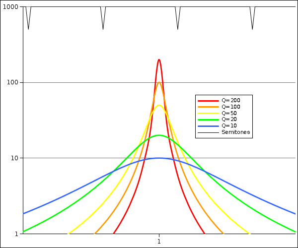
To reduce losses at woodwinds and brass instruments, I have suggested walls and stiffeners of damping materials. It's not that clear. Depending in the frequency mismatch between a mechanical resonance and the fundamental or overtone to be preserved, material losses can increase or decrease the power picked from the air column. Here's a graph of the conductance G = Re(Y) of a series RLC circuit representing the absorption by a wall, around a mechanical resonance and for different Q. The black dips indicate semitone spacing, the mechanical resonance falls randomly among them, I displayed them half-way between aligned and anti-aligned. With side holes, oval deformation of a metal tube needs an amplification factor >30 to begin to act, the bending of the body too. Against these losses, a damping material is good. At bends, I estimated an amplification =30 and even less acts strongly. Damping can be useful, but not far from the resonance, where it worsens the loss. At a flare, even an amplification <10 has a big effect, hence also far from the resonance. There, Q=50-200 can outperform Q=20, but not near the resonance, and Q=10 is still best. Nothing simple hence. Stiffness looks desirable in all cases. ========== According to Schilke's trials, beryllium bronze outperforms sterling silver at a trumpet flare. Silver dampens much, beryllium bronze very little. Beryllium bronze is stiffer (E~135GPa) than the usual luthier copper alloys. This might fit my thoughts here. Beryllium bronze is expensive, uneasy to work, and bears the doubtful reputation of being unhealthy. Cu-Cr alloys are stiff too: 130GPa for Cu, already CuCr1 offers 140GPa while CuZn30 drops to 115GPa. But CuCr1 isn't as light as CuBe2. ========== Series-produced instruments are known to vary. Maybe the tiny differences in hole positions, undercut... explain it, especially through the alignment of the overtones. Or maybe the body's mechanical resonances, aligned or not with fundamentals and overtones, play a role? The dispersion of wood's stiffness, of worked metal sheet thickness, shift the resonances easily by a quartertone. This suggests to fine-tune the mechanical resonances so they fall between the important sound components at design pitch. Near the end of the fabrication, measure the significant mechanical resonances, decide how much to shift each, run software on the matrix of resonance sensitivity to mass, add or remove the right mass at the right locations. ========== My ramblings here are just paperwork. Experiments decide. Marc Schaefer, aka Enthalpy
-
Some brass luthiers allege the flare's material matters especially. Here are some physics arguments. The acoustic pressure acts axially on the wall where the section changes. This creates mechanical movements that produce a volume oscillation where the section changes. Mechanical resonances amplify the movements and shift its phase, so the volume oscillation acts as a loss and dampens the resonance of the air column, as already explained for other wall effects. The force at the flare can also produce a volume oscillation at a bend and reciprocally, as they are mechanically coupled. Not considered here. When a section varies slowly as compared with a quarter wavelength, the pressure of a propagating wave varies as the reciprocal of the diameter. For a standing wave in a conical tube too. This law shall serve for the explanation. As the area varies with the diameter squared, a wave pushes more strongly at the flare than at a bend for instance, proportionally to the diameter. The effect of axial wall movements on the air column's losses too increases as the diameter. That's why flares and their material matter. At the top of a trumpet's conventional range, the fundamental has a pressure antinode where the flare is about 3* as wide as the leadpipe, more at the overtones. The effect is roughly 9* as big as at bends, which I already estimated important. The air column's input impedance has only dropped by roughly 3 at such frequencies, so I agree that flares and their materials can matter a lot to brass instruments and woodwinds too. If a resonance with Q=30 fell in this range, some notes would be unplayable. ========== One can stiffen the body to raise the resonances. The flare itself is very stiff axially. An unhelped bend, loaded by the flare, would resonate very slowly, but brass instruments bind the tube sections to an other. At the trumpet, the binding elements are skewed, almost parallel to the tubes. This suggests that luthiers have known my story here for a good century. The binding elements could hold at the tubes through tangential sheets for stiffness, as I propose in the previous messages. They could also be trusses or sheets rather than skewed bars. ========== One can also dampen the mechanical resonance. For the trumpet, the musician's lips do it at the leadpipe which is connected to the flare. I suggest to use damping materials at the binding elements. Sterling Ag, PCM, NiCo, CuMn... as mentioned in other messages. This would hopefuly be cheaper and more efficient than flares of damping material. Marc Schaefer, aka Enthalpy
-
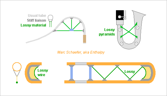
How to reduce the losses at the bends? Difficult and unsure: determine the mechanical resonant frequencies, check where the air pressure nodes are at these frequencies, locate the bends where the air column excites the mechanical resonances less. Though, the instrument has many mechanical resonances and it emits many notes containing many overtones. Choose bend radii that couple little with the air column at the mechanical resonant frequencies. Could this explain the quest for very big radii at the slide trombone and others? The difference of path length doesn't explain it well, the air flow neither. Just an unsubstantiated hypothesis from me. Stiffen the instrument. Some luthier try harder already. I proposed improvements here on Jun 13, 2021 scienceforums Fewer mechanical resonances remain in the sensitive frequency range, and at higher frequencies, where the air column is lossy anyway, they hurt less. Better: the stiffer instrument moves less, that's equivalent to thicker walls without much added weight. Two bores in one wooden part excel for that, as at the boot of the bassoon and old baritone oboes, and I proposed to build contrabass clarinets the same way. Dampen the mechanical resonances. My estimate from last message suggests a big effect with Q=30, but with Q=3 it would be small. ========== Its material can dampen the resonance of the tube. I consider this is the effect of plain silver tube. Whether thin silver plated over 0.3mm brass acts at all, and by this effect, I doubt it. Miyazawa's PCM alloy improved a flute headjoint more than sterling silver did in my trial, so it could be tried at bocals, at brass instruments... Rumours, nothing more, want it to comprise 65% Ag, Cu, Au and Pd. Sadly, I didn't tap the PCM headjoint to compare its poc poc with sterling silver. Cheaper materials dampen vibrations too, at least for strong amplitudes. NiCo resists corrosion, it can be brazed and plated, maybe it dampens if electroformed too. CuMn is know too, but it needs plating against corrosion. ========== If adding stiffeners to the tube, they could concentrate a bit of damping material where it acts best, especially for costly sterling silver and PCM. The preferred location is where the material deforms most for a given tube deformation, and the section must let the damping material contribute most to the tube deformation. Examples: Stiffeners on long tube are better irregular so no uniform half-wave fits in between. For a slide trombone, the stiffeners should leave elasticity, so the moving part can dampen the standing one too. If stiffeners converge, say at a saxophone or bassoon bocal, the lossy material can be at the node instead, if the node provides most compliance. ========== Stiffeners can use materials unsuited to tubes. Cast Zn maybe, useful at thick parts, while corrosion seems to exclude Mg alloys. Some elastomers excel too: perfluorosilicones, silicones, polyketones, many elastomers - with proper shape and coupling with the stiffer metal. Baroque trumpets wrap heavy rope around the tubes: for that purpose? Modern materials could save this weight. Marc Schaefer, aka Enthalpy
-
As usual, you revert to rhetorics when your misconceptions are disproven. Rhetorics is not a part of physics. And please read the topic before re-asking information already given.
-
Rest mass is unaffected. Inertia depends on rest mass + kinetic energy. This is the basic and historically first reason to build accelerators bigger, as the bending magnets can't keep a small radius as kinetic energy increases despite the speed remains nearly constant. If you didn't grasp this, why do you troll threads about Relativity? And for your information: every single form of energy contributes to the mass, without exception. This is why you were asked during your studies to compute reaction energies by comparing the masses of reactants and products. A uranium atom contains kinetic energy, electromagnetic energy, the energy of the strong force, rest mass of some constituents. If any component didn't contribute to the mass, the computation would be wrong. This is established physics. Not you extraordinarily heterodox claim, that kinetic energy wouldn't contribute to the mass and its gravitational effects.
-
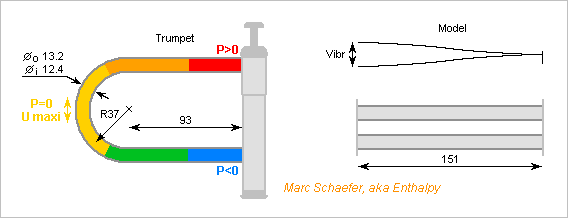
Figures about the effect of a bend at a trumpet. The trumpet is (the photo of) a YTR3335, the bend is the last before the flare. From counting pixels, the outer diameter at mid-bend is already Do=13.2mm. I take 0.4mm thickness (matters little) hence Di=12.4mm. These are uniform in my model. CuZn30 (8530kg/m3 and E=115GPa) gives the section, in SI units, EI=37.9, µ=0.137kg/m and sqrt(EI/µ)=16.6. The bend has mean D=74mm R=37mm, is 2*58mm long, and the straight sections to the pistons are 93mm long. I model the resonance modes by zero movement at the pistons and no rotation at the far "end", due the continuity of the lower and upper pipes. The far end includes a half of the bend, as it contributes mass and compliance, so X=58mm+93mm=151mm. The proper modes follow then nearly kX~(N+1/2)pi/2 with N>=1. Considering for instance N=1: k~15.6rad/m and this mode resonates around 643Hz, unfortunately the range where the air column of a trumpet has the smallest losses. As computed here on Jun 28, 2021, scalable Ps=1Pa and kR=0.43 (now k in air with 348m/s) act on the bend as Fs = 0.82*Ps*S = 99µN The static deformation, without any resonance of two beams each 76+76mm long is 0.38nm. The hands dampen little there, so the brass' resonance brings easily Q=30 and the deformation is 11nm with 90° phase shift. The movement of the bend provides an increasing volume where the instant pressure is higher, that is a loss. I take the same 0.82*S, that is 99mm2. A better computation would be similar to Jun 28, 2021 here, and thermodynamics might even prove both figures must be equal whatever the shape. 11nm deformation, 99mm2 and 643Hz provide 4.4mm3/s lossy conductance for the initial 1Pa. That contributes to 227MOhm, very close to the 150MOhm input impedance reported in "Interactions between wind instruments and their players" by Wolfe, J., Fletcher, N.H. and Smith, J. The pressure antinode may not reside at mid-bend. At random within 180°, it has 50% chances to reside within +-45°. Then, Ps*S and the force are sqrt(1/2) as big, the effect of the movement on the loss too, so the conductance is half as big. 454MOhm is still a big contribution to the 150MOhm. Notes don't match exactly mechanical resonances. But semitones are F*1.059 apart so some note is F*1.029 close to a resonance and excites Q=30 efficiently. This bend resonates also at estimated 1.8kHz, 3.5kHz... The trumpet's first bend after the leadpipe begins at lower frequencies. All tubes, especially the longer slides, resonate as well. This cumulates dozens of resonances within the hearing and playing ranges. Notes have many overtones too. Chances are that most notes have several components damped by movements at the bends. The reported effect of the wall material too fits qualitatively my model: Thin plastic vibrates more, the sound is dull and the instrument consumes much breath. Thicker walls vibrate less, the sound is more brilliant and the instrument consumes less breath. Silver dampens the vibrations (it sounds "poc poc" instead of "ting ting" when tapping) so the walls absorb less power and the sound is brighter. Marc Schaefer, aka Enthalpy
-
Wow, so much interest for this topic! Here a few answers - I probably forget some interrogations. Much is also in the early messages. My preferred particles are (since the beginning) protons at the LHC, as they give an easier wavelength. Other particles are interesting too: Pb ions at the LHC, electrons at the future CLIC. I had also thought at alphas at the LHC. My central idea is that horizontal near-light speed lets the falling particle emit more light than if dropped from zero speed, just as the synchrotron radiation increases sharply with the particle energy. This gives a chance to observe the effect. The protons fall freely over 30m horizontal path. In the 100ns, they lose 50fm altitude, not 30m. The energy a proton may radiate comes from its kinetic energy, just like when magnets deflect the proton. A speeding particle falls in a gravity field with the same vertical acceleration as an initially immobile particle. This is not a far hence uncertain consequence of Relativity but its fundamental hypothesis, that we can't notice locally a gravity field uniform enough. That is, if some unknown matter somewhere in our galaxy attracts our Sun, the Earth with the LHC, an initially immobile particle and the speeding particle, all get an identical contribution to their path from that unknown matter. If anyone believes the speeding particle is less accelerated by gravity, he's kindly invited to propose his theory to replace Relativity. The kinetic energy of the electrons makes 2ppm of the mass of a lead atom but 0.1ppm of a carbon atom. I hope everyone agrees that kinetic energy increases the inert mass of objects: that's why particle accelerators must be big. But the identity of inertial mass, active mass (which creates gravity) and passive mass (which experiences gravity) has been proven identical to 10-13 experimentally. So kinetic energy creates and experiences gravitation. That's why lead and carbon atoms fall to Earth with the same acceleration. Swansont, this is a persistent misconception from you. Miscalling it "established physics" won't help you admit it and then debug it. Every single experiment up to now tells that kinetic energy experiences gravitation, and to a very high accuracy: that's the "equivalence principle". I know that, for some reason, some people here believe a thesis more easily when other people than I explain it, so here are few external sources: arxiv.org Wikipedia or just google for "inertial mass" "passive mass" As for the massive star not collapsing to a black hole for a speedy observer: I've heard of models for immobile black holes and spinning black holes, not for speeding black holes. Many subtleties can happen, gammas apply or not and to what, that make the argument uncertain. Even if the increased mass of the star didn't create a stronger gravitation, the star is flatter in the speed direction hence denser, which would increase the gravitation field and should let some stars collapse. But this doesn't happen, so clearly the models known for immobile black holes don't apply as is to speeding ones.
-
Nearly all brass instruments have bodies of thin tube, where the dispersion relation of bending waves simplifies. mu*w2 = EI*k4 where mu is the mass per length unit, w=2pi*F and k is the wave number: k*lambda=2pi. For a thin tube, mu ~ 2pi*R*e*rho and I ~ pi*R3*e where R is the radius, e the thickness and rho the density, so EI/mu ~ R2*0.5*E/rho w ~ sqrt(0.5*E/rho)*R*k2 with: Sqrt(0.5*E/rho) ~ ============================================ 860 Polypropylene 940 Ebonite 1000 ABS 2300 Vectra LCP, isotropic 2020 Sterling Ag 2596 CuZn30 2620 CuZn20 2753 CuNi18Zn27 2640 Ni (Co?), electroformed 3400 Ni (Co?), laminated 6200 Graphite filament winding ============================================ Sqrt(m/s) Thickness affects resonant frequencies little, so metals are faster than polymers. Graphite composites and anisotropic LCP are even faster. E/rho is the squared speed of a compressive wave, it's about the same for laminated alloys of Fe, Ni, Co, Ti, Al, Mg and for Ni electroformed slowly at +40°C. Cu alloys are a bit slower. Faster alloys are impractical. ========== A wave can propagate as quickly in air as if it bends a tube. Several half-waves fitting in a bend cumulate their effect then. w = kc with c ~ 348m/s in exhaled air, so velocities coincide if sqrt(0.5*E/rho)*R*k = c. * For CuZn30 and 2R = 12mm, k = 22/m, F ~ 1.2kHz and lambda/2 ~ 0.14m. * For CuZn30 and 2R = 20mm, k = 13/m, F ~ 0.7kHz and lambda/2 ~ 0.23m. These frequencies are well audible, they fit fundamentals or harmonics, and some bends are longer than the corresponding half-wave, so I expect this coincidence happens. The effect must matter more at a chromatic horn whose curves contain many half-waves. Marc Schaefer, aka Enthalpy
-
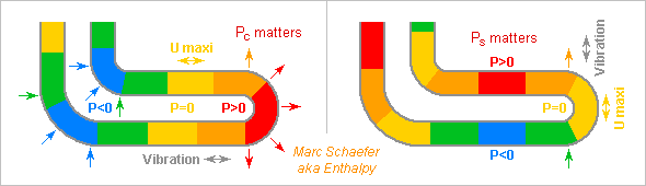
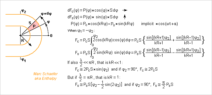
This illustrates how the distribution of air pressure pushes on the bends of a tube of constant section. Less pedantic, more visual than the former message. The standing wave has, at some instant, the locations of its maximum pressure (antinode) indicated in red, of its pressure nodes and maximum speed in orange, and of its minimum pressure (antinode) in blue. In the left case, the pressure distribution component Pc*cos(k*R*phi) matters. The higher pressure in the right-hand bend pushes it outwards because the outer curve has a bigger area than the inner curve (the previous message's computation is less direct but easier). The lower pressure in the left-hand bends pushes them inwards. The forces add to drive the tube vibration horizontally. Its response depends on its proper modes. In the right case, Ps*sin(k*R*phi) matters. The overpressure at the bend's top pushes it up, the underpressure at the bottom too. The shape may well create tube resonances with a vertical movement component there, and these resonances are excited. Shorter air wavelengths may fit mechanical resonance frequencies better. Several half-waves in a bend cancel out their effect partly, not fully. Local forces can also create more local deformation, for instance to open a bend: luthiers put stiffeners there. Local forces can even add up if the wave numbers match between the air and a tube's bending mode. Marc Schaefer, aka Enthalpy
-
At bends, a wave in an air column creates net forces on the wall even if the section is uniform. This applies to woodwinds too. Imagine the small angle element is physically closed at its entrance and exit. The acoustic pressure inside won't let the closed volume element accelerate, so the sum of the forces on the entrance and exit sections compensate the net force on the wall, hence the two initial formulas. They tell already that where and when the acoustic pressure is positive, a bend is pushed outwards the curve, and where and when negative, inwards. For instance the ends of a bend are pushed away from an other by an acoustic pressure positive in the whole bend. Or a full loop of tube gets a net force if the acoustic pressure is positive at one side and negative at the opposite side of the loop. Drawn examples could come, in the future hence maybe. With similar sections, the forces resemble the ones I described at woodwinds' tone holes. The many bends, the narrow long tubes give brass instruments many reasons to vibrate. On the picture, I give a few net forces integrated over a bend, for the cos and sine components of a sinusoidal pressure distribution. Extreme cases give the expected value. The example for the vertical (on the drawing) force takes a pressure negative at the lower end of the bend and positive at the upper end, that is, the air speed is maximum around zero angle. The air's inertia is consistent with a vertical force. The forces could have been computed equivalently from air speed, as is done for a rocket's thrust. The tube's vibrations created by the acoustic pressure act also on the air column's inertia. As I described about the oval and bending deformations of woodwinds' walls, resonances at the tube amplify the deformations and change their phase so the effect is to weaken the resonances of the air column. I should explain that some day, hopefully. I'm pretty sure luthiers have known that for over a century, because they add stiffeners to brass instruments at corresponding locations and orientations. But when I read many research papers three decades ago, I didn't stumble upon the equivalent of my explanation. Marc Schaefer, aka Enthalpy
-
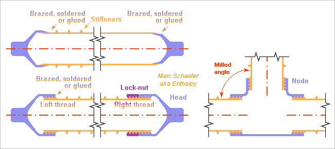
Friction welding, as in the last lessage, saves raw material and keeps the full tube strength. Big series, as in architecture, justify the special machine. Smaller amounts, as for a launcher or a satellite, can more classically use the big outer or inner surface of a tube to exploit the full section's strength. Top left on the sketch, smooth tube heads fit in or on the tube ends over enough length. Or the tubes can fit at the truss nodes directly, without tube heads. Low-temp filler exists to braze aluminium. A nickel layer on aluminium lets solder wet and adhere. Glue could be considered too. Bottom left on the sketch, left and right threads too let adjust the distance and orientation of the heads or nodes. The rotation can be stopped by brazing, soldering or glueing, or with a lock-nut, which a metal wire can hold to the nut. Right on the sketch, the tubes connect the nodes without heads, with threads as displayed or without. An isostatic truss and short overlaps help insert new tubes. These processes assemble the hardest alloys, without the possible limits of friction welding. If wall buckling limits the compression strength, stiffening rings can help with little added mass and effort. This needs experiment, as theories fail. A bigger effort lets mill integral stiffeners in the wall, like an isogrid, or cut a truss from the wall, which a laser or water jet achieve too. Marc Schaefer, aka Enthalpy
-
Kinetic energy creates gravity. You can measure on scales its contribution to the mass. The kinetic energy of baryons in an atom is easily measured. Relativistic particles too fall with 9.8m/s2 on Earth. This results directly from the relativity principle, as explained in the first message. It's 12 orders of magnitude less than the proton's kinetic energy. Where would you suppose the energy of the synchrotron light comes from, when a magnetic field deflects the relativistic particle?
-
More of the magnificent tárogató, by Erdő Zoltán now Remembering - Remembering II - Folk song Wow!
-
As seen from the lab, the particle falls at 9.8m/s2 despite being heavier. As seen from the particle, it accelerates much more than 9.8m/s2 to drop by the same height in a shorter time, and this happens because the Earth moving quickly is heavier. Frequency: the wavelength for a free fall over 30m horizontal distance is around 540nm. It's a benefit from the synchrotron effect, and the reason to make the experiment at an accelerator, as I propose. Without this effect, the radiation would be impossible to measure practically, as the other people noted before my proposal.
-
Ni serves to make multilayer ceramic capacitors (MLCC). Depending on the manufacturer and the model hence the use (radiofrequencies), it can constitute the stacked electrodes and the barrier against diffusion and dissolution against solder at the terminals. The stack of electrodes and dielectric is sintered at once from nanopowder, while the barrier is electrodeposited on the sintered metallic terminals. TDK - Murata - Johanson Ni is ferromagnetic, which badly increases its losses by Kelvin effect (skin effect) at radiofrequencies. Pd was an answer for the terminals of radiofrequency capacitors but is abandoned due to cost. Maybe Ni alloyed with Cu or Mo brings something. All Ni-Co are ferromagnetic, but 38% Cu or 20% Mo make Ni nonmagnetic (electronic components must operate at -55°C, these amounts are for RT) and they keep the melting point of Ni, so the change is hopefully easier. Ni-Mo was already electroformed. polymtl - worldscientific Mo conducts electricity like Ni does, it behaves even better than Ni in liquid metals (solder) and it resists corrosion nicely, so maybe NiMo is good too. Marc Schaefer, aka Enthalpy
-
Sure. But twice as sensitive would already be fantastic, and many people try very hard to improve less than that. In a noise-limited experiment, signal *2 means experiment time /4. At a neutrino detector, or at the LHC photon-emitting free fall experiment I propose, this changes everything. In other uses, a narrow frequency response is perfect. It's often the case when the setup produces its own light. If a Led or a laser diode emits narrowband light to measure ranges, detect remote items... a resonating detector would further help the desired filter.
-
A retina with semiconductor anodes can integrate many (millions of) pixels, if the size is reasonable (optics) and the fast signals reach the circuitry. Maybe through vias can carry the signals from the diodes to the rear face, and the counters and associated circuits reside there or on a stacked chip. Optionally, a minimum circuit (transconductance amplifier, single transistor...) can be on the front face at each diode, to reduce the input capacitance and send a stronger signal through the via. But if the fabrication process achieves it, the whole circuits better reside next to the diodes. Digital processes not too old make a 40+ bit counter much smaller than a 4µm*4µm pixel. A 1µm deep Pin diode isn't standard in recent digital circuits, but these diodes need no optimized properties, and fast Mos transistors are good as preamplifiers. Counting 10G/s is reasonable. The photocathode can reside close to the anodes, like 50µm, and then a few kV give the photoelectrons straight paths. The pixels could be smaller and more plentiful if the optics is good. The pixels don't interfere, and the dynamic range is far better than a Ccd. I hope cooling lets detect single photons over hours, fantastic for astronomy, better than a Cmos retina. Many uses need fast reading, but at least the data is digital here. A Gddr interface suffices, few USB too. Marc Schaefer, aka Enthalpy
-
At least one paper claims to "prove" that a falling charged particle doesn't radiate for an equally falling observer. It's a hypothesis by Relativity that we can't notice locally a gravitational field uniform enough, so said "proof" is a tautology. The LHC sits on Earth, it's not free falling.
-
The detector with photoemissive cathode, acceleration voltage and semiconductor anode is excellent to make imagers: the circuit for each pixel is simple, and the detection of individual primary electrons gives outstanding sensitivity and linearity. If a retina covers much area, the semiconductor anodes can be smaller, and they potential attract the primary electrons. ========== Circuits The fastest amplifiers must sit at or behind the anode, or just besides, with one amplifier chip per anode. Scanning 1D imagers may afford that. In the 1ns response time range, 50mm printed lines reach several pixels, and for instance a BGA170 Dram package can host 20 analog inputs and outputs. BF998 performance suffices and is easily integrated. A 2D imager is conceivable. At 10ns response time, packages with 1500 balls can host 200 channels, and a 2D imager becomes reasonable (which doesn't mean "cheap"). The circuits can add ADC modes to the counters to extend the dynamics, with one or several lower-gain outputs without comparators. Because the input signals are fragile, I prefer to integrate the comparators on downstream chips with the counters. The amplifiers, comparators and counters can integrate 2* to 4* as many channels in a package of same size. Or rather, the counter chips would have bigger packages. All channels on a counter chip can share a bus, for instance USB. ========== Particles Cooled photocathodes exist for the near-infrared. At visible light, such an imager can have single-photon sensitivity, say for night vision. Would it outperform CCD imagers for astronomy? With some scintillator or other converter, individual ionizing particles are detected. Sensitivity and speed would make nice Positron Emission Tomography. Marc Schaefer, aka Enthalpy
-
The polarization analyser shall remove much of the stray light created at the bending magnet, as on the diagram of 06 March 2016. After the last deflection and focussing magnets, which produce much stray light of badly defined polarisation, a first set of diaphragms (ex collimator) shall remove most light, before a long and weak bend magnet turns the particle beam away from this stray light. This bend magnet has a very stable orientation and, somehow, a field of uniform orientation. Field uniformity is less critical if the wavefunction of each particle is delocalized over the beam width. If this is achieved, the stray light is produced essentially by the bend magnet, with accurate polarization, so an analyser can contribute remove it. On 21 February 2016, I had suggested 120dB cleaning by the analyser, but meanwhile the diaphragms provide 154dB in my estimate, so the analyser can provide about 100dB. Since semiconductor patterning achieves 5nm over 20mm, and a milling machine few µm over 1m, an accurate analyser is feasible. It must also keep its orientation to 10-5rad, or 10µm over 1m, which is less difficult than a laser resonant cavity. The adjustments are not done with 5*10-6 photons/second. To adjust the analyser, the diaphragms are widened, so up to 2*1012 photons/second from the bending magnet emerge from the analyser to an auxiliary detector. To observe the efficiency of the diaphragms, light is measured before the analyser, where 80 photons/second from the bending magnet are still present. ========== Maybe more diaphragms, packed more closely, or a continuous black part, perform better. ========== The geomagnetic field must be shielded, say to 0.25pT so it creates 0.1* as many photons as gravity does. The shielded section includes the last diaphragm section and the free falling section up to the optical deflector. The Lorenz factor eases that because the Earth attracts the kinetic energy too, or as seen by the photon, because the speeding Earth is heavier. Surrounding cylinders of soft magnetic material can't achieve 0.25pT alone. Hysteresis in mumetal leaves a field about 106* too strong inside. Imperfections in the demagnetization would limit what concentric cylinders achieve, and I believe gaining one million is impossible. Active coils can't compensate the 50µT down to 0.25pT, because the 0.58A beam creates 0.1µT at R=1m, so I believe measuring 0.25pT is too difficult. But just a cylinder of type I superconductor (or a type II used in region I) can expel the 50µT geomagnetic field. Niobium's critical field Hc1 nears 0.2T at 4.2K, for MgB2 it's 0.15T, so to my understanding, the superconductor needs no help by soft magnetic material nor by coils, except maybe near the bending magnet. The cylinder must be longer than the protected section for the field to drop enough. A small diameter helps. Assembled parts can constitute the cylinder if they overlap closely and long enough. Marc Schaefer, aka Enthalpy
-
I like ever more a photoemissive detector, but with a semiconductor anode. Hamamatsu add optional semiconductor avalanche at the anode and call it "hybrid photo-detector". I prefer a PIN diode at the anode with no or little polarisation. scienceforums Hamamatsu indicate dark count rates like 100/s for a GaAs photocathode at -40°C, but 13930K=1.20eV activation energy would reduce this cause to 10-6/s @-78°C and 10-53/s @77K, wow. The emissive area shrunk from 10mm*10mm to 30µm*30µm would also gain 105. In a usual photomultiplier, other sources limit the improvement below some -50°C. The pulse count mode can't remove them all, for instance the stray emission by the first dynode, because the gain per stage is small and fluctuates. The single semiconductor anode will improve that at once. The very constant pulse area by a photoelectron hitting the semiconductor anode lets two thresholds remove most stray pulses by cosmic rays and radioactivity. As the experiment shall produce 5*10-6 photons per second, bunches of pulses within a µs can be all suppressed too. ========== I initially wanted for maximum power a proton free fall as long as possible, 50m, but photocathodes aren't very sensitive to the resulting 900nm peak photon wavelength. GaAs would respond only below 850nm, and with 15% quantum efficiency. Better 30m free fall to emit 0.36* as many photons, but around 540nm, where a transmissive GaAsP photocathode offers 40% quantum efficiency. This gives twice as many counts as GaAs that detects every second photon with 15%. If more length is available, install several mirrors and detectors. Marc Schaefer, aka Enthalpy
-
The semiconductor anode is known. It's the chapter 11 of this handbook, called "new" in 2007: hamamatsu The added avalanche section in the semiconductor increases the gain. For many uses, I'd have no avalanche section in the anode: According to my estimates, it isn't needed in counting mode. It lets the gain fluctuate. Just removing its polarisation remedies this. A thin PIN diode is extremely fast, but a thick avalanche section, even unpolarised, makes a slower current decrease. Does Hamamatsu produce the pairs in a low-field region? They better appear in a depleted zone for speed, hence my PIN. As the primary electron produces most pairs at the end of its path, the PIN region attraction the slower holes, the P, should be there, at least at constant accelerating voltage. So if the I thickness matches the energy, have the N where the primary electron impinges and the P where it stops, for narrower current pulses. On some uses, I'd add a second electronic threshold to reject pulses too strong, since these can't result from individual photoelectrons but rather from cosmic rays, radioactivity or others. Photoelectrons in a PIN diode make highly repeatable pulses, so this discrimination is very efficient. Successive pulses too near to an other could also be removed if they are improbable in the signal. ========== Noise standard Avalanche diodes sell as bad noise standards. I propose instead a non-avalanching hybrid photo-detector as noise standards. Strong noise results from electrons arriving in groups: sqrt(2iQB) where B is the bandwidth and the collective charge Q comprises many electrons. To prove it, I illuminated a wide avalanched diode and observed that the noise decreases, as light provides more seeds and the same current comprises more parcels of smaller Q. Usual avalanche diodes are very sensitive to temperature that creates avalanche seeds and changes Q. Alas, they also produce much heat. Instead, a non-avalanching hybrid photo-detector provides extremely constant Q (the number of electrons fluctuates less than its sqrt). Already the acceleration voltage defines it well, so the light source could be regulated for a given output current. The photoelectron current can be regulated by the light intensity, the pair generation current by the accelerating voltage, to provide an acurate noise density. Seems even better: thermoionic emission could make the primary electrons (or maybe tunnel emission if it becomes reliable), by some filament or LaB6 spike. Trivial to regulate with additional electrodes. The primary electrons can be deflected by usual means to spread the damage over the anode for longer life. I had estimated <10ps charge collection time in 1µm GaAs depleted zone (which can be polarized here). This would provide a noise spectrum decreasing around 50GHz, wow. The noise density resulting from the primary and the pair generation currents is very accurate, much better than from avalanche diodes. Marc Schaefer, aka Enthalpy ========== Hi JC, thanks for your interest! I come back.
-
The semiconducting anode of 23 April 2017 achieves fibre datacomms speeds with nontrivial development. A less fast semiconducting anode is easily developed. It can be a first research step and is useful in many science experiments, for instance scienceforums If the sensitive area is bigger than a halfwave, the photocathode needs not resonate and can be standard photomultiplier technology like GaAs. Just reducing the area improves the dark current. Cooling the photocathode to 77K would do miracles, and then the semiconducting anode and the amplifier would be cooled too for speed and noise. I didn't check how long the PIN survives energetic photoelectrons. It's a worry for datacomms, not for an experiment detecting few photons. ========== A separate amplifier, bonded by wires to the PIN diode, is easier. For instance the FHR20X or NE32400 transistors offer <0.2pF capacitance and low noise as the input of a transconductance amplifier. More time for hole drift enables a thicker PIN diode, like 5µm Ge, that catches more energetic photoelectrons, for instance 24keV producing 8 000 pairs of carriers, while less bandwidth reduces the noise. 5µm Ge needs no external polarisation. Additional 0.2pF allow D=100µm. A window of 0.5µm thin Al can stop stray light, while 10µm Al, for instance a bonding pad, protect the insulators against the photoelectrons. 15 Ohm noise equivalent resistance and 77K create 120pV/sqrt(Hz) noise, so 5GHz noise equivalent bandwidth and 0.2+0.2pF produce 22q rms noise. A threshold discriminates easily the 8000q signal even at 10Gb/s. ========== Much slower: a TLC081 bicmos op amp builds the transconductance amplifier. 12pF input plus 22pF from the PIN diode widened to D=1mm, combined with 8.5nV/sqrt(Hz) at 300K and 1kHz to 10kHz passband create 170q rms noise, nice overkill again. A threshold at 3500q detects every photoelectron, and 20*sigma fulfil all unreasonable intents and purposes. ========== The threshold discriminates parasitic currents, especially if using guard rings. I see only electrons travelling through vacuum from the cathode, and other ionizing rays, that can provoque false detections. Clean detector and shielding materials, and a cold photocathode as small as possible, make the dark current extremely small. Marc Schaefer, aka Enthalpy