
Enthalpy
Senior Members
-
Joined
-
Last visited
Everything posted by Enthalpy
-
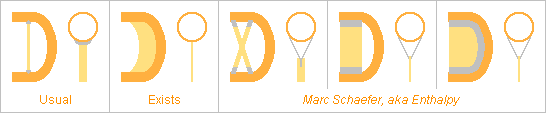
Air pressure oscillations create strong forces in the tube of a wind instrument at the bends, I hope to detail that some day. I haven't seen much consideration about it in academic research, but luthiers try to stiffen the instruments against these forces, more so at brass instruments. The sketch illustrate the stiffeners at a U-turn. More locations use them. The most usual design, first left, provides but more than a stable spacing between the tube ends. The narrow connection to the tube doesn't help the thin wall. The known design, second left, is meant to provide stiffness against the varied orientation of the forces at the bend. It injects force over a longer line at the tube, but still perpendicularly to the thin tube that offers little stiffness. I propose instead to inject the force tangentially to the tube's wall so the flexibility of the thin wall doesn't spoil the stiffness. I give three examples at the right of the sketch. I believe that the parts depicted in grey can be cut and bent from a flat sheet even in the rightmost example. This applies to woodwind too. Marc Schaefer, aka Enthalpy
-
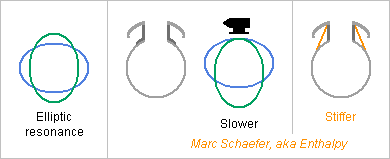
I compute elliptic resonances for unloaded and complete cylindrical sections for simplicity, but real cases are worse. For instance a flute blowhole adds a raiser and a lip plate whose mass lower the resonance. As a cylinder resonates but higher than flute's C, the metal tube around the blowhole resonates within the fundamental's range. Possible explanation why a wooden head emits the high notes more easily. Plus, the harmonics fall well within the resonance range. I propose to stiffen metal headjoints with oblique sheets that start at the raiser, preferably at the angle with the lip plate, and end tangentially at the tube. ========== Several struts ending tangentially at a tube make a stiffer aggregate than the usual single strut ending perpendicularly on some stiffening part brazed on the tube. I suggested it for a baritone oboe, combined with the keys, there scienceforums but tangential ends apply to many more instruments, for instance saxophones or low clarinets, also independently of the keys. If desired, pyramids bring stiffness in all directions. The struts can be tubes flattened at the ends, sheets optionally bent as thicker profile, cast or forged or machined parts: many options exist. Marc Schaefer, aka Enthalpy
-
I proposed that the walls' elliptic deformation couples with the air column, here on Nov 13, 2017 and Nov 26, 2017 and more Here are examples of resonance frequencies (at 4 nodes per turn) for some parts of common instruments. Young's "transverse" modulus isn't well documented for dense wood, I just took a tenth of the lengthwise modulus. Dimensions are from memory. Computed from µ*(2*pi*F)2 = EI*k4 with µ=e*rho, I=e3/12 and k*pi*D=4*pi F Dia Thick Et rho Mater Instrum Hz mm mm GPa kg/m3 ====================================================================== 6k 11.8 0.4? 83 10300 Sterling silver Piccolo 18k 15.3 4? 2.1 1050 ABS Piccolo 16k 15.3 4? 2.0? 1310 D. melanoxylon Piccolo ====================================================================== 2.4k 40 4? 1.7? 975 B. Sempervirens Tarogato 2.3k 40 4? 2.0? 1310 D. melanoxylon Tarogato 4.6k 40 3.7 10 1400 LCP Tarogato 1.0k 36.5 0.5? 114 8550 Brass Soprano sax ====================================================================== 11k 18.6 4 2.0? 1310 D. melanoxylon Clarinet 11k 18.6 4 2.5 1410 Ebonite Clarinet 3.6k 15.6 1 1.3 905 PP Clarinet ====================================================================== 210 80 0.5? 114 8550 Brass Tenor sax 158 81 1? 2.1 1050 ABS Tenor sax ====================================================================== 0.8k 63 3? 2.2? 1025 D. spruceana Bassoon 0.8k 63 3? 1.2 590 A. pseudoplatanus Bassoon 0.7k 63 3? 1.3 905 PP Bassoon 1.1k 62 2.2 10 1400 LCP Bassoon ====================================================================== For thick-walled narrow instruments, the elliptic deformation is a worry mainly at the bell. There, stiffening rings look archaic but can be useful scienceforums Bassoon bells walls are already thicker around the tone holes. Thicker walls at a bassoon's bass joint and bell (not elsewhere) raise the elliptic resonances. Azimuthally stretched polymers, even PP, would improve. Comparison at same mass would be fairer to Acer pseudoplatanus. Thick banal polymers equal wood against the elliptic deformation. LCP outperforms wood of same mass, more so if it can be stretched. Wound graphite fibres would improve bells. Thin injected polymer is bad, as known experimentally. Lower resonance and smaller impedance. Wall losses explain the dull timbre and the lack of blowing resistance. Saxophones are in trouble, with resonances in the hearing and playing range. But at least one excellent luthier (grüssdi!) vehemently denies it. The elliptic deformation is supposed uniform over the whole length. This tells only the lowest resonance. The elliptic deformation can also be offset by 90° between antinodes adjacent longitudinally, which creates many resonances at close frequencies. The tone holes lower all frequencies. Bending modes reshuffle the comparisons. Wood's lengthwise modulus outperforms most polymers. Wall thickness matters little, good for metals. Marc Schaefer, aka Enthalpy Thanks for your opinion!
-
"I proposed" in the first message to wrap electric motors' permanent magnets in carbon fibres... These companies, among many more, may perhaps have come later than my message Tesla model S plaid - Tesla recent model S - Bunting Europe - Arnold Magnetics - Eunda but this research paper dates back to 2006, years earlier, kudos Cho, Myeong, Choi and meanwhile a carbon fibres sleeve gives better pre-stress than wrapped carbon fibres.
-
KOR (Kristian Oma Rønnes) describes a high register hole close to the bassoon's reed in his book The Expanded Bassoon Register (2019) a mobile cover would let it act on demand. Demonstrated by his friend Aleksandr Ziva there lyhQHMyTtq4 the hole also changes the timbre a lot. Shape details should improve that.
-
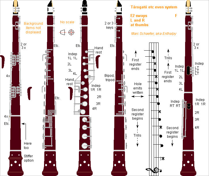
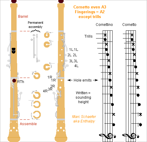
Here's the aspect of a tárogató or an oboe with system E or F as already described. The left hand could close some naked holes, the right hand too on the oboe, but covers here are easier to play, especially as 1L (=left index) and 1R attend two holes each. The number and positions of the register holes need experimentation. The register holes combine with different tone holes on the second and higher registers, so independent keys seem better. Though, automatic register keys might be possible, with different sets for the second, third, fourth registers. If some registers open several register holes, maybe the thumb should close one of them instead of opening it. A narrower bore, a smooth mouthpiece like the clarinet has, undercut tone holes, maybe silver tenons scienceforums shall widen the range and give a richer sound, but the sound may become strident. I believe chambers can more selectively cut the sound's strident components and keep the enriching ones scienceforums and followings as already suggested there, the chambers don't need complete tone holes. They could be bored, then tapped with a stiff sleeve of with water keys. Extra local thickness where the cone is narrower need no extra material and stiffens thin wood against elliptic deformation, especially Acer pseudoplatanus, Dalbergia retusa or Buxus sempervirens, but it looks archaic. To rotate pairs of index keys around one shaft for supposed comfort, the pillars are very tall. Bipods or tripods shall strengthen them. Doubtful choice. The system E is depicted at the left of the staff, rather: a system E2 with left and right swapped at the thumbs, as this seems simpler on the sketch. All keys at the upper fingers are independent. The thumb keys are duplicated, they close 4 tone holes, where any lower key closes every higher one, as suggested there scienceforums If the second-lowest note already octaviates well, the hands can sit two semitones lower, and the right thumb alone close the two remaining low keys. This simpler system F adds only two trill keys at the proximal or medium phalanges of 2L and 3L, needs no hand rests and is nearly the cornetto's A3 system I described there scienceforums But if the lowest note octaviates well, the hands can sit lower one semitone more, leaving a single low key at the right thumb. This system G is then the cornetto's A3 system, just at a different height. Marc Schaefer, aka Enthalpy
-
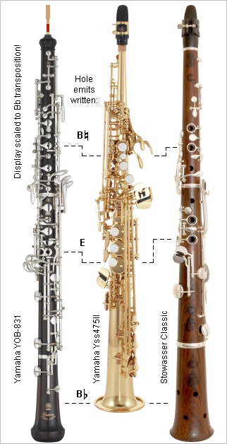
I scaled the pictures of an oboe, a soprano saxophone and a tárogató to sound the same lowest Ab as if the oboe too transposed in Bb. Not perfectly, since the equivalent column length of the double reed probably exceeds the single reeds, and there are some end effects, but the general observations about the tárogató scale must hold. To save covers at the right hand, the tone holes are very narrow and consequently even higher on the column than at the oboe. At the left hand, the tone holes are somewhat narrower than on the saxophone, and about as high as at the oboe. The six bare tone holes are almost equally wide. It is catastrophic presently, so here's how I imagine to improve the tárogató's intonation, especially with my even fingerings E described just above, or the F suggested in the same message, just with one right thumb key more than depicted for the cornetto scienceforums I'm no luthier, so possibly I put nonsense. A bore not as wide as at the saxophone and the present tárogató, to ease the high notes, stabilize their intonation, and extend the easy range. Low tone holes much wider than at the present tárogató for stabler intonation, slightly narrower than at the saxophone for mellower sound, relatively to the bore. Use cups. This combination takes less air from the musician than at the present tárogató. Matching clarinet reeds is a meaningful goal. Maybe the same mouthpiece facing as a Bb clarinet, but the mouthpiece's bore must be narrower. Rather no chamber in the mouthpiece, but a barrel like the clarinet has. Higher tone holes regularly narrower than the lower ones, so the losses match at register jumps, like the clarinet does, more than the saxophone does. Multiple holes increase the losses at identical inductance. Software can help. I still ignore if the tone holes shall be long. But softening their edges improves clarinets. The outer edges too if possible. With inserts? Chambers at the high tone holes can make a mellower sound scienceforums The bore can be slightly narrower and shorter where my even fingerings have tone holes to compensate their volume. Not 1:1 as this increases the inductance too. Adjust the bore profile, especially the barrel and the mouthpiece, for accurate octaves. Decide the fingerings for the upper registers, as the ones I gave are mere indications. Multiple high holes can help here. Adjust the intonation on all registers as Cooper did for the flute, from 1) A measured matrix of sensitivity to hole positions and diameters, and 2) A measured matrix of sensitivity to the bore profile. 3) Software might estimate the matrices, saving measurement time. This task takes time and the tárogató is no mass market. But my even fingerings ease much this development, the tárogató is magnificent, and more people (clarinettists) may want to play the improved instrument. Much here applies to the development of an oboe with my even fingerings. Marc Schaefer, aka Enthalpy
-
Trusses often consist of light tubes with welded stronger ends for assembling at the nodes. Usually, the ends are welded with the tubes by friction, where the tube rotates and the end is pressed strongly until they melt together. This leaves the full tube strength or nearly, even with materials unsuited to other processes like TIG. But the relative orientation of the ends is undefined. If the assembly method at the nodes accepts any orientation, fine. As a second possibility, the ends can have an axial symmetry when they're welded with the tubes, and be milled afterwards with the adequate relative orientation and length. I propose a third possibility: build a special machine that welds by friction both ends simultaneously. The machine rotates the tube, holds both ends with the desired relative orientation, and presses both ends against the tube until the desired length is achieved. The machine must hold both tube ends firmly to avoid torsion in the tube. It could use slotted cones like the ones that hold milling cutters. As I didn't check if this is already done. The uses exceed the rocket structures I proposed. Marc Schaefer, aka Enthalpy
-
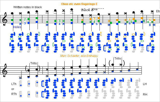
The oboe starts normally its second mode on C#, the tárogató can it too, so the even E fingerings for oboe etc start the second mode on C#, rather than on D. The even E fingerings are like the D, just a semitone lower: One cover less to synchronize, one thumb touchpiece less, welcome simplification. The hands a semitone lower are close to the present position on the oboe. The distances that enable bare holes stay the same, up to 2R on the cor anglais and 3R on the oboe. The tárogató needs wider tone holes than presently anyway, hence covers. The register keys aren't displayed: duplicated at the thumbs as previously. The lone open holes got colours that refer to the notes. If the oboe could start the second register on the lowest note, it would be even better: just one touchpiece at the right thumb, only register keys at the left thumb, no hand rests, no synchronized covers, just two trill keys at left hand, as I proposed for the cornetto scienceforums On the saxophone and the flute, the second register gets bad below D, but the Stowasser holes and an adequate register hole should help the oboe and the tárogató. Or if the second register can start on the but-lowest note, the right thumb just moves two independent keys. Marc Schaefer, aka Enthalpy
-
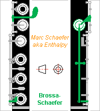
Here's one design for a Brossa-Schaefer keyset for the Boehm flute. It closes the F# cover (that emits G) like the Brossa key does, and additionally it closes also the side G# key to trill F#-G# as I proposed as an option scienceforums The ultimate solution is my even fingering system scienceforums and followings Boehm had designed a G# key open at rest, which was simpler, didn't need a duplicate hole that adds losses, and made easy F#-G# trills. But since Lot, we're used to G# closed at rest, alas. The right hand looks simpler to me at the saxophone than at the flute. Mount the trill keys? Rockstro had added the touchpiece between the "E" and "D" covers (that emit F and E) and shifted the trill keys one position upwards. A Rockstro-Schaefer design is easier. But the Brossa design survives, supposedly thanks to its compatibility, so I sketch a Brossa-Schaefer keyset. The side G# cover keeps its position but is articulated differently and open at rest. The spring of the 4L G# lever closes it (not worse than the split E) and pressing the Brossa-Schaefer touchpiece too. Maybe the 4L G# lever can move around the same axis as the upside G and G# keys, as displayed. Now the Brossa-Schaefer touchpiece is no more the F# key. It allows to close the side G# while the F# key doesn't. This is needed to play the third octave Eb. But the Brossa-Schaefer touchpiece closes the F# key like the F, E, D do, with similar hardware. The Brossa-Schaefer touchpiece is pressed alone for F-Gb and E-F# trills, while the D cover is pressed alone for third octave Eb, so the exact position of the touchpiece matters. Maybe the Brossa position isn't the best one. Beyond the D cover? The undisplayed upside G to G# connection and the split E can remain nearly like now, passing the 4L lever if needed. Marc Schaefer, aka Enthalpy
-
A similar construction can save most assembling labour at the opposite end too. That barrel's end slides in its bored ball. This ball doesn't need to rotate and can be slightly larger so the post and the cap press it, or better, the post and cap have a slightly smaller hollow and distinct shapes. Or could the ball be part of the cap? Provided that the spring doesn't twist the barrel's end. ========== Some coatings resist wear and brazing heat. Nickel doesn't gall but its unlubricated friction is strong. Chromium glides easily, but few alloys don't gall against it: bronze, aluminium bronze - no information about nickel silver. Nickel and chromium can be ground. Countless coatings exist. Nickel doesn't gall against itself because pairing is irrelevant. Marc Schaefer, aka Enthalpy

-
Here the pillar comprises a threaded post, of axial symmetry hence indifferent orientation, and a cap oriented when assembling so its opening accommodates the barrel's head. A ball at the barrel's head accepts misalignments. The post and the cap press directly against an other, leaving the barrel's head a well controlled play. If a drill bit with spherical tip, or any tool that makes the hollow for the barrel's head ball, also makes the surfaces of the post and the cap that press against an other, the play is more accurate. A sheet spring could press the cap on the post, provided it's difficult to remove. At the sheet springs I saw, all bends and folds are parallel to an other, hence the bump in the cap to hold the holed spring. If a spring can have 3 or 4 legs instead of 2, the bump and the hole are superfluous. The head could be welded at the barrel, possibly by friction as already suggested. These parts can be mass-produced by automatic machines, possibly at a subcontractor, and their assembly saves most manual labour. The ball of the barrel's head can be of steel of ceramic for accurate shape and to resist wear. A screw through a hole can then hold it at the barrel's head, maybe at the barrel directly. If the post and the cap wear out, they are just replaced. Marc Schaefer, aka Enthalpy
-
The extra touchpiece for the flute's F# I proposed here on May 19, 2018 is called a Rockstro or Brossa F-sharp key and existed a century ago PH1e0oEiR3I - dwsolo.com The Brossa key is located above the "D cover" as I proposed among several options, while the Rockstro key is between the E and D covers and the pre-existing trill touchpieces move one position higher. The Rockstro arrangement gives more room, the Bossa keeps flautists' habits. As the pre-existing trill touchpieces serve for high Bb, B and higher notes, with awkward slurs, comparisons between both should be patient. The mere compatibility with existing fingerings must have prevailed, because the Brossa key exists today flutesandflutists.com (6th pict) - pettrypiccolos.com It's so easy, why don't I have one on my flute? At least, a good workshop can add it. I haven't seen (yet) this F# touchpiece close G#, which may be my idea.
-
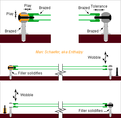
The pillars are screwed in a hole in the wooden body presently, so their orientation is unpredictable. The balls are then bored in the good direction, with manual skill as usual, and can get flat faces, a thread, a recess. If present, the conical screw tip accepts some misalignment. Some designs let align the pillar after it's screwed in the body, at least in patents. My proposal instead: Without a conical screw tip, the ball could belong to a subpart distinct from the pole and be assembled with proper orientation by brazing. An auxiliary metal sheet can protect the wood from the flame. Maybe auxiliary metal like massive pliers, or water in a sponge, can absorb the heat conducted by the pole. Quenching after brazing helps, faster heating means too if available at workshops. 15µm diameter play on 3mm length leave +-1.5mm tolerance at the opposite end of a 300mm shaft. The luthier could wobble that end by +-1.5mm around the other ball in both directions while the brazing filler solidifies, so the play is symmetrical. At and near the ball displayed left, only chip machining defines the play. The materials should resist wear and survive brazing temperature. The screws could be commercial parts, possibly modified, maybe with a Torx, hex socket or cruciform screw drive. The barrel end parts could be brazed, but since the nearby cups and touchpieces are brazed too, welding seems better. Friction welding is seducing, where the parts are pushed and rotated against an other. Maybe a boring machine achieves the speed for the small diameters. Marc Schaefer, aka Enthalpy
-
For really big forces, I'd go back to screws and electric motors. They are not as flexible as hydraulics, but they're more compact. Ball screws would save torque if they're compact enough, which I doubt, so the screw would rather glide against the nut. I got very small friction coefficient from a layer of nickel with embedded Ptfe (or a layer at each mating face, this won't gall) plus MoS2 grease. You may find this very hypothetical synthesis of cubane fun: chemicalforums I ignore if it needs light, for ethylene 2+2 cycloaddition it's 172nm. For fast production, a quick cycle of the diamond anvil brings as much as a bigger anvil.
-
Found with gratitude a glossary shwoodwind.co.uk so in my previous posts: Shaft -> Barrel Cover -> sometimes Cup Lever -> sometimes Touchpiece Post -> Pillar Boule -> Pillar's ball, sometimes Pillar
-
I already used hand pumps, from the catalogue, that create 150MPa (1500bar). Long lever, small piston, big pressure - with stiff parts and good seals. So I don't feel the necessity of sea pressure to achieve 110MPa. A lab and a pump feel more comfortable to me. Diamond anvils are often moved by screws. They achieve pressure far bigger than the Ocean does. The Ocean floor (most is at -3 000 m, while -11 000 m is rare) may have other advantages, like fewer cosmic rays. I'm not quite sure why some countries are interested now (or were few years ago): methane is one incentive, metals may be one other. Above all, submarine war.
-
I'd like to recommend SI units. Not just for my personal interest (never lived in the US) but also for yours. SI units do bring simplicity and are the units of engineering and science. I even switched from mm2 and MPa, which used for mechanical engineering, to m2 and Pa when I began computing resonant frequencies, for mechanical engineering too. So 1000 psi are about 69bar=6.9MPa. That's not much. Hydraulic parts are commonly designed for 21MPa, 35MPa, less commonly 70MPa and 150MPa. You get all seals, dynamic too, and pumps etc up to 350bar anywhere. For 1500bar, you still get static seals from the catalogue. Beyond that (I made apparatus at 350MPa), you must make your seals yourself, which is really difficult. All parts deform a lot too. You get good forces from 35MPa already. Have a look at any crane or truck, the hydraulic cylinders are small, often at unfavourable angles, and they move big weights. Big piston areas are possible. I worked with D=0.4m to create a few MN. Far bigger exists. One serious difficulty is to close the cylinder head: you must exert a force bigger than what the hydraulic pressure will. If not, the pressure just deforms the screws and other parts, creates a slit under the head, and your seal gets extruded through the slit - impressive, and nice result. But just exerting such a force is a challenge, since the screws take already the whole cylinder circumference, so more force needs bigger screw diameter, but these can't be tightened by hand. Up to D=16mm you can, with a 1m long wrench, and you obtain 100kN per screw. Beyond, you need other tools, like a geared wrenched (English name may differ).
-
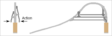
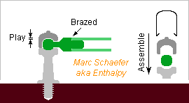
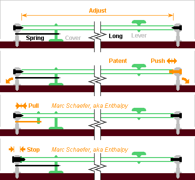
Long keys can get play on woodwinds. On a bassoon, a bass clarinet, on contrabasses... they can exceed 1/3m or 1/2m, but 0.2mm play, perhaps 0.1mm, hamper the operation of the pads at the covers. Compressed shafts don't work properly neither. Both do happen when a wooden body gets less or more damp, perhaps warm too. One good solution splits the function in several assemblies, where the shaft that carries the cover is short. But this isn't always possible or desired. At least one patent integrates some spring that pushes the shaft at the end opposite to the cover. The musician may push the shaft to the sides too, rather strongly if gliding from a lever to an other, so the spring must be strong. This creates strong stress where the posts hold in the wood, not desired over 1/2 or 1 century. And in the patent's drawings, little room is available for the spring. ========== I propose instead to pull the shaft at the end near the cover. This creates no stress in the wood. The spring can reside outside the shaft to have room. I could be the same spring the brings the key to its rest position, especially if this avoids friction or noise. ========== Alternately, the shaft could get stops in both directions at the end near the cover, and the opposite end move freely in the axial direction. In mechanical engineering, this is standard design with bearings. In the sketched design example, the screw in black holds in the shaft and presses against its end while the boule's length is adjusted to let the smooth part of the screw and the shaft glide with minimum play. Usually, the boule is screwed in the body and later planed, bored, threaded. The orientation may then lack accuracy for my second proposal. But other boules exist, in two parts or more, that are already machined and get assembled with the proper orientation after a part is screwed in the body. This would let mass-production machines define the length of the boule and the screw. Marc Schaefer, aka Enthalpy
-
During interventions on a wind instrument, screwdrivers may slip away from the screw and scratch the instrument. Normally it doesn't happen to trained specialists, but operations are slower. The usual answer, for instance at computers, are cruciform screw drives wikipedia and many more, like the inner Torx. Maybe instruments could adopt such screw drives to gain some safety and time? I understand many screws are taylor-made, and the slot head is then easiest, but just a cross head isn't so difficult. Or could the screws be processed from industrial ones? Keep the head and adjust the length and optionally the pointy end. Marc Schaefer, aka Enthalpy
-
Hi IDNeon, thanks for your interest! My description doesn't specify a propellant amount, so the tank size adapts to the target design. For a given tank shape, the thickness increases proportionally to the diameter and to the ratio of accepted stress vs internal pressure. This implies that the ratio between tank mass and propellant mass depends on the accepted stress, the pressure and also the shape. Previously, I optimized more seriously all pressures for pressure-fed oxygen and a dense fuel. With maraging steel tanks (lighter than titanium alloy, easier to construct, cheaper) the best chamber pressure is 36bar for an atmospheric stage, about 20bar for a vacuum stage. Graphite fibre tanks allow more pressure, optimized to 40bar and 25bar, and remain lighter than steel. One precious optimization is to let the pressure drop in the tanks as a stage goes empty, as the engines must throttle anyway. This saves helium mass, and even more helium tank mass. I compute with helium in a separate spherical tank (sometimes toroidal) that is usually at 90K (cooled by oxygen) even if a part flows to the storable fuel tank. I always take helium at the propellant temperature, despite hot helium would save mass. Here, helium would rather by at 20K to save helium tank mass, cooled by the available hydrogen, and warm to 90K in the oxygen tank. Pressurizing hydrogen doesn't work to my opinion. I estimated the mass of the strong hydrogen tank and of the gaseous hydrogen left in the tank at 20K, and even at 5bar for a vacuum stage, the inert mass is catastrophic. I didn't follow if Sea Dragon solved this problem after I revealed it. It's the central point of this thread: the engine I propose doesn't pressurize the hydrogen, it sucks it instead. This makes a light hydrogen tank at 1+1bar. Because this design is more sensitive to pressure, and because only the oxygen is pressurized and uses colder helium from a lighter tank, the optimum pre-chamber pressure is higher. I didn't reoptimize it and took 80bar arbitrarily. Maybe it's 60bar, I don't know, but the optimum is wide. The oxygen pressure vessel is at 90K, easy for steel as for graphite fibres. The helium pressure vessel is at 20K if possible, I didn't re-check if graphite fibres serve at this temperature, maraging steel is fine. The hydrogen tank is at low pressure, and nearly all aluminium alloys are just fine for 20K. Most literature about rocketry dates back to the 1950s. Most difficulties are solved now, most attempts are abandoned, notably the exotic propellants. Cryogenic alloys are well known and no source of headache.
-
I've put heatshrink sleeve on a second bassoon bocal, similarly to Jul 18, 2020 08:13 PM here. 3 thinner plies instead of 2, and this time I needed sandpaper. 240 grit gives a reasonable pace at start. I didn't dare the vice, but sanding in the axial direction and the bocal on a table sufficed. The inner sleeve layer is shortest and the outer longest, so the ends show smooth transitions, better to sand and to introduce in the bassoon body. I had to glue the inner layer on the bocal with cyanoacrylate, otherwise the sleeves rotate around the bocal. I did it after shrinking partially the first sleeve. This doesn't work every time. I still ignore if the very stiff sleeves act differently from cork. But I enjoy the strong friction in the bassoon's metal fitting: the bocal doesn't turn any more, one plague less for bassoonists. I wouldn't dare that narrow fit in a wooden body end. Marc Schaefer, aka Enthalpy
-
The rocket accelerates. The observer wouldn't be linked to an inertial frame then (aka free-falling). This can become quite more complicated.
-
These cornetto A3 fingerings change the trills only, with two covers opened by the medium phalanges of 2L and 3L. They don't open an additional G# hole, suppressing all adjustments. The musician trills G-A by alternating the medium phalanges of 1L and 2L, quite reasonable, and Ab-Bb by synchronizing the medium phalanges of 2L and 3L. That way, the trill keys can hypothetically double to stabilize high notes as on the flute. Jumps between the levers get also faster. The proposed minimum keyworks shall be little visible to help accept the modernized cornetto. Most covers are at the sides. Most levers and shafts are hidden by the hands. Varnish or gold plating would conceal the metal over boxwood. The cornettino might accept a bare hole for 3R while lower instruments, with an angle as in scienceforums would have more covers. All keys use one single movement for silence but at the thumb. The pivoting key proposed here shall be more silent and robust. The trill keys shafts are concentric as on the flute. The medium phalanx 1L key passes over them and is built in after them. ========== How I imagine the development - but could be completely wrong: Once a bore width and low tonehole width are chosen, a mouthpiece possibly too, the high toneholes can be computed for constant losses across the register jump. Or rather, a relationship between diameter and length, with additional freedom if the holes can be split. If the tonholes shall have chambers for mellower sound scienceforums they should be computed early as this influences the intonation. The volume added by the toneholes could be compensated by the bore profile or by some epoxy volume in the air column. Not vital here, because my cornetto has one hole per semitone, so widening the bore profile where the column has no sideholes suffices, easier than a polyconical clarinet bore. Once the toneholes are positioned, tune the octave through adjustments in the bore profile, especially at the barrel. Some software can help here too, to estimate corrections rather than absolute values. Then, determine fingerings for the third octave in 3 4 mode. On the flute, the lone open hole is logically a fourth higher than the main transition, but here the high holes are narrow hence positioned too high, so experiment shall tell. Loop on the holes' size and position ("scale"), plus the barrel and mouthpiece bore profile, to tune the first, second and third octave. Normally done by a measured matrix of sensitivity of all tone heights. Software may help, but the reactance of the lips is unknown. This step isn't trivial nor very fast, but some workshops can do it, many luthiers too. Rounding the inner and outer edges of the toneholes should make a louder and mellower instrument. Maybe long toneholes help, I still don't know that. Marc Schaefer, aka Enthalpy
-
A single impactor needs guidance, possibly after the initial acceleration if the target has some agility and detects the missile start. A salvo of mirved missiles by a single truck could release dumb impactors against some targets and guide only the initial acceleration. A salvo of 8 000 impactors against an aeronaval group can use impactors of plain solid metal, which can't be fooled and offer some resilience. It has been demonstrated against ballistic nuclear missiles, yes. One advantage of kinetic impactors is that they are dense and fast, hence difficult to destroy and deflect. Shrapnel will do little against them. Think of them as a long thin cones of plain steel, chromium plated, like 1m long and 0.1m wide, slightly hollow at the rear, arriving at 4km/s. The other advantage of the assailant against the defender is cost. The salvo of 8 000 impactors costs maybe 50M$ in series production. At that price, a laser or antimissile doesn't destroy a single impactor.