Enthalpy
Senior Members
-
Joined
-
Last visited
Everything posted by Enthalpy
-
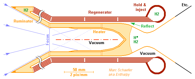
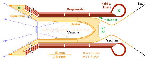
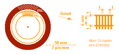
This is how the chamber could be made, I believe - new developments always bring surprises. Hot parts are of tungsten alloy. Spark machining shall make the many thin deep shapes, and an electron beam weld the parts. Click to magnify the image. and the front view: The Sun's virtual image (D=38mm, 20kW and 18MW/m2 from 4.4m concentrators) enters the heater's cavity (40mm) with 1:1.85 convergence. The heater absorbs light and transfers heat by conduction to hydrogen in channels. 63µK*m2/W through tungsten and <37µK*m2/W through hydrogen drop only 130K at the heater's beginning, with ~1.3MW/m2 absorbed there and 60% reflected. At depths where direct and reflected light have dropped, helical fins in the cavity increase the absorption, and a converging cone as well. The bottom finishes gently to heat the hydrogen with little drop. The heater's outer stern would radiate much (2800K and e~0.32) but the regenerator's inner face reflects it (a=0.02). The absorbed fraction (~1500W) pre-heat hydrogen by 520K. A ruminator surrounds the incoming light cone to absorb much of the light emitted through the cavity's inlet and transfer it to hydrogen (+1060K): of 4380W from a 40mm blackbody, an infinite cone would catch 3320W, but 340W less if truncated to D=200+38mm (sketched shorter). The nozzle's throat (22mm) and upper divergent emit >1320W light; cooling regeneratively the lower divergent would save much of it. The regenerator holds the chamber and nozzle by the less hot hydrogen inlet, and the regenerator itself holds by its cool hydrogen feed. Wall conduction (~800W at the cavity's mouth) thus pre-heats the hydrogen. Marc Schaefer, aka Enthalpy
-
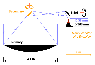
Oops. I wanted nearly parallel light converging to a small image of the Sun, and this is not compatible. A small image implies a strong convergence. Thermo's second law tells it, but knowing geometrical optics would have been even better... The good news is that a small image accepts a long path in the telescope. Just one example here, where rotating mirrors orient the thrust, and this movement adds no aberration: Stacking many mirrors in a launcher's fairing constraints such designs. And with several engines and a craft, the control must avoid collisions, as the jet impact must be hot and corrosive.
-
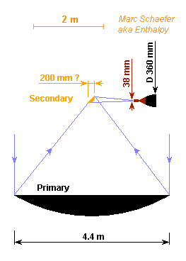
Much Sunlight power is needed, so most uses will have several concentrators as big as the launcher's fairing permits. They can consist of metallized graphite honeycomb, like usual satellite antennas. One chamber per concentrator gives redundancy and eases the orientation and the ground tests. D=4.4m provides near Earth 16.6kW if 80% are used, enough for 195mg/s hydrogen to push 2.4N. The chamber's light inlet must be small because it's hot: at D=38mm, blackbody's radiation loses 19% of the incoming power. Hence the chamber must be close enough to the primary mirror (here 0.92 diameter) that the Sun's image fits through the inlet. The small secondary mirror makes light more parallel. At D=0.2m, the temperature can be kept bearable by the reflective surface. The nozzle must be oriented, using the secondary mirror and possibly more. A different telescope formula can bring advantages, but it must keep light's path short. Marc Schaefer, aka Enthalpy
-
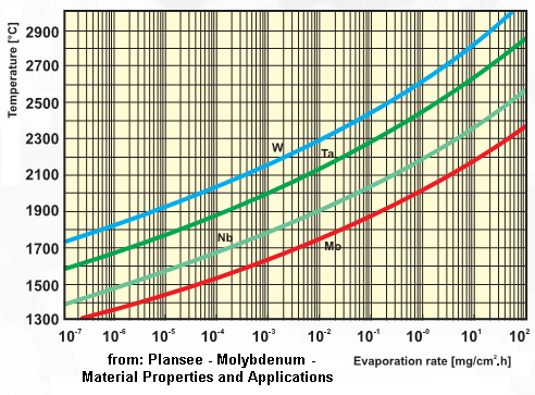
Dear visionary inventors, megalomaniac engineers and audacious explorers, Chemical rocket engines aren't up to our desire to hop in the Solar system: go quickly to Mars, deviate Earth-threatening objects, and so many more missions. We need a higher ejection speed to save propellant mass, but this takes more energy than chemical reactions bring. One possibility is to tap Sunlight instead of transporting the energy. I suggest - as others did - to directly heat the propellant with Sunlight. Converting first to electricity would enable even higher ejection speeds, but direct heating is energy-efficient, so for a long weak thrust, the collector area is feasible - smaller and of cheaper materials than Solar cells or even a heat sink. Material sublimation limits thermal designs to <3000K, so only hydrogen improves the ejection speed over a combustion. My plan is to also dissociate a part of this hydrogen to increase the ejection speed further. -------------- The heater that catches concentrated Sunlight and transfers heat to hydrogen is of tungsten alloy. At 2800K =2527°C, sublimation thins it by 45µm in 14 days, from Plansee's doc. 30mbar in the heating chamber let 23% of injected H2 split to atomic H* for performance. Expansion to 1Pa in the nozzle leaves 15.6MJ/kg from 92.8MJ/kg in the chamber, for isp = 1267s = 12.4km/s. Mean 2800K is already a lot, as sublimation is very sensitive to it. The nozzle can't grow much because the molecules' mean free path is already ~10mm. A lower chamber pressure dissociates more hydrogen and improves the ejection speed, but needs much more heating power, as the nozzle gets inefficient - recombining hydrogen is a hard task. But more pressure brings during some flight sequences more thrust traded against ejection speed: for instance, 0.8bar and 2093K from the same Sunlight concentrator and more hydrogen throughput push *2.1 times stronger with isp=800s. More to come. A former version, partially inaccurate, began there http://saposjoint.net/Forum/viewtopic.php?f=66&t=2164 and an actual version has begun there http://saposjoint.net/Forum/viewtopic.php?f=66&t=2164&p=42029#p42029 which I plan to describe more concisely in the coming few days on ScienceForums, so stay tuned! Marc Schaefer, aka Enthalpy
-
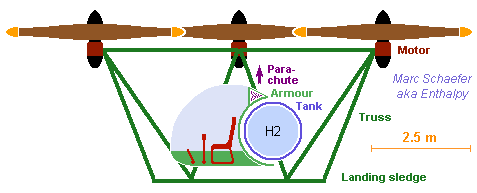
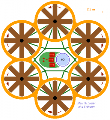
Electric motors start quickly, an advantage for an ambulance hexrotor with fuel cells. Here some figures. Three rotors at each side take length, so the body shall accommodate two beds, plus four medics and a pilot. Mass estimate: 2* 110kg - - - Patients, dress, beds 1* 100kg - - - Medical apparatus and supplies 5* 90kg - - - Four medics, one pilot, dress, seats 250kg - - - Cabin 100kg - - - Truss 50kg - - - Armour 120kg - - - Parachute 100kg - - - Infrared vision, terrain radar 6* 125kg - - - Rotors, stators, motors, electronics 6* 100kg - - - Fuel cells 200kg - - - 100kg hydrogen in tank ========== 2850kg - - - Take-off mass Six fuel cells provide more power to lift more mass with still D=3.8m rotors. The degraded mode with 4 rotors active accelerates 4*326kg/s air to 23.5m/s with 60% efficiency to lift 30.7kN or 1.1g. The degraded mode with 5 fuel cells lifts 1.1g at no cell overload. Stationary normal flight accelerates 6*254kg/s air to 18.3m/s, consuming 425kW. If flight consumes 550kW as a mean, 60% efficient fuel cells use 100kg hydrogen in 4.3h. A sketch is coming. Marc Schaefer, aka Enthalpy
-
Example of a rotating-wing craft powered by fuel cells (click for full-scale). This one has six rotors to transport three people, according to the previous message; other numbers and patterns are possible. The surrouding truss includes a landing sledge which holds the cabin by its floor. The truss has healthy angles and offers some protection to the tank and cabin. For sight, access, aspect, the truss would better lift the cabin by the top. The six rotors and the truss suggest a compact de-assembled craft, easing transport and storage. Marc Schaefer, aka Enthalpy
-
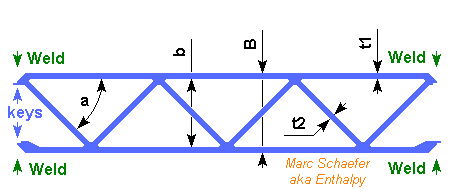
More detailed figures about a quadcopter-like with hydrogen fuel cells. 3* 100 kg - - - One pilot and two passengers, with luggage, dress, seats 3* 100 kg - - - Three Honda fuel cells of 100kW each 150 kg - - - 70kg of liquid hydrogen in one tank 6* 100 kg - - - Six rotors of D=3.8m in stators, with motors and electronics 70 kg - - - Cabin armour and floor 30 kg - - - Windshield 150 kg - - - Truss 80 kg - - - One parachute for the aircraft 40 kg - - - Shock absorbing gear 80 kg - - - Unaccounted ========== 1800 kg - - - Take-off mass --------------------------------------- Six rotors permit one to fail. The opposing one is also stopped or reduced, the remaining four get all the power and steer like a quadrotor does. Four D=3.8m 60% efficient rotors accelerate together 1046kg/s air to 18.5m/s at sea level, lifting 19400N or 1.1g. http://en.wikipedia.org/wiki/Quadrotor Stationary flight (17700N) at sea level needs six rotors (68m2) to accelerate 1213kg/s to 14.6m/s, consuming 214kW. Two fuel cells shall provide this briefly to land if the third fails. The fixed-pitch rotors can't brake a powerless fall, hence the parachute. Mean 250kW provided by 60% efficient cells consume 70kg hydrogen in 3.8h. The single tank is lighter, three would add redundancy. Panels of extruded AA5083 sandwich (t1=t2=1mm, a=45°) welded together separate the cabin from the tank (more detailed previous description http://www.scienceforums.net/topic/60359-extruded-rocket-structure/ ) More of this material makes the tank's outer shell, as I described for aeroplanes http://www.scienceforums.net/topic/73798-quick-electric-machines/#entry738806 The passengers sit at the pilot's sides just ahead of the craft's middle, exiting to the prow, and the tank and fuel cells lay just aft. Metal panels make a wall and the cabin's floor, and wrap a bit the tank below, above and at the sides, leaving much open area to the aft. --------------------------------------- For silence, each rotor has eight 1.8m long fixed blades of 0.5m chord, running at variable 3.4Hz or 40m/s. Made of foam covered with 560+300g/m2 composite, each shall weigh 3kg. The outer streamlining stators weigh each 19kg of the same material. 30°/s craft roll or pitch rate result in peak 2m/s and 43m/s2 at the blade tips. The gyroscopic moment is 81N*m peak per blade or just ~12MPa in the composite skins, and 324N*m at the shaft or just 0.15m times the lifting force. 2*15° roll or pitch in 2*0.5s need at each rotor 8.4m/s2 or 838N change over 2950N. Accelerating a rotor from 3.4Hz to 3.85Hz in 0.5s takes 245N over mean 1670N. Each fast 50kW motor and its reducing belt, plus the shaft and bearings, shall weigh 57kg. I didn't check a slow motor. Stator blades don't look so useful. --------------------------------------- A truss of AA6082 D=150mm e=1mm tubes holds the rotors together and with the cabin. The landing gear's shock absorber might use my viscoelastic elements or not http://www.scienceforums.net/topic/71234-deployment-brake/ A sketch is to come. The aircraft is a simple assembly like toy quadrotors are, but optical features suggesting a high-tech aeroplane promote passengers' confidence. Marc Schaefer, aka Enthalpy
-
Hydrogen fuel cells would bring big advantages to helicopters. Fly long! Airborne 1t including passengers and fuel takes ~100kW with 78m2 rotor(s), say mean 130kW with the manoeuvres: that's two Honda Clarity fuel cells of <100kg each. 48kg hydrogen keep it in flight for 8h - that's 100kg with the tanks I described there http://www.scienceforums.net/topic/73798-quick-electric-machines/#entry738806 Electric motors save maintenance, expensive and long with gas turbines. Electric motors are easily spread among many rotors, leading naturally to quadtoror-like designs. This is way easier than the pitch of common helicopter blades, which changes over a turn. http://en.wikipedia.org/wiki/Quadrotor Swift start and stop. Important to a businessman who pilots himself. Fuel cells bring range and flight duration that enable the classical missions of gas turbine helicopters, beyond city taxis and sightseeing tours. Electric multi-rotor copters must also be more silent and cleaner, hence better accepted. Marc Schaefer, aka Enthalpy
-
+195°C is unattainable to polypropylene and difficult for a plastic, whose cost follow closely the heat resistance. Silicone would be half-way affordable in small amounts if this rubbery material is acceptable; maybe polyoxophenylene and other technical polymers, up to polyimide, but check the cost... Matweb is a compact source of data, Goodfellow an other one. Could you take a metal or a ceramic? Pyrex for instance would be cheaper.
-
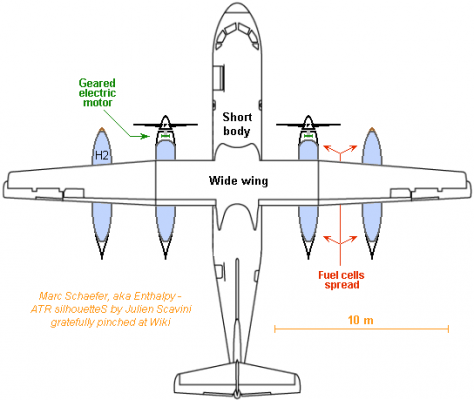
Hydrogen and fuel cells carry more energy per kg, which increases an aeroplane's range. This example combines ATR 42's short body (even the tail?) with ATR 72's wider wing to carry the <4000kg fuel cells providing 4000kW electricity. 7000km range (not the limit) at 554km/h and mean 2*1400kW with 60% *95% efficiency take only 1574kg hydrogen carried in 4 tanks under the wings. A geared motor eases the overall design. I prefer to spread the fuel cells among the tanks and distribute only electricity. In a new design, consider several bodies like Rutan's Voyager had. The chimera ATR 72-42 frame shall take-off at 22500kg but weigh 12100kg empty. Minus 4000kg fuel cells but plus 300kg from lighter electric motors leave 6700kg. Four tanks built as previously take 1484kg. Hydrogen for the full range and two pilots leave 3.4 t transport capacity. London - Dubai - Hong Kong or Tokyo - Anchorage - New York - Amsterdam at 554km/h here is too long for passengers but parcel or freight companies can like the improved flexibility or fuel savings over airliners' hold. A fast business aeroplane would also benefit from hydrogen's range. Marc Schaefer
-
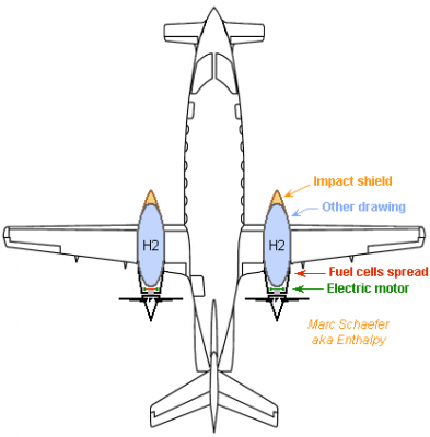
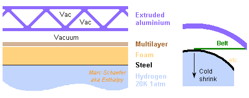
Piaggio's P180 Avanti is a business aircraft: http://en.wikipedia.org/wiki/Piaggio_P180_Avanti and it could fly right now with fuel cells: - Reported 5.3M€ price allows 2*6 fuel cells from Honda's FCX Clarity, as the whole car is said to cost ~140k$, and this saves the turbines. - 2*6 fuel cells weigh ~1000kg but replace 1200kg kerosene and 2*170kg turbines with light hydrogen and light electric motors. - No more turbine exhaust through the propeller. Swept blade tips should help as well. 2800km cruise at 644km/h and 80% power or 507kW take 2*8GJ, obtained with 60%*95% efficiency from 2*98kg hydrogen carried liquid at 1atm: the tanks are smaller, lighter and supposedly safer than for gas under pressure. Then, hydrogen fits in the volume of the original nacelles, together with the fuel cells, motors and propellers, and can be kept away from the cabin. Hydrogen takes 2*1.4m3, for instance ellipsoids 1m wide and 2.8m long. The nose fairing protects against impacts, with fibre and foam like a bulletproof vest. Adjust the center of mass by the compact fuel cells. Bigger tanks would increase the range. The neodymium electric motors (2*65kg) can drive the propellers directly, resembling the PW127M equivalent already described. Unoptimized, the gap can have 480mm diameter and 105mm length. 30 poles and square wire let lose ~6kW, maybe air-cooled at the spread half-turns of the wires. I propose to hold hydrogen liquid at 20K and 1atm in thin steel, superinsulated and hold in a vacuum vessel by polymer straps; this design may also fit cars and others. Ask your usual satellite designer, or Wiki. Here 200µm Maraging steel (11kg, per nacelle here under), coated with nickel and brazed together, resists 10bar. 30mm foam (10kg) let pass only 1.5kW if vacuum is lost. This leaves 1 hour to reach 10bar, or lets 3.4g/s evaporate. That's only half the engine's consumption, so the plane can go on flying, but it's a strong flame on the ground, so foresee a safe purge. 80 plies multilayer insulation (10kg) in vacuum let 0.6W pass through. That's 3.3kg/month evaporation, which can optionally feed a fuel cell that power a cryocooler keeping hydrogen liquid, as Nasa proposes. Polymer belts (<1kg) hold the steel envelope in all directions. Cumulated 1cm[super]2[/super] are more than enough, 10cm free length leak <0.1W. At the proper (3D!) angle, they let the steel envelope shrink unhindered. Extruded aluminium profile is welded together to constitute the vacuum vessel (74kg). Details there: http://www.scienceforums.net/topic/60359-extruded-rocket-structure/ 1mm walls (less if possible) of AA5083 for 40mm sandwich thickness resist jumping on and offer successive airtight walls. The profile can be round, maybe in the extrusion direction as well. Someone else shall design the airtight opening, preferably as lower and upper half-shells... Marc Schaefer, aka Enthalpy
-
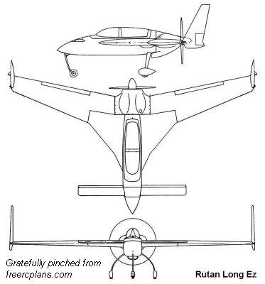
An electric motor can propel Burt Rutan's LongEZ: the "Long ESA" does it (search keywords). http://en.wikipedia.org/wiki/Rutan_Long-EZ Glider-like aircrafts like Yuneec can fly for an interesting time on battery power, but not the LongEZ meant for general aviation. A 10-week student project at the TU Delft checked hydrogen and fuel cells to supply an electric motor on LongEZ: http://www.tudelft.nl/en/study/undergraduates-bachelors/undergraduate-programmes/aerospace-engineering/degree-programme/third-year/design-synthesis-exercise/ds-exercise-2012/taking-the-next-step-towards-zero-emission-general-aviation/ with excellent flight duration and range. I wanted to check a quick electric motor, but a slow 86kW motor is light and saves the gear. To rotate at 45Hz or 36m/s, its 2mm thin Nd magnets are wrapped with little graphite; they achieve 0.89T in 1mm gap, which is 52mm long and has 260mm diameter. 28 poles contain each 3 slots, 2 being active at any time, each fitting one phase. Each slot contains 2*3 wires of 2mm*2mm, in series for a flat-top 282V drive. The 4,5% losses could improve if wanted, and the wires' spread half-turns dissipate them easily in air. The motor looks similar to the previous APU and weighs 10kg. A single Honda FCX Clarity fuel cell supplies the electricity. Does its price fit this aeroplane? Its mass, plus the motor and the inverter, replaces the original Lycoming O-235's 109kg. 3235km range at 232km/h, or 50,200s (14h!) at 34kW (40% power) need 1.85GJe. That's only 10.7kmol or 21.7kg hydrogen with a 60% efficient fuel cell. At 298K and 300b it takes 1.1m3, light with graphite composite but hard to accommodate. Liquid at 20K and 1b it takes 0.31m3, a D=0.84m sphere or ellipsoid which fits in a longer aft. More later about the insulation. Marc Schaefer, aka Enthalpy
-
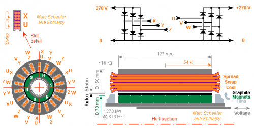
Auxiliary Power Units feed aeroplanes with electricity and traditionally compressed air when the main engines don't do it. This alternator design shall rotate at 813Hz like the gas turbine, suppressing the gear, to provide 1270kW. Click the sketch for full scale. 10m thick Nd-magnets create 0.9T at the gap. 3mm of wound graphite composite hold them at 200m/s. A single strand per output passes once at each of the 6 poles to produce flat ±136V; three 120° outputs in a hexaphased rectifier provides +270Vdc to the aeroplane (the 15kHz filter is not represented). This saves heavy power electronics. A second set of 3 phases share the slots and provides -270Vdc. Or put the second set in distinct slots, or have dodecaphased rectifiers... Six 3.5mm*3.5mm wires make the "Litz" strand. They swap their positions and the ends of the stator, where they spread to dissipate 24W per wire in a strong wind; each wire could be subdivided. The wires evacuate the heat produced at the middle, dropping 54K. Alternately, oil can remove heat at the wires' turns, or (easier to seal?) oil can flow through each wire. I evaluated ohmic losses to 7kW=0.55% with turns too short. Mass is around 16kg but without casing, cooling, shaft... Air cooling conflicts with the slot inductance, and both are marginal here. This lets the +270Vdc and -270Vdc interact if they share the slots. The flux' permanent return path at the rotor is designed too small, and a complementary plunger adjusts the flux and output voltage in real time. Marc Schaefer, aka Enthalpy
-
Some cars with piston engines have an integrated starter-generator http://en.wikipedia.org/wiki/Integrated_starter-generator_system As the name tells, this electric machine does both, and the difficulty is that it runs together with the piston engine all the time (and at the same speed), so torque is needed as a starter but the resulting big diameter results in a high linear speed after starting, when the piston engine runs fast. Imagine a D=300mm starter-generator that must survive if the engine runs at 10,000rpm: that's 157m/s, which produces a brutal centrifugal force. For them as well, winding graphite composite around permanent magnets - or possible around a squirrel cage or rotor coils - is a simple means to withstand the centrifugal force, simpler than a steel sleeve. Several turns of thin steel band, possibly as wide as the magnets or rotor, is an other one, where gluing or brazing is easier than slipping a sleeve on and can cumulate more thickness. ----- The integrated starter-generator saves a few parts; it also starts the engine quicker, easing features like the start-stop system http://en.wikipedia.org/wiki/Start-stop_system with more steps possible towards the hybrid electric vehicle http://en.wikipedia.org/wiki/Hybrid_electric_vehicle One little ambitious step I'd enjoy would replace the mechanical reverse gear by the electric motor. An other one would complement or replace the first gear with the electric motor so the car has no minimum speed in a traffic jam. Smooth control of low speed in both directions would also help to park a car. Marc Schaefer, aka Enthalpy
-
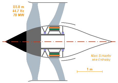
Turbofans fit faster flight, and an electric motor can rotate them too. The example shall be a Trent WXB, please: D=3.0m fan receiving 70MW at 2683rpm (taken from varied versions, hence not fully consistent). The 40mm thick neodymium magnets (here Thyssen 300/110) on OD=1.0m move at 140m/s. Thin narrow bands of permeable hard steel wrap them, totalling 7mm thickness to limit to 3mm the radius variation due to centrifugal force. The bands can be brazed (especially if covered with nickel) or glued; chemical etching can bevel their ends. The air gap is 6mm outside the magnets at idle; some elastomer or springs are required at the magnets' inner side. If feasible, pre-stressing the steel bands when winding improves that. Magnetic leaks in the bands widen the transition between the poles but loose no induction at the plateaux. The motor is 404mm long, its 16 poles have 7 active slots of 8 at any time, each 11mm wide and 44mm deep to host one phase that comprises 4 turns of square copper wire, 9mm*9mm large with a 3mm*3mm central hole. Induction at the gap is flat 1.09T, current per slot 10.1kA, the inverter's supply is 4kV. Ohmic losses total 730kW or 1%. Fe-Co laminations at 2.0T loose 70kW. 18dm3/s cooling oil flow at 5m/s in parallel through all wires, and some more through iron. The bare electric motor weighs 2030kg, a complete original Trent XWB 6600kg. The stator has OD=1.33m, or the mean diameter of the Trent's primary air inlet. Huge strong magnets are a real danger for mechanics; a squirrel cage design would improve it. Wrap the aluminium or copper cage in steel or graphite composite to resist the centrifugal force, including the shorting ends. Well, as soon as we have 70MW electricity on board... Marc Schaefer, aka Enthalpy
-
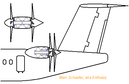
The unducted fan or propfan has two counterrotative propellers so the downstream air doesn't rotate. A bigger blade pitch then remains efficient, so the propeller can be used for faster flight. http://en.wikipedia.org/wiki/Propfan Electric motors combine with counterrotative propellers more easily than turbines do: The version at the fuselage has concentric shafts. The detached version needs the pylon between the propellers, but helps dynamic stability and the bearings; I expect propellers wider apart to be less noisy. Electric motors can have the rotor outside - not depicted here, please look at a processor cooling fan. This enables more layouts that combine well with propellers but are less favourable to the bearings nor the protection against dust and rain. Marc Schaefer, aka Enthalpy
-
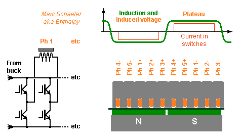
If an inverter that produces sine waveforms of MW at kHz is too difficult, I figure it can make nearly square waveforms. In that case, I'd drop the refinements that induce a quasi-sine voltage at electric machines: split coils, shared slots, variable gap... One coil per pole, one slot per pole and phase, wide magnets shall induce a nearly square voltage. Keep maybe some slot skew. Then the power components can switch once per output period to apply the rail voltage when the induced voltage has reached its plateau. During the voltage transitions, current flows through the flywheel diodes. 2 phases from 3 (or 4 from 5, or 6 from 8...) provide power at any time. The sizing advantages of three-phase current are lost, but the square waveform compensates them. Optimized timing between one phase switching off and the next switching on can reduce noise. If the slot inductance hampers the current rise, drive the switches shortly before the voltage plateau. The rail voltage must adapt to the rotation speed and the required torque - indicated by "Buck" on the sketch. At least near cruising speed, I'd synchronize the voltage regulator with the phase switches. The nearly-square induced voltage applies also - more easily - to a generator that feeds an input rectifier. Marc Schaefer, aka Enthalpy
-
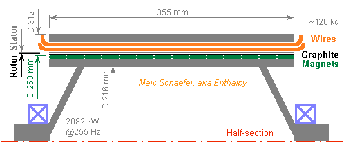
The gear can be avoided. Again 2082kW as the PW127M, but the wide ring motor rotates directly at 20Hz. At D=1000mm hence 62.8m/s, the 3mm thick Neodymium magnets (happen to be Thyssen-Krupp 340/88) need only 0.15mm graphite winding and achieve 1.02T in 1mm radius gap. With 66 poles and 132 passes 205mm long, each of the three phases gets 1726Vpk induced in the single turn. The 6mm*3mm wires get 1mm thick insulation; the slits may need some potting in addition, especially at altitude. Diameter, mass and losses can be optimized against an other. At this speed, a squirrel cage would have been possible. The present design is wider than the gas turbine but only as tall. The motor's ring weighs about 280kg alone. Its ohmic losses are 42kW or 2%, but as it saves the gear's mass, maintenance and 1.5% losses , I prefer it. Marc Schaefer, aka Enthalpy

-
Hello, heirs of James Clerk, Nikola and the others! It is well known, but by too few people : in an electric machine, only the force means losses and heavy parts, the speed comes for free. When a motor or generator runs quickly, say 50 or 100m/s at a power plant, it is smaller than a turbine. Quick machines with rotating permanent magnets use to hold them in a tight sleeve of strong steel to counter the centrifugal force. I propose to wind a composite of graphite fibres around the magnets instead of the steel sleeve. Graphite fibres are lighter than steel and produce less eddy current losses where they cross the stator's windings; better, while the accurate diameter of a steel sleeve is difficult, fibres are commonly wound tight over varied cores, even with a pre-tension useful here. A unidirectional composite looks best here, and pre-impregnated graphite is usual at wound pressure tanks for instance - other fibres may emerge. Some thin elastic material below the magnets can prevent cracks. To run at 200m/s, 5mm thick magnets weighing 7500kg/m3 need 1.5mm of graphite composite withstanding 1000MPa - or scale both thicknesses. Neodymium magnets like Thyssen-Krupp's 300/110 still achieve 0.78T through the graphite plus 1.5mm radial gap. I already described a small electric motor turning a rocket engine pump, there http://www.scienceforums.net/topic/73571-rocket-engine-with-electric-pumps/#entry734225 and http://saposjoint.net/Forum/viewtopic.php?f=66&t=2272&start=80#p41298 the following one outputs 2083kW like the PW127M gas turbine that moves the ATR-72 and other successful planes. http://www.pwc.ca/en/engines/pw127m http://de.wikipedia.org/wiki/Pratt_%26_Whitney_Canada_PW100 http://en.wikipedia.org/wiki/ATR_72 The motor rotates at 255Hz, so a gear drives the propeller at 20Hz - but a turbofan would need none. 5mm thick magnets at D=250mm run at 200m/s. The 355mm long stator has 3 phases and 18 poles. The windings are one turn of square 5mm*5mm copper that makes 36 passes through the shared 54 slits. The induced coil voltage is 1726Vpk (reduce the length if I botched a cos30°...) and the current 804Apk, nice for an inverter supplied with 3kVdc maximum. Coil resistance is 13mohm (or a bit more as the skin depth is 1.4mm at 2292Hz) so ohmic losses are 13kW or 0.6%; core losses are small with the proper material. This electric motor weighs ~120kg, is ~400mm long and 312mm wide , while the PW127M is 660mm wide and ~1.2m long without the gear, and weighs 481kg with the gear. Direct retrofit, though we still lack proper fuel cells. Marc Schaefer, aka Enthalpy
-
In order to offer Fresh the opportunity of a class-action. But for that, he needs some credible story and can't find it by himself.
-
Interesting! Carbon fibres are anyway the material of choice to make strong, stiff and light. Aluminium extrusion has the advantage of classical low-tech. Cheap investment, since extrusion on demand can even be contracted to a supplier, and welding needs a machine meanwhile banal. Carbon fibres were proposed by MAN GmbH to replace a difficult steel process for the casings of Ariane V's solid boosters. Presently, forged rings of austenitic steel are brutally cold-rolled on a specially-made machine to make high-strength thinner cylinders whose welded ends are thicker. Carbon spinning would have been cheaper and lighter, but wasn't accepted for Ariane V. It's used on Vega now and was already common on high-pressure liquid tanks that transmitted no thrust. Then, one has to check if the desired shape and strength can be achieved: fibres work best if spun, and aligned in the stress directions, up to the locations where forces apply. Easy for a pressure vessel, less so for a tank with moderate pressure but compressive axial load. Here stiffness demands a non-uniform thickness, or hollow materials. This is the reason for the sandwich walls and rods described here on 29 December 2012. If the new laser process can help it, it's of course highly welcome!
-
Von Braun used internal truss when he was young. It would still work, but there are limits: - A strong skin is nice to fly quickly through air. To resist impacts of rain, birds, chunks of ice detaching from the cold tanks... And to avoid air flow instabilities at the skin. It's already few mm thin, saving more is difficult. - A tank must be pushed at its base, over the whole lower head. This combines less well with a thrust concentrated in a truss. - The truss and the skin must have the same temperature at every time. Nothing damning, but one difficulty more. What does exist: upper stages (modern Centaur) that are fully enclosed in the payload's fairing at low altitude. They have an external truss, and the tanks are ultra-thin "balloon tanks" of best steel, enough to hold the small pressure but not transmit any thrust. The combination is light. The older Centaur described there http://en.wikipedia.org/wiki/Centaur_(rocket_stage) stands up thanks to internal pressure; this risky design is oldfashioned now. On a lower stage, I considered a structural oxygen tank surrounded by balloon hydrogen tanks that lift nothing beyond their contents, but frankly, I dislike such thin skins exposed to the wind. With extruded aluminium I regularly compute 30-40kg/t with hydrogen+oxygen, already excellent, and with outstanding stiffness and resistance.
-
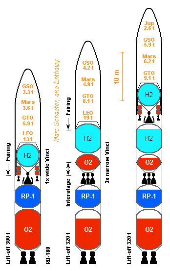
Light tanks and good engines go to geosynchroneous orbit in just two stages (click the drawing to magnify). Walls are of aluminium extrusion, with a=45° and the extrusion horizontal. Magnesium would improve. At the one-Vinci stage, the long engine shall weigh 400kg, adapters 200kg, avionics 200kg, and the supported balloon tanks 40kg per ton of propellants. Notice the fairing covers them. The roll and injection verniers get hydrogen and oxygen at 1.5b from the tanks, burn them at 1.0b and expand to D=0.3m to achieve 4*500N and 376s, losing no efficiency and adding just 20kg. Nearly the ones from DLR. The empty stage carries 21.5t of propellants and weighs 1680kg. Maybe an ESC-B. ---------- At the three-Vinci stage, the short engine shall weigh 300kg. Four or six chambers could in the future share one bigger turbopump and one set of actuators. The walls (1595kg) have B=19mm t1=t2=1.5mm of AA6005A, the dropped interstage (727kg) as well. Hydrogen heads (195kg) are 1mm AA7022 ellipsoids with 2r=3.6m. The oxygen tank (205kg) is an ellipsoid (2R=4.8m, 2r=3.4m) of AA7022, top 1mm and bottom 1.5mm. It holds at the wall by two cones (61kg) of 1mm AA7022. A truss (45kg) of AA7022 tubes holds the engines to the cone - or maybe to the walls. Foam weighs 72kg. Carbon and ultra-thin steel may save mass, but aluminium is cheap and sound. Everything can be welded here. Oxygen above hydrogen might have saved wall mass as the fairing would cover it. The supported tanks weigh 2173kg and carry 53.8t of propellants, or 40kg/t. The stage weighs 3273kg empty, or 61kg/t. ---------- At the RD-180 stage, the oxygen walls (1752kg) have t1=t2=2mm of AA6082, others (1994kg) have B=19mm t1=t2=1.5mm of AA6005A to resist 6MN*m bending plus a factor of 1.5. Heads (652kg total) are ellipsoids (2R=5.4m, 2r=3.6m), 2mm of AA7022 below the oxygen, 1.5mm elsewhere. The structural walls and tanks carry 259t and weigh 4437kg or 17kg/t. The engine (5850kg), its truss (230kg) and foam (39kg) bring the empty stage to 11.1t or 43kg/t. The fairing (3400kg) is dropped with the first stage in the performance evaluation. Aluminium extrusion that light would have needed t1=t2=1mm, so this is probably standard composite. If an RD-180 equivalent is designed, it could usefully throttle more deeply, have wider nozzles, burn Pmdeta or Farnesane, have a turbine and gas generator of molybdenum. Marc Schaefer, aka Enthalpy

-
ONE message before, LAST paragraph: "The gained stiffness enables tubes much voider than a bare skin or even a simple sandwich allow."
-
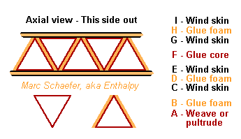
"I can tell you building costs go way up and people have to be trained and cert in working with mag. I doubt you will find any welders cert. and you will need clean air welding mask I am sure by osha. You might require semiannual blood tests as well." => Up to now you can copy-paste text from the Net. By the way, this seam length would be made by a machine, just as for aluminium tanks. This should be clear to everyone who has welding experience and has already seen a full-size rocket. "I have a block of mag with a flint on it in my first aid kit. You shave some with a knife and use the flint and it goes up quit nice." => And the block does not catch fire. You can do the same with a block of iron and a grinding wheel. ==================================================== Beyond magnesium extrusion, an additional possiblity would be pultrusion. Some companies claim to include long carbon fabric in the profile pultruded through the matrix. This would make the walls stiffer, stronger and lighter than aluminium and magnesium - provided, of course, that the profile show a reliable behaviour. Assembling them into a tank wall or interstage section required generous overlap of the fabric. Or is it better to weave or pultrude the hollow profiles making a core and wind the inner and outer sheets of a hollow wall? Triangular profiles can be woven and constitute the core's zigzag, possibly with a foam layer between them. I doubt a lighter tank obtained this way makes a launcher cheaper than metal extrusion does... An extruding machine costs around 100k€ and produces easily one launcher a month; many heads in parallel can make the weld joints. Marc Schaefer, aka Enthalpy ==================================================== This is how I imagine a hollow wall of composite material if not pultruded at once but assembled, with a core of elements woven or pultruded in advance: Here the core walls can be a sandwich with foam (the skins as well), which allow them to be much thicker than a honeycomb yet strong. I've sketched one layer of prisms, but there could be more. Foam between the prisms is what prevents delamination... But tension in the outer skin, resulting from the winding process, can help. A syntactic foam is heavier but stronger than PU foam. Maybe the foam can be pultruded with the prism at once. With carbon fibre for instance, the wall must be nicely stiff. At a rocket tank, the inner skin would probably hold the pressure and the other ones give stiffness. To make a single-stage-to-orbit or an upper stage, the effort could pay. A flat panel would have skins laid of fabric or crossed monodimensional prepreg, rather than wound. Not sure how new this is... Omega stiffeners are well known, maybe the foam is new. Marc Schaefer, aka Enthalpy ==================================================== About the same assembling method can produce tubes, with a core composed of prisms made in advance, and skins wound or woven around, possibly with foam layers: The gained stiffness enables tubes much voider than a bare skin or even a simple sandwich allow. I've sketched six prisms, but more layers and other angles are possible (and more meaningful). Could be nice for the masts of a Solar sail, the external truss of a rocket with balloon tanks... Marc Schaefer, aka Enthalpy