Enthalpy
-
Posts
3887 -
Joined
-
Last visited
-
Days Won
1
Content Type
Profiles
Forums
Events
Everything posted by Enthalpy
-
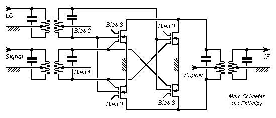
With valves as with Jfet, symmetric preamplifiers were built to improve linearity at receiver input. I don't understand the benefit, since this reduces only the even nonlinearity which isn't a big drawback at a preamplifier, where transmodulation results from odd distortion. In case I got it wrongly, the matched pair of multigate transistors would be usable as a preamplifier as well. A high impedance shared by the sources of transistors working symmetrically reduces further the even nonlinearity. Multigate transistors are more stable here as well. The impedance can be a coil, a resistor, a current source if not capacitive... this latter being more likely if integrated in the same chip as the HF transistors. This can be interesting for an odd frequency multiplier, and also for the doubly balanced mixer with four transistors sketched above (not for the two-transistors mixer), where all four sources can be tied together (possibly through capacitors) to share a common constant current, say from current source(s). It would linearize further the circuit, improving the intermodulation behaviour at the signal input. Marc Schaefer, aka Enthalpy
-
This must be a lab, not an industrial plant.
-
Scientific Difference Between Petroleum & Natural Gas
Enthalpy replied to Tahir's topic in Organic Chemistry
Petroleum reservoirs are always topped by natural gas. Enough gas is desired to let the oil erupt from the drilling without a pump. The vastly main constituent of natural gas, methane, is little soluble in petroleum, so this one is easy to distinguish. Ethane is essentially present in gas as well. The transition is at C3 and C4 which are present in both gas and oil and are commercially extracted from both (propane, butane, LPG and other names). C5 and up are essentially oil constituents. So: the limit is a bit fuzzy. We call gas what is harvested gaseous and oil the liquid, but a fraction is common to both. -
Single wires without an iron core produce an induction too small for a hard disk drive. Or it needs >10kA at 10mm of the magnet - this is how magnets are made. The biggest current in a PC feeds the CPU core, it's slightly over 100A. Hard disk drives are not shielded. Aluminium foundry and sheet.
-
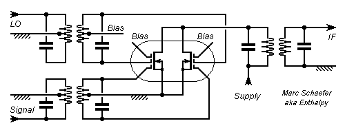
The doubly balanced mixer has gotten a half-way legible diagram; click to enlarge. The cabling mess better happens within the chip that carries the matched transistors, like in the old SO42. Replace the MOS by other multi-gate FET as you like. The third gate saves some power from the local oscillator if the intermediate frequency doesn't differ much; its bias acts on intermodulation. Marc Schaefer, aka Enthalpy

-
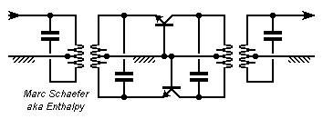
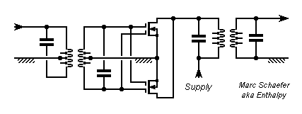
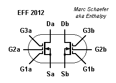
Greetings to all HF enthusiasts! This shall be a frequency multiplier, but beware I haven't tested it (and won't in a foreseeable future). It will multiply, but whether it improves over existing diagrams remains to be seen. This diagram is to harvest an odd harmonic; connect the collectors together at one end of the coil to harvest an even harmonic. A balanced mixer could be built similar to the multiplier, with the LO input between the input secondary's middle point and the ground; adding two PNP would make a doubly-balanced mixer. I doubt such a mixer has advantages over a diode bridge. ----- Unusually, the multiplier has bipolars in common base without a power supply. All power comes from the input signal. The bipolars conduct at some 0.7V input voltage but drop only about 0.4V; this behaviour is more brutal than a diode, and shall transfer a bigger proportion of the input power more concentrated in the harmonics, so I hope losses are reduced as compared with a diode frequency multiplier; The emitter current determines essentially the collector current, so imbalances between the transistors are less important than with the traditional two-transitors multiplier; operation nearer to Ft improve as well; The output power is well defined and should depend less on the input power than with diodes or traditional transistor diagrams. Feel free to match the transistors by Vbe, Ft, capacitance... or use a matched pair in a case. I estimate that the fully balanced connection of the transformers, with a cold point at the middle, brings more to an odd-only or even-only output spectrum. Stability isn't guaranteed, as the input signal brings power to the circuit. Beware many recent bipolars accept only a common-emitter configuration. I'd take only the necessary Ft, and wouldn't put the output tuning capacitor near to the collectors. Marc Schaefer, aka Enthalpy ================================================= This one relies on the ability of either gate of a tetrode MOS to pinch the drain current, which here passes by zero twice in an input period. Beware again, I haven't tested this circuit. It is meant for even multiplication only. Because the two gates aren't identical, I've put two transistors in a symmetrical circuit to minimize the odd harmonics. Injecting the signal in the upper gate isn't perfect for gain nor stability. A cascode would improve that, possibly shared by both tetrodes, using a bipolar if stable in common base, a single gate HF MOS if you find one, or a dual gate MOS. Bias as normally the second gate would be. Especially then, the multiplier would accept a small input power. Feel free to add in each source a capacitor and a resistor, or much better, a precisely matched integrated current source. This is interesting with other diagrams as well. Replace the MOS by MESFET, HEMT and other variants ad libitum. Marc Schaefer, aka Enthalpy ================================================= The second frequency multiplier would ideally use a matched double pentode component, still to be made, like this: The third gate would make the cascode without cabling penalty. Two transistor on one chip would be matched by fabrication. Or even, have four transistors cabled internally in pairs in a cross pattern, as in op amps, if this improves further. MESFET, HEMT and the like can improve over MOS. Maybe these component and circuit will be used first as part of a more complex integrated circuit and be made available later just as a matched pair. I have found no use whatsoever for a filament, alas. Marc Schaefer, aka Enthalpy ================================================= The same matched double pentode would make a nice mixer. Tetrode MOS are already excellent mixers, whose intermodulation is second to diode rings only, provide gain instead of loss hence noise, and need little LO power. A symmetric circuit can only improve intermodulation. Whether the local oscillator best drives the gates 1 or 2 against intermodulation is unclear; against injection, gates 2 are better. Bias should also be optimised against intermodulation. Again, the sources may have a capacitor and a resistor or a current source. In fact, an even more symmetric circuit would be even better. Put four transistors on a single chip, and at one pair, swap the inputs of either the signal or the local oscillator; bring the new drains to the opposite end of the now symmetric output transformer. Best described with words, as the diagram is a mess. Refer to the SO42's input swaps if you wish. Maybe the four transistors in cross pattern suffice to compensate all linear geometric gradients in the production process; cable 16 transistors on the chip if not. In any case, I wish that such a mixer component remain usable as a frequency multiplier as well. Here also, MESFET, HEMT and the like can replace MOS. Low-capacitance outputs should be preserved, as the output signal is fast at some uses. Marc Schaefer, aka Enthalpy

-
This is a known relation in accelerometers. In the second figure, the deflection L does result from the weight, and then the resonant frequency can be written this way as a function of the deflection instead of the spring stiffness. At accelerometers, it's used as a sensitivity figure (in terms of displacement) related to the resonance frequency.
-
It can do both, for instance in H2.
-
Even without a camera I could read you at normal character size.
-
E=h*F is for a photon of positive energy and real wave number. Nothing difficult. It's just that once you've said "virtual photon" you've made an analogy with other particles, but it brings little more.
-
This will not happen. One reason is that molecules change their speed all the time. At every shock, which happen in a liquid in less than one molecule length.
-
Is a permanent deformation acceptable? If not, only hardness help. Some amorphous metals, including magnetic materials, have 3500MPa yield strength and virtually no elongation at break, just like some tool steels, but this limits the elastic asymmetric impact speed to 80m/s, far from Mach 3.
-
what is volume of liquid in partially filled cylinder
Enthalpy replied to Mr. Khan's topic in Engineering
Your cylinder is horizontal in this formula. Forget A*h here, it's A*L. h is the liquid's depth (from the bottom or from the center?). The simplest method is to compute the angle resulting from h/R, the area of the disk's sector, the area of the triangle that completes the sector, then add and convert everything into h and R if you feel it simpler than the angle - that's rather a complication. -
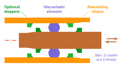
Hello everybody! I imagined and prototyped this brake long ago for the deployment mechanisms of a satellite I never built. In essence, it's clean, it can work in vacuum and in a wide temperature range, and it can wait for long without maintenance, so other uses must be possible, like semiconductor, food, optics processing... It compresses a viscoelastic element and lets it roll to brake the relative movement of two parts, so that an alternate deformation results and dissipates energy. My viscoelastic element was a seal ring and the other parts were cylindrical - but feel free to make them flat or elliptic if it brings anything. Two gentle slopes help a lot inserting the ring. Repetitive operation would demand stoppers, whose shape is simplified on the sketch, as the rolling surface is better smooth right from the slope. The braking resistance is difficult to predict unless you have a software for viscoelasticity and know the material's properties at varied frequencies, temperatures and stress... Even then, experimental verification remains necessary, so you can just skip the simulation step. The braking resistance increases with compression and scales as the dimensions squared. The initial orientation of the ring is almost unperceivable, but after hours, the elastomer creeps and makes one position more stable. With the material I had (NBR?) this was important but didn't prevent movement under the expected force. Whether some material can damp at 10Hz but creep little over weeks is unclear. Varied elastomers are used for seal rings, and all elastomers dampen except natural rubber. Silicone and Viton fit secondary vacuum and dampen a lot over varied temperatures. Creeping and limited friction are a drawback for Viton. The "viscoelastic properties" and "complex shear modulus" (search keywords) depend on the precise material including its molecular weight and cross-linking, which define the relation between temperature, frequency and the complex modulus, so "polybutadiene" or "polyurethane" is too imprecise. The imaginary part of the shear modulus must increase with frequency over the whole desired temperature range, so the braking force increases with velocity and can stabilize the movement's speed. It's usually given at zero compression, alas. My rod and tube were of POM-H. Examples of clean materials with great friction are nickel layers, anodization layers on aluminium, titanium, stainless steel, ceramic layers... but most bare metals and plastics seem to suffice. Two viscoelastic elements in a brake help keep the moving elements parallel. Marc Schaefer, aka Enthalpy

-
Materials that survive to shocks? It was part of a former job, and past 30m/s it became difficult. I'd say 100m/s is a limit under extremely (=impractical) conditions on the shape of the object. Just brittle alloys, as hard as possible, are a good choice to survive a shock repetitively - say, tooling steel. The parts must be designed so the shock wave stays below the yield strength, not trivial at all. Soft materials are better against a single shock, but as they deform at each shock, they get unusable. An other possibility is a damping material, that dissipates the mechanical energy but regains its shape... more or less, and after some time. This materials are difficult to use because they creep, but just polyurethane is an excellent candidate (the best one). Though, at 120km/s and not Mach 3, I've seen many PU parts fail. Also, they're hard to predict by computation.
-
Land surface temperature (LST) as earthquake precursor
Enthalpy replied to Ardit's topic in Earth Science
You can eliminate heat produced by radioactivity, since inhabitants would be dead by radiation well before any temperature increase can be sensed. -
Acetylene is known to detonate by decomposition, including without oxygen. Pressure is a known factor, heat an other, many banal metals also - they act as a catalyst. You could see the MSDS. Not only acetylene: all small acetylenic molecules behave this way. Including Propyne, which a rocket design hobbyist tries to advocate as a propellant. It's the reason why acetylene for torches is kept dissolved in acetone, instead of just compressed in the bottle as is done with other gases like propane, oxygen... A Russian team (at a very reknown manufacturer) presently tries to develop a rocket engine that burns an ammonia-acetylene mix. I hope this bizarre attempt did not result from any of my ideas. Both ammonia and acetylene are far too dangerous to store and use in 100 or 1000t amounts in a rocket.
-
Consequently, I won't read it.
-
The power used by a fish is hard to evaluate and this has led to many wrong conclusions. One example is the corrugated skin supposed to improve the water flow. For long also, the speed of sharks and swordfish was wrongly reported as unexplainable. Caudal propulsion has advantages: - It doesn't catch algae as easily as a propeller - It can be bigger than a propeller, hence potentially more efficient, by taking more water and accelerating it less - More subtle, it can be more effective at limiting the tip vortices. That is, an upward part of the tail can accelerate water downward and inevitably to one side, but a downward part of the tail can keep or improve the water's downward speed and a the same time brake its side motion. This saves power from unnecessary lateral speed and the associated vortices. A propeller could do nearly the same... It would need to be enclose in a cylindre and be followed by stator blades that elimiante the unnecessary water rotation. Not done because all these steps introduce their own losses and complexity. Also: once the side speed is reduced or suppressed, the tail doesn't need to move laterally much faster than the water does to the aft - a propeller need to so it produces downward speed rather than rotation speed in water. The slower tail is a big advantage to avoid cavitation. This would be one more benefit to boats if they adopted caudal propulsion.
-
The frequency is zero, and the virtual photons are the field, whose force you feel when holding two magnets.
-
How can we transmit the electricity with out a wire
Enthalpy replied to alwaysdoubt's topic in Physics
It's done commonly. -
Microwaves can carry any power... It's limited by - The availability and price of the source. Magnetrons for ovens deliver 300W at 2.45GHz for some $ and can be summed. Expensive sources achieve MW. - The protection of people, animals, plants... - Real physical limits like air ionization wont' be attained easily in open space. It was attained in the waveguide feeding radar antennas, with several MW in few cm2, where dry nitrogen at high pressure improves over air. 170m above the source: that's a matter of diffraction "only", that is, of wavelength and antenna diameter, and of how concentrated the focus must be. Have a look at "diffraction" for lenses or telescope mirrors or antennas; the likely answer is "antenna too big for your taste".
-
Materiel that contracts or expands when electricity is introduced?
Enthalpy replied to a topic in Applied Chemistry
It's done currently with shape memory alloy (like Ni-Ti). Wires of such materials heat when a current passes, and the lengths changes - much more so than by thermal expansion alone. -
Are high efficiency indandescent lights possible?
Enthalpy replied to Anders Hoveland's topic in Quantum Theory
A few ceramics do exist with a melting point that exceeds tungsten. Unfortunately, the limitig parameter is the vapour pressure at some 3300K, which defines the evaporation speed of the emitting part hence its lifetime, and tungsten is the best choice for that. Rhenium would be about as good but more exepensive, and other elements and compounds less good, especially graphite. Sadly, this doesn't suffice to produce Sun-like light (6000K). Most methods trying to catch the evaporated tungsten (or replacement) for reuse have the drawback of catching the emitted light as well. Halogen is one method that works. Thicker filaments, resulting from a lower supply voltage, are one other, often combined with halogen. I searched in this direction for a rocket engine that heats pure hydrogen using Sunlight, and couldn't find a better material than tungsten. -
See the keel or centerboard I sketched here in the message on 4 June 2012? The swept shape is meant to ease or avoid cavitation while the fastening aft of the trailing edge shall avoid ventilation - more so if the "leg" is swept as well. This can be used as a hydrofoil as well, both for a sail or engine boat. It goes without saying, but maybe better if I say it. Marc Schaefer, aka Enthalpy