Enthalpy
Senior Members
-
Joined
-
Last visited
Everything posted by Enthalpy
-
Ox1111, why shouldn't you try by yourself before spreading the legend of burning magnesium? I wrote "I did try". What sort of value should have any text copied from people who didn't? For your information, iron, aluminium, titanium burn more easily than magnesium - if in powder form, just like magnesium. This has nothing to do with alloying. I had to use a blowtorch and melt the magnesium ingot before it caught fire if fed with oxygen. Without oxygen it went out spontaneously. That's fact. Ah, and flashes were made of zirconium.
-
A sketch representing an extrusion section is on page 1. Strength is needed before lift-off. Magnesium is not flammable. I tried.
-
Thanks for your interest! The extrusion comprises aluminium ribs betwen the inner and outer skins, all in one piece. These ribs conduct heat far better than the foam brought outside the tank to insulate it if the tank contains a cold propellant, so both skins will have the same temperature without additional measures. Very few tanks have been stabilised by internal pressure, the older Centaur stage being the classical example; safety of ground operations lets designers stay away from that. You don't really want your rocket to collapse when emptying a lower tank - nor even if the tank empties through a leak. Personnally, I'd accept a balloon tank only if it carries nothing but itself. Nearly all other stages have stiffening ribs (or integral stiffeners, or Isogrid) machined with great effort in the sheets that constitute the tanks, precisely to stiffen the walls and let them resist buckling. This is the aim of my extruded structure: provide stiff yet light plates for tank walls, interstages and fairings, that need less effort to produce than an isogrid or an assembled skin. Maybe magnesium alloys can be extruded? Less dense but thicker material would resist buckling better despite the lower modulus. If some alloy permits thin extrusions, this would enable even lighter tanks. Marc Schaefer, aka Enthalpy
-
Panels extruded the same way and welded can make payload fairings. Reasonably light: AA6005 with t1=t2=1mm would weigh some 3t for D=5m and h=10m. To my eyes, such a fairing is low-tech and looks easier to make than with composites. It should be stiffer. It won't dissipate any acoustic power as is, but its stiffness may provide a good sound barrier. Add foam? Marc Schaefer, aka Enthalpy
-
Guys, peroxide is dangerous. At 20% concentration it's bad for your skin. At 70% concentration it's a brutal explosive, quite unpredictable, and it lights most materials like gloves and clothes. Do NOT concentrate it by distillation, as you're likely to let it detonate. People telling "90% by freezing" didn't try by themselves. There is a eutectic that prevents reaching this concentration.
-
Because of RoHS law, we must use a **** solder that doesn't solder anything, despite nobody will churn an electronic card... But mercury is used increasingly in power-saving lamps, and you'll inhale it if you break the lamp. Semiconductor industry... uses really nasty chemicals, HF not being the worst! Not even hydrazine is the worst there.
-
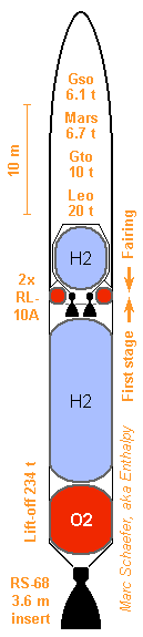
As one some Centaur stages, the fairing covers the second stage here, gaining some 700kg skin mass for the payload. The first stage extends to the upper oxygen tank, as the smaller RL-10A need no interstage that separates sidewards. (Click the image for full size) The first stage is like the Ssto, only a bit smaller. At the second stage, the tanks of 160µm steel weigh 147 and 119kg. 100kg of steel or aramide bands hold them to a truss made of AA7022 plain tubes weighing 200kg that holds the oxygen tank, the payload, the hydrogen tank and the engines. A 160kg adapter links with the first stage and the fairing. The tanks and the structure weigh 21kg per ton of propellants. This design puts a payload in geosynchroneous orbit (Gso) in two stages with little inert mass, and its payload fraction to low-Earth orbit (Leo) is outstanding. Marc Schaefer, aka Enthalpy

-
This design of an RS-68 pushed SSTO has masses and volumes similar to the other, but doesn't expose balloon tanks outside: Skin is of AA6082 with t1 = t2 = 1mm a = 45°; extrusion direction is horizontal at the hydrogen tank and vertical at the oxygen tank. Hydrogen tank heads are of 1.2mm thin AA7022. The left design holds oxygen in a Maraging balloon tank, 340µm thin, so the extrusion doesn't feel oxygen's hydrostatic pressure. The righ design holds oxygen in the aluminium skin. The top head is as for hydrogen, while the bottom is thicker AA7022 with stiffeners. Here the engine pushes the bottom directly. To resist pressure, the skin is wrapped in glued AA7075 band, nearly horizontal, the layers totalling 2.0mm at the top and 2.5mm at the bottom. Other wrapping materials would save some weight. Cold-rolled austenitic steel matches aluminium's CTE less badly than Maraging does. More than with aluminium band, pre-tension would be necessary when wrapping, to avoid worries when the extrusion is cold, and to keep the extrusion below its proof stress under pressure. Windings of fibre with polymer matrix would be even stronger but their CTE uses to be even lower. Marc Schaefer, aka Enthalpy
-
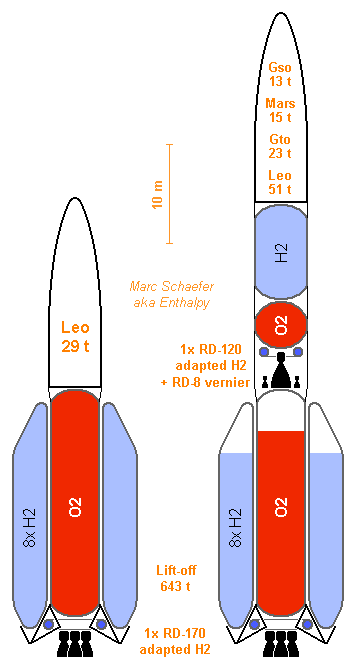
Lighter tanks make hydrogen's volume more acceptable. Their combination outperform solids to provide twice Ariane V's payload with similar mass and size, and go to geosynchronous orbit (Gso) efficiently with two stages, or to low-Earth-orbit (Leo) with one: (Click to magnify) I explained there how I hope to adapt the RD-170 to hydrogen with limited effort: http://www.sciencefo...gen-or-methane/ http://saposjoint.ne...start=40#p33663 (more detailed) to obtain from it 8.2MN and 3727m/s at sea level and 4023m/s in vacuum. The same way, Zenit's RD-120 shall burn hydrogen to produce 752kN and 4301m/s in vacuum - estimated from less detailed engine data. Alternately, the RD-180 and RD-0124, converted to hydrogen, would cut all masses by 2, which can better fit customers' needs. To reach efficiently Jupiter and beyond, add an RD-0146 stage. The RD-170 stage burns 499t of propellants - but 583t if it's alone, provided one wants bigger tanks just for that case. AA7022 extruded transversally with t1=2.7mm t2=2mm a=45° carries the oxygen and transmits the thrust; with heads and foam, this tank weighs 9.1t. Eight balloon side tanks carry hydrogen. Of 330µm Maraging steel, they weigh 6.5t together with the foam. The truss linking the engine and the tanks shall weigh 1t, but as aerodynamic lift is the main stresson hydrogen tanks, the truss won't look as I sketched. The 16.6t tanks weigh only 28kg per ton of propellants. A stacked design (D=8.4) would weigh 19.2 or 33kg per ton, marginally less than the Shutlle's external tank. The RD-170 weighs 10.8t, including 1.3t for hydrogen adaptation, and the interstage 2.0t, putting the stage dry mass at 29.4t. The RD-120 stage burns 94.9t. Its walls are of extruded AA6082 with t1 = t2 = 1mm, a = 45° and weigh 2.7t with the heads of the hydrogen section and the foam. The extrusion direction is axial below the hydrogen tank, transversal there and above. The oxygen tank is an elliptical balloon of 320µm thin Maraging steel, weighing 240kg with foam. Pressure doesn't push the extruded walls to the side. The tiny kerosene tanks supplies the pre-chamber and the vernier RD-8; together with a truss to hold the engine, they weigh 0.2t. Together, the tanks and skin (which resists up to 40% of the first stage's thrust) weigh 33kg per ton of propellants. Adapted to hydrogen, the RD-120 shall weigh 1.6t, and the untouched RD-8 0.1t. Electronics and payload adapters are granted 3.7t, putting the dry stage at 6.3t. Marc Schaefer, aka Enthalpy ================================================================== By the way, I had tried before to have a balloon tank hold the propellant's pressure, within a lighter skin that withstands only the other stresses. Before this small elliptic tank, minimal thickness at extrusions made it less interesting. But at big launchers, maybe. Like the SLS. Or if thinner extrusions can be made. Rocket technology could let extrusion improve. A machine is cheap, even tailor-made. Also, a few companies claim they extrude magnesium alloys. A mainly cylindrical balloon might be pushed by metal or fibre belts passing below and around it. Insulation foam would probably reside between the balloon and the structural wall. Less than obvious: clearance is not desired, but the balloon's diameter changes with temperature and pressure. Of course, balloon tanks can combine with a separate structural truss, where a structural wall is too heavy, as indicated at Saposjoint.net about SSTO. And aluminium extrusion makes nice struts for the truss: sounder, and easier to assemble than carbon composite. If needed, a windshield can hold on the truss, or the fairing can cover the stage(s) in addition to the payload: exists already for Centaur upper stages. Marc Schaefer, aka Enthalpy

-
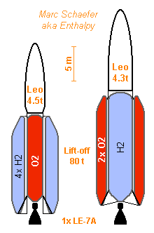
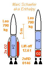
Yes, many machines exist with surprising abilities. For instance roll mills can produce zigzag sheets http://en.wikipedia....metalworking%29 But what I like extrusion to produce closed profiles, with an inner and an outer skin in one operation, with no seams that are harder to make later and less reliable. ================================================================== Here examples using the LE-7A hydrogen engine. Its D=1.815m nozzle gives 4315m/s specific impulse; a wider one may pay for its mass. With a restraint insert during lift-off, it pushes 1.02MN and brings 8763kg to Low-Earth-Orbit, minus 1832kg for the engine. The left design has a central oxygen tank of aluminium 6082, extruded in the transverse direction, with t1 = t2 = 1mm and a= 45°, which weighs 952kg with foam. Hydrogen fits in lateral balloon tanks of 180µm thin Maraging steel; four weigh 700kg with foam. A few rods weigh 200kg: this leaves 5070kg for the electronics, the adapters, and the payload of about 4.5t. Maraging sheet is hot-rolled, that's easier than cold-rolling austenitic stainless steel, and Maraging retains its strength at weld seams. A hypothetical alternative would let braze the thin sheets; stainless steel would require a coating for that, like nickel. The right design puts its hydrogen in the central tank. Here AA6005 is extruded in the transverse direction, with t1 = t2 =0.8mm and a = 45° (one extrusion company claims 0.25mm thickness is possible - this must use the weaker AA6063). This tank weighs 1500kg with foam. Oxygen fits in tanks of 300µm Maraging steel; only two pieces with foam weigh 416kg. A bit heavier, but the tanks are stronger and leave two free angles to jettison the fairing halves. 4.5t in LEO fits existing payloads. The J-2X engine may be cheaper with similar performance, but is heavier and requires a separate roll actuator; two J-2X could be more expensive than one RS-68. Marc Schaefer, aka Enthalpy ================================================================== Two RD-0146 make a tiny-cute SSTO launcher. Their D=1.25m nozzle option brings 4540m/s specific impulse in vacuum but demands a restraint insert at low altitude, pushing there 80kN each. They leave 1660kg in orbit and weigh 261kg each. The central tank relies on the ability to extrude AA6005 to t1 = t2 = 0.4mm; at least AA6063 allows 0.25mm. a = 45°, extrusion in the transversal direction. On the left design, the central hydrogen tank weighs 198kg with its heads and foam. The two balloon side tanks made of 120µm Maraging steel weigh 52kg with foam. The struts (AA7022 here, maybe graphite) add 11kg. This leaves 877kg for the electronics, adapters, and the payload of about 0.79t. The right design stacks the tanks, with t1 = t2 = 0.5mm at the oxygen tank only. This leaves only 0.7t payload. The RD-0146 and others are children of the RL10 ancestor. The RL-10A brings slightly less performance but may be cheaper. The LE-5B makes a bigger launcher and payload; Vinci and the planned US heir of the RL10 more so. The RD56 and RD56M are still little documented. At least the RL10 can throttle deeply enough. Such a tiny launcher with two cheaper engines shall provide small per-launch costs for light payloads and can be an affordable demonstrator of single-stage-to-orbit. As the RD-0146 provides roll control, it enables an even smaller launcher with a single engine. If a shell can be attached to one launcher side, 5m*11m big but light enough, and serve as a heat shield, you get a reusable launcher by adding a parachute. The expander cycle engines are easier to re-use. Marc Schaefer, aka Enthalpy
-
Only the die used to extrude the aluminium profile would be made by EDM. This die has just the transversal size of the extruded profile, not its length. As it's commonly a thick part with deep holes rather sharply concave, it must be made by EDM usually. I imagine the openings in the die could be curved to produce a curved extrusion, wrapping itself naturally on the rocket's diameter.
-
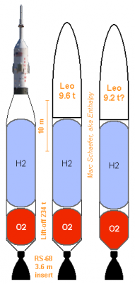
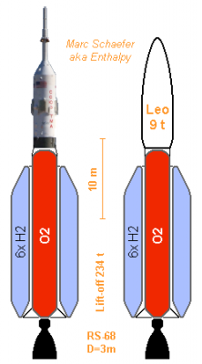
You expected it: light rocket structures make Single-Stage-To-Orbit (SSTO) possible, so here's an example. The single RS-68 is widened to D=3m (weighing 6.9t hence) but has a temporary restraint insert to maximize thrust at lift-off. An added deep throttle mode around 20% thrust would be very useful. Lift-off mass is 234t, leaving 23.1t at propulsion end, or 9500m/s performance for Low-Earth-Orbit (Leo). The central tank contains oxygen. D3.2m H20.5m made of AA 7022 profile, t1 = t2 = 1.5mm, a = 45°, with the extrusion direction tangential. Walls weigh 2.9t, heads 0.2t, foam 0.1t. Six lateral balloon tanks contain hydrogen. D2.0m H18.8m made of hot-rolled and welded Maraging steel, 170µm thin. The engine pushes their base. They hold only the internal pressure: 1,0b+0,5b+0,2b. Each skin weighs 193kg, its foam 71kg, six tanks total 1.6t. Thin aramide can cover the foam at the top, but something must prevent an impact during the fairing's separation. This leaves 11.4t for the payload, adapters, fastening rods for the side tanks, electronics, leaving around 9t payload. A Soyuz at 7.5t would even afford some heat shield and parachute to recover the engine if it were reusable. Tank mass is only 23kg per ton of propellants, and the payload is 3.8% of the lift-off mass, nearly as good as a multi-stage launcher. If this stage were to serve as a side booster, it would have two bigger hydrogen tanks instead of six small ones. Marc Schaefer, aka Enthalpy
-
At the oxygen tank of Delta IV's Common Booster Core I gave as one example, hydrostatic pressure produces a stronger stress in the walls than thrust does, so putting the profile's extrusion in the tank's tangential direction is better. The profile can consist of AA 6082 with t1 = t2 = 1.6mm and a = 45°. The booster's wall weighs then 8.1t instead of 5.9t, but if keeping the thinner axial extruded profile at the hydrogen tank only, the wall weighs 6.6t. To roll the extruded profile to the tank's radius, one known solution is a temporary filler in the profile. Other prospective ways: The outer skin could be warm and the inner cold when rolling. This could be done right at the extruder, by cooling one side first. Could the extruder's die produce a curved profile? Electrical discharge can machine a curved die. In both cases, the profile could be stored as a coil immediately when produced. An extruder bigger than usual might produce all wall material for a rocket stage in one step. Instead of storing a coil, the profile could be welded immediately into a wall by a continuous process. Some alloys are better welded hot. Later weld joint corrections are possible with the healthy alloys cited. Marc Schaefer, aka Enthalpy ================================================================== In some cases, profiles lighter than t1 = t2 = 1.6mm would be preferred. Extruded profiles exist with t = 0.25mm. They use to demand weak alloys like AA 6063 and small lateral dimensions. The extruder's force seems to limit it, not the alloys' capability, so a specially built machine may produce thinner skins of stronger alloy. Open profiles, having for instance T-shape stiffeners on a single skin, are easier to extrude, need less material and can be thinner. Such panels made by extrusion demand additional stiffeners in the other direction: a rocket tank can have tangential rings and axial extruded panels. While I trust them far less than closed profiles at rockets, such open profiles build already the fuselage and the wings of most aircraft; some of them might be extruded, to save money and maybe improve reliability. Marc Schaefer, aka Enthalpy
-
Nearly all launchers have isogrid tanks. They do so to avoid buckling and nothing else. Are you sure you're speaking about liquid rockets? Since liquid rockets with composite tanks are extremely uncommon. I should have made it clear at the beginning of the topic: it's about liquid propellant launchers, not solid missiles, which is a different world.
-
Buckling IS the only reason why rockets have isogrid panels, added rips and the like! Stiffness against axial bending, longitudinal compression, and others, would be best overcome with plain sheet. The corrugations, or zigzag, or call them as you want, are vertical. They follow the extrusion direction which is parallel to the rocket axis. Though, we could wrap the extrusions in circles or in a helix (possibly with several threads) in some cases where pressure in the tank creates more stress than acceleration does. No worry for the few G then, their direct effect on the sheets is really negligible. The most common shape (for 40 years) is an isogrid. From a thicker aluminium sheet, a milling machine leaves thick ribs on a (generally triangular) pattern, and thin sheet between them. The resulting panels are welded together. And, my mistake, T-profile ribs exist for decades: http://en.wikipedia.org/wiki/Isogrid http://femci.gsfc.na...grid_Design.pdf or Google isogrid, then select "pictures" which illustrate my obscure formulation of non-uniform thickness. That is: to obtain flexural stiffness from a given material volume, you better concentrate matter at narrower thicker places. And dome-shaped honeycomb as well has been around for a long time.
-
Oops. The extruded panel for the Common Booster Core would have a=60°, not 30°.
-
Hi Matty and all, thanks for your interest! That's perfectly true, many stiffeners have been invented, tried, and several types are used presently. They all make the panels hollow, to get thickness hence stiffness without the weight of a solid panels (that's because stiffness varies as the third power of thickness, so a non-uniform thickness is better). In the nice link you give, fig 1 type is used at airframes. A reliable bond between the skin and the sheet stringers is difficult to obtain, and I suppose this bond would require too much work for a launcher used one or few times. Though, inter-stages use often stiffeners of folded sheet, rather in an omega shape than a T. The sandwich panel at fig 3 has even higher performance because it puts most material at the extreme locations of the thickness. Because of accessibility, the skins are glued to the central honeycomb. Glueing is mistrusted in rocketry - much more so than welding - and it makes difficult to weld such panels to other parts, because glue burns at heat and pollutes the joint. The bond between the skins and the honeycomb is little stressed and glue is good enough for it, but for a tank, the panels (the skins) must also be bonded with other parts like tanks heads and inter-stages, strongly and tight, and I know no good solution for it. I haven't seen cylindrical honeycomb panels but they probably exist. Shapes neither cylindrical nor conical are much more difficult and I doubt they've been made, so the tank heads would use a different material. One further difficulty at cold tanks is the dilation difference. When the tank is full of liquid oxygen or hydrogen, or is being filled, near parts of the panels have very different temperatures, and I distrust glue under such conditions. Yet alone cold is bad for glues. For that purpose, a milled panel, or I say a welded one, is safer. It's done on combat aircrafts, where the wing's skins have "integral stiffeners" in one direction (a single part, 10m*20m, milled by a machine bigger than that, nice toy...), and on rockets, as on fig 2. As an improvement over fig 3, the rips are better on a triangular pattern, making an "isogrid". Easy now with CNC milling machines. This isogrid may improve a bit if we give the milled rips a T shape. This is possible with the cutters that produce woodruff keys (or better, an optimized shape with central cut): http://en.wikipedia....utters-Keys.jpg http://en.wikipedia..../Milling_cutter but milled shapes must still be open where the cutter plunges, limiting the rips' resistance against buckling. I have confidence in weld joints for having welded by myself aluminium alloys without worries. I suppose aeronautic and space designers distrust welds because they use unsound aluminium-copper alloys like the AA 2219, but the AA 6005A and AA 6082 are really safe, and the AA 7022 allegedly as well. Hence, I'm happy that the extruded profiles can be assembled by welding. Further, extrusion puts the welds in a little stressed direction and can make the material thicker there, nice. Marc Schaefer, aka Enthalpy
-
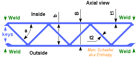
Hello everybody! Rockets must be light to attain a high speed, but their thin structures, pushed by the engines, are threatened by buckling. Usual tank construction includes sheets milled down to an isogrid structure, or omega stiffeners welded on a sheet. I propose to assemble rocket structures from tailor-made extruded profiles instead. http://en.wikipedia.org/wiki/Extrusion Extrusion can produce thick profiles consisting of thin walls that build closed channels. Such walls are well supported hence strong against buckling. The extrusion direction parallel to the rocket axis has advantages. All walls bring strength against rocket bending moments and axial compression. And since extrusion companies can deliver parts 30m or 50m long, a complete stage can consist of extrusions assembled only side-by-side, with little stress at the joints. Many materials can be extruded. These aluminium alloys are interesting: - AA 6005A. Yield>215MPa, Young 69.5GPa, 2710kg/m3. Easier to extrude, keeps its strength at weld joints. - AA 6082. Yield>250MPa, Young 70Pa, 2710kg/m3. Still easy to extrude, keeps a good strength at joints. - AA 7022. Yield>420MPa, Young 72Pa, 2760kg/m3. Harder to extrude, loses some strength at joints. http://aluminium.mat...ect/default.asp These alloys stay ductile at cold, even 20K. Their weld joints are ductile even with low-tech methods like TIG or MIG: easier, safer. AA 7020 would even regain its full strength after a week at room temperature. Extruded profiles exist with walls <0.25mm thin, width >700mm, hard alloy like AA 7075... To my understanding, each of these parameters just increases the necessary extrusion force, so I avoid to demand all extremes simultaneously. And since an extrusion machine costs a few 100k€, it can be made specially for the rocket production plant. More to come, including drawing(s). Marc Schaefer, aka Enthalpy ================================================================== Here the structural skin of a stage consists of extruded profiles welded side-by-side: The view is parallel to the rocket's axis and the extrusion direction. A propellant can be at the inner side at tank sections, or something else at inter-tank sections. Any insulating foam would probably be outside the skin. Depending on the extrusion machine, the width of a profile can be 200mm or more, so the profile can be curved or flat. A D=5m body would consist of 80 profiles for instance, welded side-by-side on one tank height, or better, on one stage height. If you feel this is much joint length: - These alloys like welding, as opposed to AA 2219 - The process is automated, and the quality of apparent joints is easily checked - Think and the joint number and length at omega stiffeners - Don't travel by ship The profile can be thicker at the joints, build a groove where the joint will be, and have keys to hold the parts precisely during welding. Very useful at least for manual TIG process. The keys also protect the joint's rear side against air when welding. Welding things like tank heads, interstage adapters, engine thrust rings... on the profiles weakens them a bit, but local reinforcements can compensate this. Reinforcements parallel to the extrusion direction and fitting between the profiles (machined narrower there) lose no strength at the profiles and take the full stress over, to cross the skin's weaker position. Marc Schaefer, aka Enthalpy ================================================================== Let's take a Zenit first stage as an example. The RD-171 engine pushes 7.9MN, the stage has D=3.9m, h=32.9m and carries 327t of kerosene-oxygen. AA 6082 can have t1 = t2 = 3mm, a = 45°, B = 40mm and b = 34mm. Then it withstands - without any safety factor - 31MN compression and 30MN*m bending moment. This skin weighs 11.1t. Better: AA 7022 with t1 = t2 = 2mm, a = 45°, B =44mm and b = 40mm. With no safety factor, it withstands 35MN compression, 34MN*m bending moment, and weighs 7.6t. Tanks heads may add 0.5t, foam 0.2t if any, the engine 9.8t. Even with the engine-to-skin transition and the interstage, this can be lighter than the original 27.6t stage dry mass. ----------- More difficult example: Delta IV's Common Booster Core. The RS-68 pushes 3.3MN. D=5.0m and h=34.9m (cylindrical section) to carry only 200t of bulky hydrogen-oxygen. AA 6005A shall make t1 = t2 = 1mm less difficult. a = 30°, B = 34mm and b = 32mm. With no safety factor, it withstands 13.5MN compression, 17MN*m bending moment, and weighs 5.9t. Add 0.7t for the tank heads and 0.3t foam, and the tanks weigh 35kg per ton of propellants. That's as little as the Shuttle's external tank, which didn't have to withstand the push of a first-stage engine. Marc Schaefer, aka Enthalpy