Tom Booth
Senior Members
-
Joined
-
Last visited
Everything posted by Tom Booth
-
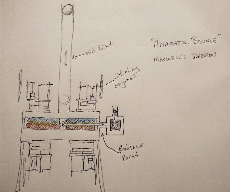
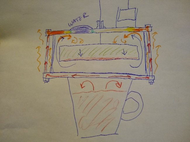
Incidentally the counterbalance could rotate to one of two positions. If it is turned upside down, this would reverse the heat separation so the more energetic hot air molecules would end up at the top of the chamber the cold at the bottom. In case it isn't clear to everyone, the red and blue object inside the large base is a regenerative heat exchanger. The red, naturally represents the hotter side, blue the colder. But as pointed out, if desired this could be reversed. The large heat exchanger is composed of material similar to very fine steel wool in thin layers that the air in the chamber passes through as this light weight heat exchanger is worked up and down due to the changes in pressure within the "bounce space" relative to atmospheric pressure. The black square is a counterbalance made of some heavier material, so that the small block on the right matches the weight of the regenerative heat exchanger perfectly. The little ball above the counter balanced is another small ferrofluid coated magnet in a very small cylinder. This creates a perfectly air tight frictionless seal the same as the larger heavy ferrofluid covered magnet.
-
I thought the annotations on the diagram should be sufficient for most people. And the diagram is pretty self explanatory I think. The link is just some additional more in depth explanation for anyone who might need it or want it, but if anything about the diagram isn't clear, I'm here to answer questions. No, of course not. If valid, violating a law of the universe is impossible, naturally. But some machines might appear to violate the second law, but of course there is always an explanation. This "thought experiment" is based on some well established and demonstrated principles, like "adiabatic bounce", heat of compression, cooling by expansion, balance beams and so forth. Oh I forgot to mention that instead of a steel ball, This device used a magnetic ball or cylinder coated with ferrofluid. Likewise with the counterbalance plunger and pivot bearing. Theoretically the components then are nearly frictionless in operation and so consume almost no energy.
-
I think that maybe this could actually work, almost. Feel free to ask questions about this here, but for expediency, an explanation of the theoretical operation of this Maxwell's Demon can be found here: https://stirlingengineforum.com/viewtopic.php?f=1&t=5338&p=18503#p18503
-
I didn't say it isn't interesting or potentially worth exploring, just that your question did not specify a heat source. If the heat source is finite it would be used up. Drained quickly as it went to work output, turning the flywheel and churning the air and making noise etc. I haven't given the other option much thought. If heated continually with a heating element... Let's consider... Heat goes in, gets converted to work output. If the Carnot flow through theory is correct, the interface between the two cold plates would receive considerable "waste heat". Is there active cooling there of any kind? If not, and the Carnot limit is correct, the interface I think, would be flooded with heat and the engines would all cease operation. Do you wish to explore the alternative Tom Booth hypothesis as well? Assuming you do, in that case the engines should continue running, so long as the heat is supplied, as the activity at the cold interface is basically null. You simply have pairs of engines sharing their heat sources and converting that heat to work output. The cold side being largely uninvolved in the operation except as far as providing a "floor" for the engines "adiabatic bounce" space as I've previously attempted to describe. Do you understand the concept of "adiabatic bounce"? I could post some explanatory videos, but as that seems to be frowned upon here, perhaps you can look it up and find them yourself if interested. Basically, though, if you have adiabatic expansion and contraction this will result in a continuous oscillation, which "ideally" or theoretically would continue indefinitely. Of course, with loses to friction etc. The oscillation will gradually wind down. A String engine, in actuality, or in essence, appears to be such an oscillator. On that note it might also be helpful to look up "Rüchardt experiment". And/or "Rüchardt method".
-
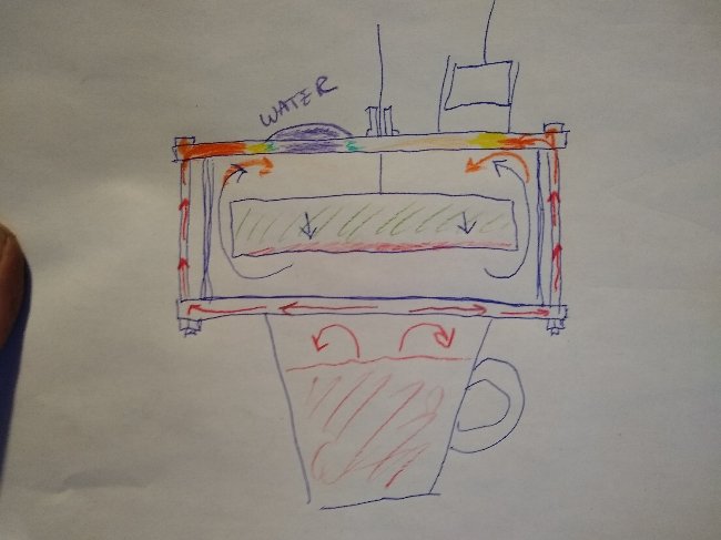
Heat travels in three dimensions, (at least). It does not confine itself to the two dimensional plane where we are debating the "gradient" or lack thereof. My diagrams illustrate what is happening with the heat dispersal on the vertical axis rather than confining the observation to the horizontal plane seen by the thermal camera. The working gas being heated by the heat input at the perimeters would be expected to disperse or distribute the heat evenly and uniformly from under the top cold plate. If the bolts are removed as a source of heat influencing the working fluid above the displacer this will not happen and the entire top plate can then remain cool. Heat dispersal is not a linear "flow" in one direction, nore is it confined to a plane. The dispersal is outward in all six spatial directions and every direction in between, which of course is why it is so difficult to do these experiments and one must have the utmost vigilance to control the heat flow as it attempts to disperse itself in ALL directions. It is not seeking out, or being drawn to the cold in any way shape or form. The dispersal is completely random in all directions. I was not evading anything, simply trying to point out what is going on in the vertical plane, which you guys were neglecting that you seem to still not be accounting for or have some unwillingness to take into consideration. This is your round-robin. You tell me the details of your proposed setup. Is your heat source finite, like a hot piece of metal or infinite like an electric heating element? May as well ask what would happen if you tied a leprechaun to a unicorn. The Carnot engine is admittedly just mythology. A recognized impossibility and unfalsifiable. As such it does not even rise to the level of meeting the guidelines of this "speculations" forum. An interesting point in that good electrical conductors are generally also good heat conductors. Good electrical insulators are often also good heat insulators. In my opinion in conducting experiments with beat it is helpful to view the heat in terms of how an electrical current would be viewed. If you want to control the "flow" of heat, you need to use effective conductors and insulators. Except that I think heat is even more prone to short circuiting. I would not be necessarily say heat and electricity are the same thing, but there does seem to be some close correlation. That's why I have speculated that heat is likely something more, or other than simply transfer of kinetic energy. Infrared light is considered a heat source. So maybe heat is something akin to an extension of the electromagnetic spectrum, or some such thing. However, I'm more interested in what it does and how to control it rather than what it is. It would be nice if we could pin that down though. Heat, what is it? Might be a good topic for another thread.
-
What would be the heat source? As I said, heat is your consumable "fuel". So anything like a finite source of heat like a hot metal disk would result in the heat being converted to work output, quickly diminishing. I had an odd thing happen recently while experimenting with the setup. Some heat was building up in the glass dome with the thin insulating lid over it. The engine had been running for quite a long long time. No recording was being made. Some steam was still getting in under the globe. The full heat of the steamer continued below the engine. After maybe an hour of undisturbed continuous operation with the lid on, whens the lid was finally removed the engine stopped immediately. This happened several times, but it was necessary to let the engine run for a very long time and for some heat to build up. Of course, theoretically, (former conventional heat engine theory that is) letting out the heat from under the glass globe should help cool the cold side, let out the "waste heat" relieve the bottle neck and allow the engine to run better. However the opposite happened, repeatedly. But as I said this would require leaving the engine running undisturbed for very long periods of time, without removing the insulating lid from the top of the glass globe. It seemed as though the heat building up under, (or within rather) the glass globe assisted the running of the engine. Removing that heat by venting that space with fresh air caused the engine to stop immediately. My tentative hypothesis to explain this is that, as observed previously by myself and others, approximately 1/2 the energy to run the engine comes frome atmospheric pressure driving the piston back inward after the expansion stroke. Under the glass globe, in this case would be the immediate "atmosphere" for the engine. The only thing not covered by insulation is the top of the piston. As the reaction was instantaneous, causing the engine to stop immediately I can only see one explanation. The air under the globe gradually heated up due to the work being applied and possibly some of the steam escaping from under the engine that got through the Aerogel and under the glass globe. That trapped air was also being agitated by the flywheel, much like Joules paddle experiments agitated water, heating it up. This heat, trapped under the dome was being recirculated to some degree, the excited air molecules above the engine impacting the top of the piston. This likely did not warm up the top cold plate of the engine under the insulation though as that was protected by the Aerogel blanket. Lifting the lid broke the homeostasis of this recirculating heat input above the engine, causing the engine to stall, but it would always start right back up easily and continue running with the lid off. This effect takes a very long time to manifest though. Maybe an hour or so of undisturbed operation with the glass globe covered. Seemed very strange at the time, but I think I understand now what was going on. Of course the probes should help confirm or refute this. It does not change my hypothesis that the top of the engine under the Aerogel stays cool.
-
What is "the engine"? Carnot limit says "IMPOSSIBLE" for ANY engine to get better than Carnot efficiency (calculated from the ∆T) "rejecting" no less than the reciprocal. So a little model Stirling on a 20% efficiency supposedly MUST "reject" the other 80% to the cold side or could not complete a single revolution or a single cycle. I've done some common sense modifications to reduce heat loss like replacing the heat conducting bolts, changing the throw of the piston in some cases, adjusting the timing/advance, maybe incorporate a small regenerator and so forth, and have had engines run for long durations with no measurable heat transferring to the cold sink side whatsoever. Supposedly that should NOT be possible. Some kits give a lot of leeway as far as how the engine is assembled, so sometimes you see these engine behave in strange ways. Experienced model builders know how to build an engine from scratch, turning the cylinders on a metal lathe so I'm basically talking about customized engines constructed by experienced machinists not some imported piece of junk that can barely run no matter what you do to it. To put it bluntly: your engine is garbage and your experiment is garbage. You are in no way an experienced and knowledgeable engine mechanic or machinist capable of building or putting together a machine that would display any of the unusual characteristics observed in any of my experiments. If you would like to see at least some hit of the possibilities you would have to get out a screwdriver and pair of pliers and maybe a hand drill and go to the hardware store and make some modifications on that silly little engine. I've tried to be encouraging but you have been rude, arrogant, pompous, disrespectful, insulting, and you name it. You and your little band of hecklers. So "the engine" no, not "the" engine, not just any engine you happen to pick up on Amazon. A properly built and/or if necessary, modified engine. You are not going to see the phenomenon I've been writing about and video recording if you refuse to make some minor modifications to your piece of crap engine. Or you could watch my videos, but you don't like videos. If you won't listen and are just intentionally avoiding everything I say should be or needs to be done just in an effort to try to prove me wrong with your so-called crap, straw man experiment I don't see much point in wasting much more time here debating your pile of horse shit so-called experiment.
-
What question. And how is what I illustrated "irrelevant" You folks seem to have no comprehension of heat distribution in a Stirling engine. Don't know what more I could do to make it any clearer. The heat from the bolts is heating the top plate as well as the air inside the engine below it. The cold expanded air is forced upward directly impacting those hot zones around the perimeter every cycle. That would not be "replicating" your experiment, which is crap. I've already done experiments of that sort, with nylon bolts.
-
You do realize that if the top plate is continuously heated so is the working fluid every time it is shunted up or down. I try to get it through my thick head that not everybody lives and breaths Stirling engines every day the way I have for the last 15 years or so, so these things are not readily apparent I'll try drawing a picture. Hopefully that will make things clear. If effectively you have six heating elements distributed around the cold plate, along with hot convective air currents, that is inevitably also heating the cold expanded working fluid above the displacer. The working fluid is constantly in motion so the heat gets washed out, distributed more evenly as time goes on.
-
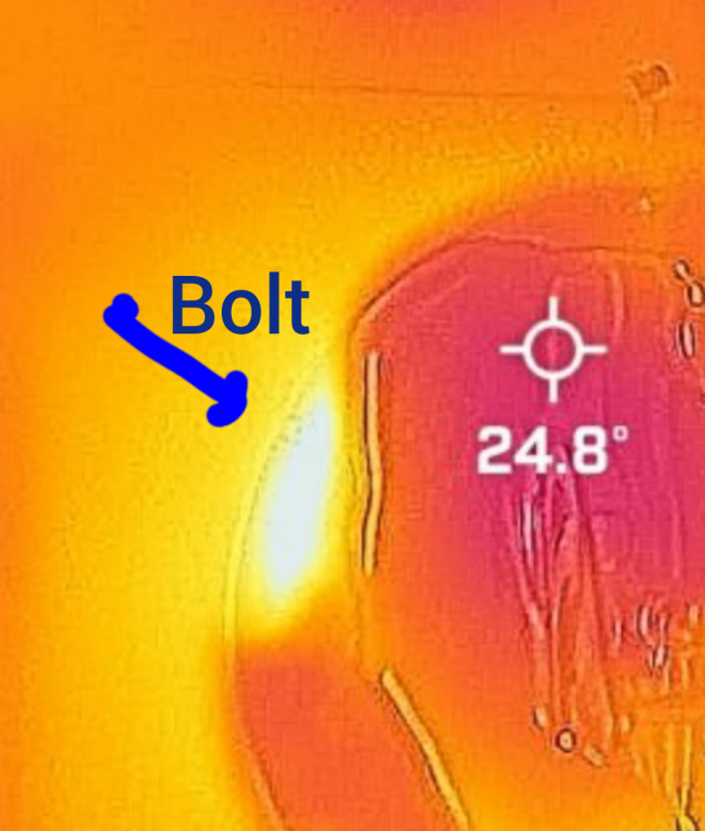
Sure Looks like a temperature gradient to me. White hot at the bolts transitioning through yellow, orange,violet, purple,to nearly black.

-
The relevant Heat transfer through a heat engine under investigation is that heat entering into or passing through the working fluid and only the working fluid, which means eliminating, as far as possible, all other avenues for heat transfer. You made no attempt whatsoever in that direction as evidenced by the luminous glow of the "hot spots" on your model There is no hesitancy on my part to conduct experiments. That's an obvious mischaracterization. Well I'm glad to see some kind of effort being put into this but you seem completely unable or unwilling to entertain any criticism of your methodology. If your intention is to prove this experimenter wrong, there should at least be some effort put into understanding the protocol of my experiments.
-
The first prerequisite for replicating any experiment I've conducted, as I've mentioned previously, is to eliminate any metal heat conducting parts that might transfer heat between the hot and cold plates (i.e. begin by replacing the metal bolts, if present, with non-heat conducting bolts) otherwise it is the near equivalent of trying to test an electrical resistor with six conductors bridging the gap. You've conducted a strawman experiment that completely ignores this first prerequisite, among the several other conditions I've already outlined.
-
Then your experiment is off topic. This topic here: Is Carnot efficiency valid? Regardless of what you were testing your experiment is terribly flawed in the ways pointed out as you have not replicated the conditions I have clearly specified for making the observations I reported on. Perhaps, if you want to investigate that, you should start a new thread on the subject but you would need to clean up your methodology which demonstrated an extreme incompetence.
-
If anyone is interested, what I would consider my best guess at how a Stirling engine actually operates is this: When I first started learning about how to build a Stirling engine, an experienced model Stirling engine builder told me that the way be determined the throw of the piston, that is; the distance it should travel between TDC and BDC was to heat up the engine to whatever heat source is going to be used with the displacer down (covering the hot side, preventing heat from being transfered to the working fluid) then manually lift the displacer. The working fluid will then take in heat and expand, then watch how far the piston travels in the cylinder The piston has not yet been attached to the crankshaft or flywheel. Make the throw or the piston a little longer . He didn't explain exactly why. At the time I could not conceive of any good reason for making the distance the piston traveled MORE than it wanted to travel. I'm not sure he knew why. Some things are learned as a result of trial and error. Perhaps all he knew was that it works; to make the piston go a little further out than it "wants" to go naturally. Now I believe I have figured out WHY that works. To begin with, the engine is at thermal equilibrium with itself and the environment; then heat is introduced; then the gas expands and does work driving the piston. The gas transfers the energy of the expansion work to the piston. As the piston moves out it accelerates gaining momentum. Now once the energy that was added is all transfered to the piston, the gas has cooled back down to the original temperature. The piston, however must travel a little further. It accomplishes this using the stored up energy that was just transfered to the piston. This "extra" distance the piston has to travel means that the working fluid will be mechanically expanded while simultaneously continuing to transfer additional energy to the piston. Why does the gas still transfer energy? Because the piston is still moving and the expanding gas is still pushing it. The working fluid inside the engine "knows" nothing regarding the atmospheric pressure on the other side of the piston, so it is still doing "work", still pushing the piston, still loosing heat. In effect, the gas is undergoing a refrigeration process, the gas is being expanded. Rather than acting as a heat engine; due to the extra distance the piston has to travel as a result of its own stored up momentum; the engine has become a Stirling heat pump or cooler. An expansion engine. The working fluid undergoes a rapid decline in temperature and drop in pressure. Now atmospheric pressure drives the piston back inward and the process repeats. There is no "heat transfer" through the engine. No need for a sink. The engine itself effects its own cooling, which allows the piston to return under atmospheric pressure.
-
If I were for example, to place one ice cube directly on the table, and another ice cube over a cup of hot water perched on a metal scaffold, the scaffold consisting of two metal plates connected together by metal posts, what would be the result? I would think the same result as seen in this experiment (by our esteemed Swansont). The ice perched above the cup of hot water, thermally connected to that "hot reservoir" by a metal scaffold would, of course be expected to melt before the ice cube merely sitting on a table with no heat source whatsoever below it. What does this experiment tell us about what influence the engine running may or may not have on the ice one way or the other? IMO nothing as too many variables are not held constant, not controlled or entirely unknown (in this case apparently intentionally withheld i.e.: conductivity of the countertop, as if the material and conductivity of the object a piece of ice is sitting upon has no influence)
-
Actually, your setup is somewhat novel. I suppose I could,... Well "replicate" may be the wrong word. I have two of these acrylic top engines. I could run one on a cup of hot water with ice on top, one on a cup of hot water also with ice on top but not running. As these acrylic engines have no bolts that eliminates all extraneous variables I believe. Do you agree? The circumstance of ice on your countertop is very far from having all variables identical aside from the one variable in question. Under the ice we will have the engines and the cups of hot water and the table. The two cups can be heated up together in the microwave perhaps, to avoid having one cup cool down slightly while the other is being poured. Have I forgotten anything? Do you agree to this setup? The only variable will be engine #1 running and engine #2 not running. Would this be a fair and reasonable comparison? Perhaps I should manually work the flywheel back and forth on the non-running engine so the displacer does not act too much as an insulator sitting idle on the bottom of the non-running engine, or should we give it that advantage?
-
Only some? It needs to account for all of it if your assertion is correct What is being investigated is the Carnot efficiency limit, not any wild speculating on my part. At the ∆T in your experiment. What would the expected % of waste heat going to the "cold reservoir" be? Did you say boiled water and ice? There is a somewhat wild variable thrown in there, an additional heat source (ambient all around, temperature undisclosed) but neglecting that and being very generous, you've got what 27% efficiency? So my hypothesis is that the Carnot formula might not be totally accurate and may be underestimating actual efficiency. Does that not mean then that at an absolute minimum, 73% of your heat from the hot water needs to be passing through to the top of the engine? (The percentage Increasing as the cup of hot water cools down and efficiency drops) So your "It (heat conducted through the bolts etc.) needs to account for ALL OF IT" is not actually true. Anything less than 73% heat transport to the sink would invalidate the Carnot efficiency formula. Is that not correct?
-
I agree ice may not be ideal, why the next experiment will be using temperature probes. But it is possible, I think, to get by with ice if all the variables associated with it are kept constant. Kept in the same freezer, removed at the same time, distilled water without contaminants, same measured quantities of water used to make uniform ice cubes, etc. With a hot object between two engines, with nowhere to go except out as either work OR heat, through the engines working fluid and virtually nowhere else? Think. It won't necessarily overturn anything. It could absolutely confirm the amount of heat output predicted by the C. Efficiency equation. As I've said many times, I'm not trying to prove or debunk anything one way or the other. Just trying to get to the objective truth. I want to know how Stirling engines actually operate so some improvements can be made, if possible. On the other hand if their is zero waste heat or even a refrigerating effect at the sink, (outside surface of the two engines) that should be quite easy to determine as well. If one of those ceramic heaters is used between the engines and no heat ever appears on the ambient sides after hours of continuous running what would we conclude from that?
-
That would be difficult (exactly) since you were unresponsive regarding some of the parameters. Anyway I already have, many times, except for modifications: replacing highly conductive metal bolts, insulating air passages between the plates and so forth to eliminate extraneous variables. Some of your conclusions seem questionable. A metal heat exchanger doesn't conduct heat under water sitting directly on top of it, only to the extremities. Heat at the edge of a .metal plate remains only at the edge. No difference in conductivity between the metal of a heat exchanger and a countertop of some other, possibly non-heat conducting material, to name a few off the top of my head. Oh, did you suggest heat conducted by metal bolts to a metal plate remains completely localized Transfer of heat between air and metal vs air and another material is no different. If everyone is satisfied your results are conclusive I guess we can wrap it up. The lunatic, tin foil hat, perpetual motion crank has been proven wrong. Case cosed.
-
Just a few observations, not intended to be confrontational. Very glad to see someone else doing some experiments, thank you! 1)Curious about the ambient temperature. 2)Material the countertop is made of. (Conductivity compared with engine.) 3) it appears the six or so metal bolts are intact which hold the engine together and could act as heat conductors. 4) Convection of hot air transferring heat between lower and upper plates outside of the engine. Not trying to be argumentative but the bolts and convective air currents both outside the engine's working fluid could potentially account for at least some of the difference. Also the countertop, if of a less heat conductive material than the engines heat exchanger might absorb ambient heat more slowly, therefore transferring heat to the water at a slower rate. Of course if aluminum or copper or something could conduct heat to the water more quickly. Thank you! There seems to be some especially hot "hot spots" around at least some of the bolts. Unless maybe that is the cup handle? But at least two other such lesser apparent hot spots seem to coincide with the bolt arrangement.
-
There is also an old video of my attempts to start the same engine without insulation, and nothing rubbing on the flywheel. It had a few false starts also. The magnet has to be able to lift the displacer, which is a bit more of a job than just having the displacer attached directly to the crank. This was 9 months ago: the only "temperature reading" taken was with my fingers. The top of the acrylic engine body remained cool to the touch in my subjective estimation. So it stayed at least below body temperature if it felt cool to the touch. Well, how about just sticking with the math for now then. Do you have any problems with my calculations or statements in the two previous posts? Here: And here: https://www.scienceforums.net/topic/128644-is-carnot-efficiency-valid/?do=findComment&comment=1228952
-
OK. And? Was it's flywheel also dragging on some loose Aerogel insulation? Does your engine have a magnetic displacer? I agree the experiment was less than perfect in many ways, but once the problems were resolved, such as the insulation rubbing on the flywheel, the engine ran for another 3 hours. My phone ran out of video memory storage and cut out after about 2 hours but my understanding is without "continual cooling" the engine should not be able to complete a single revolution. I did, as I said earlier, trim away the insulation fibers that were rubbing on the flywheel and made some other changes. This time the engine started up and continued running more easily. That was also video recorded if you care to look at it.
-
At the start of our setup, we have ambient air, and everything else, the steamer machine, water, engine etc. all at (approximately) thermal equilibrium at 68°F (20°C, 293.25°K) Carnot efficiency, of course is zero. Now we plug in our "infinite" heat source the water simmers at 212°F but cools down a bit on its way up to contact the engine. (I'm at a fairly high elevation here though, so the boiling point is likely a bit lower than 212°F) I've selected a fairly reasonable temperature, (I think) as the high temperature in our calculations a bit below boiling (212°F) at an even 200°F (93.3°C, 366.5°K) Mostly I'm just taking a reasonable (realistic) set of temperatures that works out to an even 20% Carnot efficiency. In reality 200°F for the heat input is probably a bit high. I'm still working on ways of attaching temperature probes for more accurate readings. I did ask for opinions regarding where exactly the readings should be taken but got no response. There are 4 probes on one thermometer and 1 additional probe on my multimeter, then there is the thermal camera that can reveal spot temperature. I did install all new batteries in these devices and this seems to have largely resolved most of the slight discrepancies in the readings to within a few degrees
-
Still looking. In the mean time, would it be possible to get a response, or could someone actually commit to an opinion regarding how the percentage arrived at by means of the Carnot efficiency formula is to be properly applied in a real world scenario? Or alternatively, how it is to be interpreted as an upper ceiling (or whatever name anyone might want to call it) on efficiency for any given situation? Maybe there are more, but I've encountered at least two ways of viewing this percentage in my studies on the subject: Given a ∆T with the temperatures as follows 68°F (cold), 200°F (hot) works out to 20.01% This seems like a realistic example. We have some water at a constant simmer under the engine with an ambient temperature of 68°F Both hot and cold source are effectively infinite. We keep the steamer going continuously and the ambient atmosphere is effectively infinite. Mathematically this 20% arrived at works out as 20% of the absolute temperature scale. This is not just true of the two temperatures I have selected by some remarkable coincidence. It is true of any two arbitrary numbers plugged into the equation. I'm not of course saying that the percentage is always 20% The percentage is always representative of the low temperature subtracted from the high temperature and the "efficiency" is the ∆T. The temperature difference on the absolute scale. Always. At absolute zero, of course efficiency is 100% because the temperature difference is 100% of the temperature scale from the highest to the lowest temperature. If we take the temperatures 4°K and 0°K for example, our "hot air" engine will be 100% efficient though no air and no gas, not even helium can exist as a gas at 4°K We could take a high temperature of 5 trillion degrees C where nothing can exist but a quark-gluon plasma or some such and 0°K as our sink and the efficiency of our engine is again 100% Can we actually test the accuracy of this formula at these extreme scales? Probably not. So returning to a more realistic scale that at least can be tested experimentally, in theory, what does the 20% actually represent in practical terms? We know, factually, it is simply the temperature difference calculated as a percentage. Of course, I've dropped the decimal,just so we have a nice round number. Allegedly, so some of the literature on the subject, textbooks etc.relate, this temperature difference comprising in itself 20% of the absolute temperature tells us something more than just the temperature difference on the absolute temperature scale, but what exactly? As I see it we have two options, but which is correct, or can they both be reconciled in some logical way? I'll get into more detail when I have time. I have sent away for an "upside down" Stirling engine to run some tests as suggested by Ghideon's "rhetorical question" This is just something to do in the mean time. Get our facts and definitions straight. What is it exactly we are supposed to be testing? What does the 20.01% actually represent in real terms as far as actual heat input and heat and work output? And I would suggest we confine the discussion to Stirling type hot air/gas engines where only heat and work cross the system boundary, just to keep things simple. I.e. no fluids like steam, gasoline, diesel fuel, gas or air etc.
-
Just going back and looking through your past posts for your experiment proposal, and came across this. I don't think I answered that question directly, or maybe I did, but I'm not sure I understood the question at the time. I've been reading about and talking about conversion of heat into work for so many years now it's inconceivable to me that anyone with a knowledge of general thermodynamics does not understand this basic concept. That the heat input is converted to work is a given, is it not? It's just a question of how much is converted, but obviously "the energy that appears as mechanical work" is derived from the energy that originally entered the working fluid as HEAT. That anyone here with any kind of scientific background could even ask such a question is almost inconceivable to me. It is a well established fact that a heat engine converts heat into mechanical work. The heat does not turn the engine as it flows through to the sink to produce work like a water wheel. The heat is, or becomes the work output and the heat, as such vanishes. It is a bit difficult to wrap your head around, but when heat is converted to work in a heat engine the heat vanishes. The heat has gone out as work. What is left behind is COLD, which is what we perceive or measure as an absence of heat. When the heat goes out of the working fluid as work, the working fluid looses heat dropping in temperature, becoming cold. If the heat also continued on to the sink, that would be a violation of conservation of energy.