
Ghideon
Senior Members
-
Joined
Everything posted by Ghideon
-
 You mean that matter entering black holes is ejected through stars at some other point? If so, no that is not somerhing observations and current theories would say is physically possible.
 -
First comment, your paper says That does not sound correct. It can only be approximately valid for small masses moving in the gravitational field of a large mass. Example; a small masses will accelerate towards earth at 1g. But replace the small mass with a large mass, such as Jupiter. I do not think the result will be that Jupiter accelerates towards earth at 1g.
-
You might want to try the quote function in the sandbox
-
Thanks for the clarification! I suspected that expansion of universe was intended, that's why I stubbornly kept asking. The words have similar meaning over here as well, care must be taken so the correct physical concept is referenced. I'll read your proposed idea again using expansion wherever inflation is stated.
-
I'll try a logical explanation with more detail without referring to math of specific laws of physics this time: Let's say two hypothetical devices are working perpetually* as a unit without external energy source. Perpetual motion device A feeds energy (1) into device B and then device B feeds energy (2) to device A. Since no external energy is added and operation is perpetual there is no internal energy wasted; efficiency is 100%. Device A runs from the energy provided by B and B runs from the energy provided by A. Hence, over time, A must supply B with the same amount of energy that A would require to operate in isolation. And B must provide A with the same amount of energy B would require to run in isolation. So the result is that the only way the device A and B could work as a 100% efficiency perpetual motion device together is if they could do so in isolation. A and B are perpetual devices on their own or the device (A+B) is not a perpetual device. In other words you can not build a perpetual motion device unless you have a set of perpetual motion devices. This does of course not alter the fact that perpetual motion machines is not possible. It is just a way of showing how OPs setup is not working in a general case. (I answered from phone earlier and was unable to use an image. This is pretty much same as @Janus but I had started drawing already so posting probably does not harm.) *) Not possible! Only used to setup the explanation.
-
No. It makes no difference; perpetual motion is not possible even if combining devices. The overall physical laws still applies.
-
I may have misinterpreted the following: Cosmic inflation does not seem to be as widely accepted as the expansion of the universe. Not all physicists* think there is enough evidence to support the phenomenon. The inflation phenomenon does not push away massive bodies. The inflation ended before massive bodies formed, inflation is an early period of accelerated expansion. Therefore I asked for a reference supporting your statements. Here is paper on cosmic inflation that might be a good introduction. https://arxiv.org/pdf/astro-ph/9901124.pdf. *) See for instance criticisms section on wikipedia: https://en.wikipedia.org/wiki/Inflation_(cosmology)#Criticisms
-
According to current theories inflation ended at some early time. You write as it is an ongoing phenomena: 1: Do you have a reference where atomic physicists state that inflation is pushing objects away? 2: Do you maybe mean the current expansion of the universe instead of the theory of early cosmic inflation?
-
I usually copy/paste or drag and drop images into the edit box. Works fine from computer. Ok. Do you mean cosmic inflation? Cosmological inflation, or just inflation, is as far as I know a theory of exponential expansion of space in the early universe.
-
Hello. Can you post something more than just a link?
-
Not sure that I agree. Is c really the base for all languages, including functional programming languages (for instance ML) ? I believe it is quite possible to understand the concepts of for instance Java or C# without first learning c.
-
I would want to participate in discussing of your findings, initially to see if your ideas and arguments are supported by mainstream science. This is a discussion forum, so your discovery will be discussed. The outcome of such a discussion will partly depend on what and how you choose to contribute. (Side note: My first language is not english, but on this forum language is seldom a problem. General attitude of most members is helpful; language issues are identified and overcome)
-
I briefly did before moderators removed parts that are not needed to start a discussion. I dont think Phi’s question was answered. can you post (a less detailed) answer how evolution is fundamentaly different for humans?
-
Even if the idea does not work I think the presentation deserves some credit; it allowed for a proper analysis to identify issues and opened for a fruitful discussion. And also credit to @Janus for the clarifying!
-
Thanks for the reply. I think I might need to clarify; the exhaust leaves the the engine in the y (vertical) direction. Unless the exhaust is slowed down in y direction, relative to the engine, the fuel will not be recovered. Since the exhaust has mass the change of velocity in y-direction (=acceleration) will require energy. If you check the setup for conservation of momentum for instance I think you could spot the issues that emerge?
-
Hello! I have not yet analysed all details but initially this looks like a variant of reactionless drive. It is not possible to recycle the fuel. Slowing down the exhaust to recycle fuel will halt the rocket.
-
(1): [math]t'= \gamma (t- \frac{vx}{c^{2} } )[/math]
-
Good point! It was some decades ago but I still remember how cool it was to build stuff. I think the ball-n-stick model could be fun to combine with a (free) online tool such as Molview. I'll use Sensei's picture as an example. If kid asks "what have I built? What does it do?". Personally I couldn't identify the compound in the picture but a few minutes in Moleview tells us that it (likely) is "Proline, an alpha-amino acid" and "Amino acids help break down food, support growth, and repair body tissue." http://molview.org/?cid=614 There are of course other methods. Personally I don't know much chemistry so this is a quick method to be able to tell some basic facts.

-
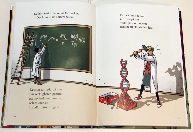
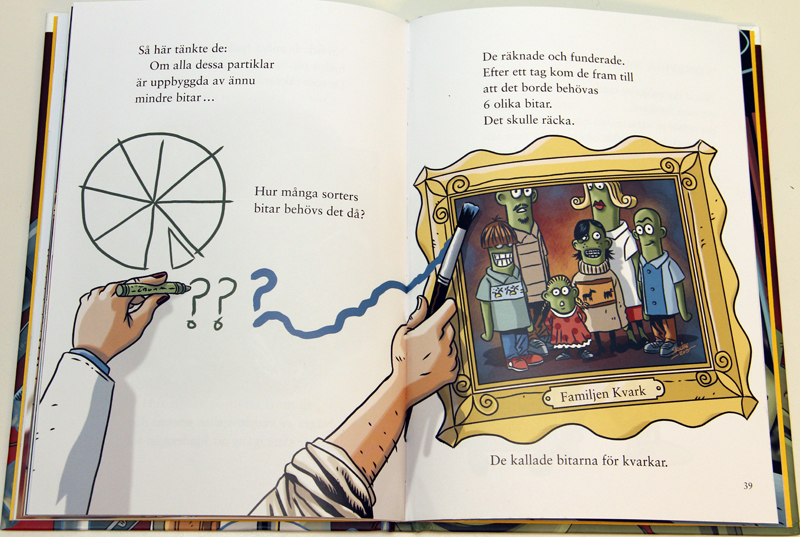
Cool! For atoms and particles (and science in general) I have used books with lots of pictures so that we can both read together and/or kids can explore the book and ask questions later. Here is an example, the author explains that there are two types of scientists within the physics, the physicists who calculate mathematically how things work and the physicists who break things down so that the counting physicists can figure out why. The book* is excellent but I've not been able to find a translated version. I post it as an example even if it is not in english. Introduction to standard model; how many types of Quarks are required? Your kid is probably already past this stage already but others might find it useful. I've used Toca Lab which focuses on playing around with the elements and the periodic system. pros: All 118 elements can be "discovered" in a periodic table focused layout. Some basic behaviour included; gases "hover", solids drops down on the table. Opens for discussion based on periodic system and elements. AFAIK no commercials Cons: Focus is on playing, not scientifically correct details. Example: new elements can be "created" from other elements. Kids won't learn detailed scientific information without interaction with an adult or older kids. Here is a review: https://www.commonsense.org/education/app/toca-lab-elements Here is a PDF with all elements already "discovered": https://s6.pappasappar.se/wp-content/uploads/TocaLab_PeriodicTable.pdf. The app starts with an empty one. *) https://www.bonniercarlsen.se/bocker/163790/om-pyttesma-partiklar/
-
Hello @Owen Martin Ok! Your suggestions does not seem intuitive to me, even without using math i get: -If the goats were identical and not possible to tell apart, would that change the possibility to win a car? No -If instead of goats there are nothing behind the two doors so that an example is Car/Empty/Empty, would that change the possibility to win a car? No The 4 possible outcomes does not have the same probability. It seems you think it is a 50/50 chase of picking the car in the first selection. That does not seem intuitive since there is one car and two goats. I prefer to use math to show that 50/50 is incorrect. But I think it is can be fun exercise to see that by intuition a 50/50 answer seems incorrect. Try this thought experiment: First change the rules as a comparison. Let Monty do the first move and open a door showing one of the goats. Monty must pick a goat, he is not going to reveal the car. Your chance is now 50/50 to get the car from behind one of the two remaining doors. Compare to the original rule is that you must choose first. Monty must now show a goat, he is not going to reveal the car. Now is it intuitive that the outcome is not 50/50 in this case? Intuition may not give the correct answer, but it tells that 50/50 seems wrong since the rules are changed from the case above where the outcome was indeed 50/50. It does not seem intuitive that you have the same chance as in the case where Monty had to remove one of the goats first. Logic and "intuition" can help in the analyse but to get the correct answer I prefer math.
-
Just trying [math] for the first time... (Vfy)^2=(VisinΘ)^2+2ay⋅Δy [math] V_{fy}^{2} = V*sin( \phi )^{2}*2a_{y}* \Delta _{y}[/math]
-
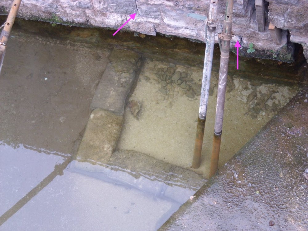
Agree, I can't see anything new. Not sure if it means anything but are there other cracks than the large one?
-
If I put my pedantic head on for a while then your comment dimreepr actually seems like scientifically sound reasoning and not a joke One reason why I asked about freezing in my first post. In the area where I grew up it was not uncommon for subsurface ice to push stones upwards: ref https://www.skogskunskap.se/vagar-i-skogen/drift-och-underhall/slitage-nedbrytning-och-skador-pa-vagen/skadekatalogen---vad-kan-vi-gora-at-vagskadorna/
-
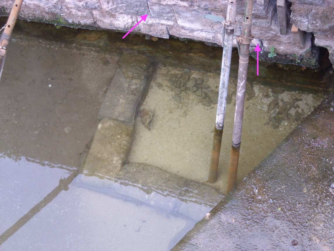
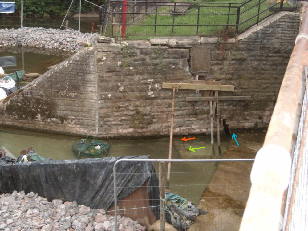
Some thoughts: The bottom of the crack is very close to what looks like a solid construction not covered by water. Is the part of the wall (that has not failed) resting on top of this structure? See blue arrow in picture. The red arrow shows some sort of structure under water. Does that continue in under the failing part of the wall? If so, is the gap at the green arrow a crack? Does it look like the thing underwater at the red and green arrow has moved down?
-
Thanks for the update! +1