Peter Dow
-
Posts
129 -
Joined
-
Last visited
Content Type
Profiles
Forums
Events
Everything posted by Peter Dow
-
 Not at all. I advocate only a tiny tweak to the Earth's ecosystem. Actually I do understand that the "downside" is only for blood-sucking disease-spreading mosquitoes and the like and there is no "downside" for us humans nor for any of the other animals who are now unfortunate enough to get their blood sucked and get disease as a consequence too. Oh do you post here in order to "win many followers"?
 -
Species go extinct all the time and the ecosystem manages fine. We shouldn't bother ourselves too much if in future some animals can no longer eat blood-sucking disease-spreading mosquitoes which we have extincted. I expect that such animals would not be too bothered themselves but would just as easily find something else to eat. Either way I am not going to research that question myself but be my guest, research away. Just don't expect your results to get in the way of medical and health progress world-wide, because that would be unrealistic.
-
Humans wiped out mosquitoes (in one small lab test) If we could eliminate a species, should we? Science News. BY SUSAN MILIUS, 8:26AM, DECEMBER 17, 2018 "For the first time, humans have built a set of pushy, destructive genes that infiltrated small populations of mosquitoes and drove them to extinction. But before dancing sleeveless in the streets, let’s be clear. This extermination occurred in a lab in mosquito populations with less of the crazy genetic diversity that an extinction scheme would face in the wild. The new gene drive, constructed to speed the spread of a damaging genetic tweak to virtually all offspring, is a long way from practical use. Yet this test and other news from 2018 feed one of humankind’s most persistent dreams: wiping mosquitoes off the face of the Earth." My opinion is YES we certainly should eliminate the species which is the main malaria-spreading mosquito, Anopheles gambiae and we should extinct that species without delay.It will be disappointing if this new method can't extinct the species as we hope but no-one should dare to fault those who rush to find out if it will work.I trust that the World Health Organisation and national equivalents such as the U.S. Centers for Disease Control will soon be planning to apply this supremely efficient pest control method against every blood-sucking parasite which is a disease vector with the intention to extinct them all!Genetic engineering and medical science has served humanity with as momentous a breakthrough as was as the discovery and use of vaccines and antibiotics.Congratulations and all the rewards on Earth and all the blessings in Heaven to those who have contributed. Let's roll.
-
‘Jeremy Hunt, the health secretary, deserves credit in arguing for extra money. But Mrs May will find the cash because public dissatisfaction with the NHS is at its highest level for a decade.’ Photograph: POOL/Reuters Without doubt, the UK editorial of the year. Thank you Guardian editorial writer, whoever you are. Might you be interested in editing BBC news and current affairs? If so, you have my vote for what it is worth! Hallelujah! A UK newspaper of record finally GOT IT!
-
Engineering of the FIU pedestrian bridge, which collapsed
Peter Dow replied to Peter Dow's topic in Engineering
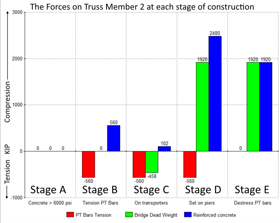
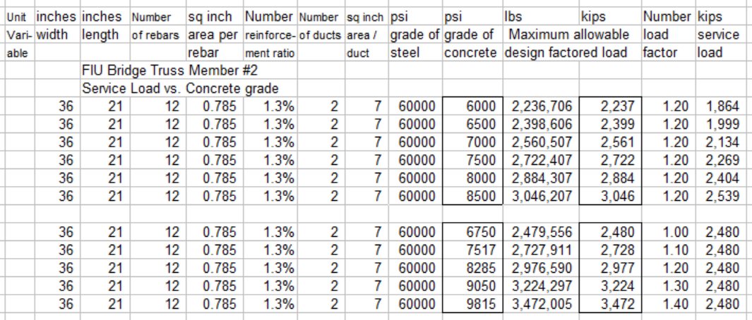
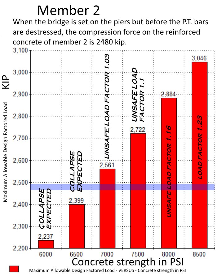
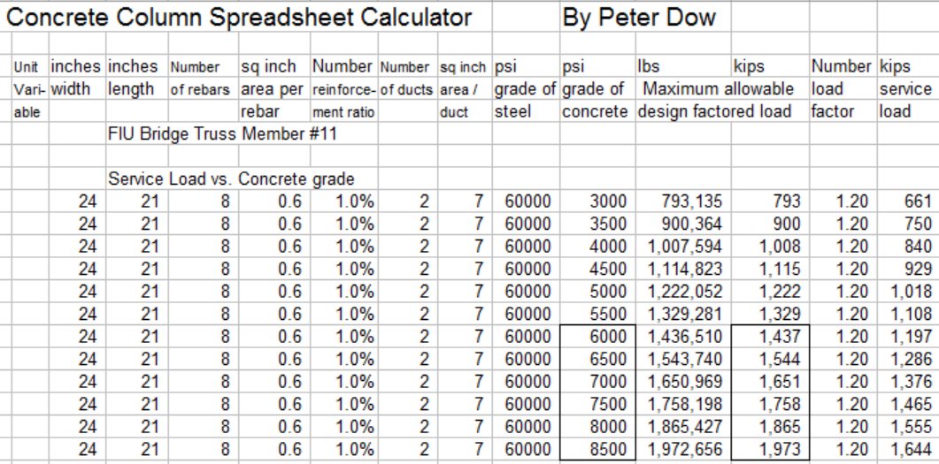
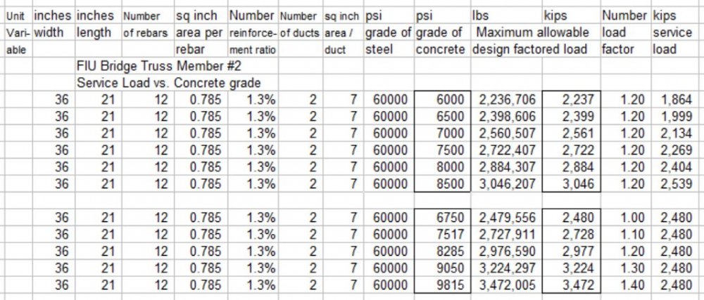
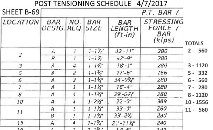
Now considering member 2, which survived intact, member 2's "SECTION C-C" - - has 12 x size 8 (diameter 1", area 0.785 sq-in) reinforcing bars and member 2's P.T. bar force setting is 560 kip (same as member 11). My truss calculation results were - in transit tension of 458 kip in situ compression of 1920 kip Now let us consider what all those forces together in the sequence they were applied mean for the compression force on the reinforced concrete of member 2. At the critical "Stage D", when the bridge is placed on the piers but before the P.T. bars can be destressed, the reinforced concrete of member 2 has to take the full compression force of 560 KIP from the P.T. bars under tension plus the 1920 KIP dead weight of the bridge to suffer a total of 2480 KIP of compression force, but member 2 was able to cope with that load of 2480 kip, so I calculated the maximum allowable design factored load to find out how strong the concrete must have been, in this table from my concrete column calculator and this bar chart. Therefore the survival of member 2 may be expected, during Stage D anyway, if the strength of the concrete was 7,000 psi or more, albeit a reasonably safe load factor (at least 1.2) is not to be enjoyed until the concrete hardens to at least 8,285 psi. Simply applying commonly used engineering design equations for concrete columns suggests clearly why member 2 survived but member 11 failed. Pate's under-design of member 11 was significantly further out of code than was his design of member 2. Attached image files ...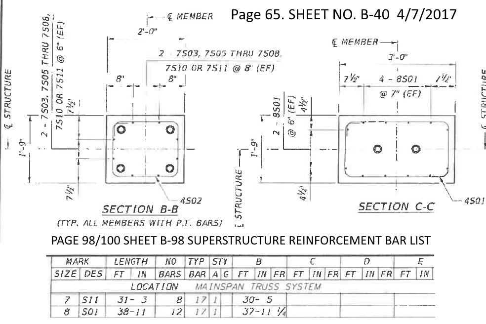


-
Engineering of the FIU pedestrian bridge, which collapsed
Peter Dow replied to Peter Dow's topic in Engineering
Rubbish. M11 could not service a 1927 kip service load therefore it was under-reinforced and too small. M11 was under-designed in many ways. -
Engineering of the FIU pedestrian bridge, which collapsed
Peter Dow replied to Peter Dow's topic in Engineering
The "right page"? If you are doing your own calculation, then is it not for you to decide what is the "right page"? I have given page numbers on many of images which are snapshots from that 110 page pdf. There is a page index on page 2, however the sheet numbers don't correspond to the pdf document numbers, the pages are not in the correct order and there is no way to search for text, so finding your way around that document is a pain, sorry. I didn't even use that pdf, which was only released recently, to build a model for my truss calculations, but the 2015 MCM Design build proposal pdf, which contains the proposal documentation, which is here if you are interested. http://facilities.fiu.edu/projects/BT_904/MCM_FIGG_Proposal_for_FIU_Pedestrian_Bridge_9-30-2015.pdf That document is at least searchable by text, which is something, though it lacks any information on the P.T. bars for member 11 which were an after thought. (continues later) Hmm but the concrete column design equation variable fy is the yield strength, not "ultimate" and example 13 says "Grade 60 (fy = 60 ksi)." The engineering plans (on page 3 of the pdf, sheet B-2), specify "All reinforcing steel shall be ASTM A615 Grade 60", so I think I am right to use 60,000 psi for my calculations, but I stand to be corrected if you know better? Your equation which I acknowledged calculates an average stress, which is not the same as the "actual" stress, which is too complicated to be so easily calculated. It is an appropriate consideration in my failure investigation. Oh, all my adult life, I have investigated the UK which is one big failure in oh so many different ways. Well speak for yourself. I, "inevitably", have determined that Pate's design is dangerously, recklessly and culpably out of code as regards the critical component member 11 which failed - and that's all a jury needs to know to convict of involuntary manslaughter. I haven't withdrawn my figures, no. Understood. The post tensioning force however - in this case 560 kip - contributes to the service load, as does the force from the rest of the truss - the dead weight of bridge - 1367 kip (as does the pedestrian live load but I am ignoring that for now). The service load requires to be factored and the factored load must be less that the Maximum Allowable Design Factored Load. What makes it technically "under-reinforced" is the calculation of Maximum Allowable Design Factored Load, which is pitifully too little to cope with a service load of anything like 1,927 kip. If it had been a higher percent, the relevant technical difference it would make would be to the calculation of Maximum Allowable Design Factored Load, not to the percentage per se. You misunderstand if you have, or you think I should have, a bee in my bonnet about reinforcement percentages. I am interested in performance.
-
Engineering of the FIU pedestrian bridge, which collapsed
Peter Dow replied to Peter Dow's topic in Engineering
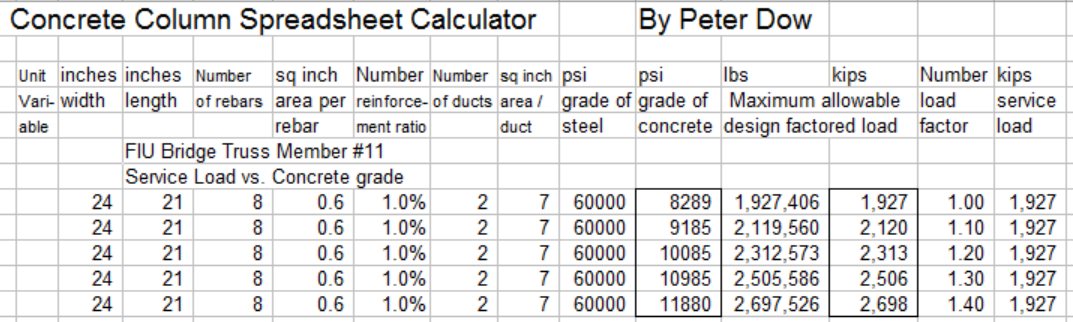
I see you have posted (or edited) 12 minutes ago. Before I reply to your more recent post, I have more to add to my last post. The calculation I had done was for a Maximum Allowed Design Factored Load of 1,927 kip. When I calculate, as I should, for a service load of 1,927 kip, the required concrete design compressive strength required reach ridiculously high values - for example,10,000 psi for a load factor of 1.2 - see attached image. This demonstrates that a 21" x 24" concrete column member with 1% areal rebar and 2 x 3" diameter ducts is a non-starter to bear a service load of 1,927 kip.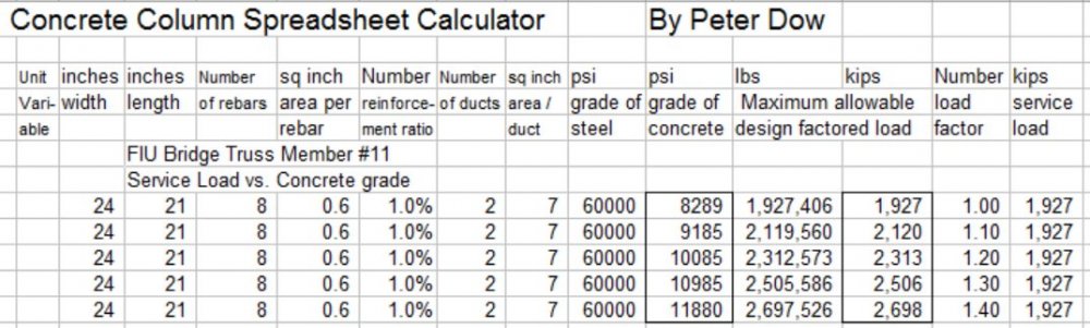
-
Engineering of the FIU pedestrian bridge, which collapsed
Peter Dow replied to Peter Dow's topic in Engineering
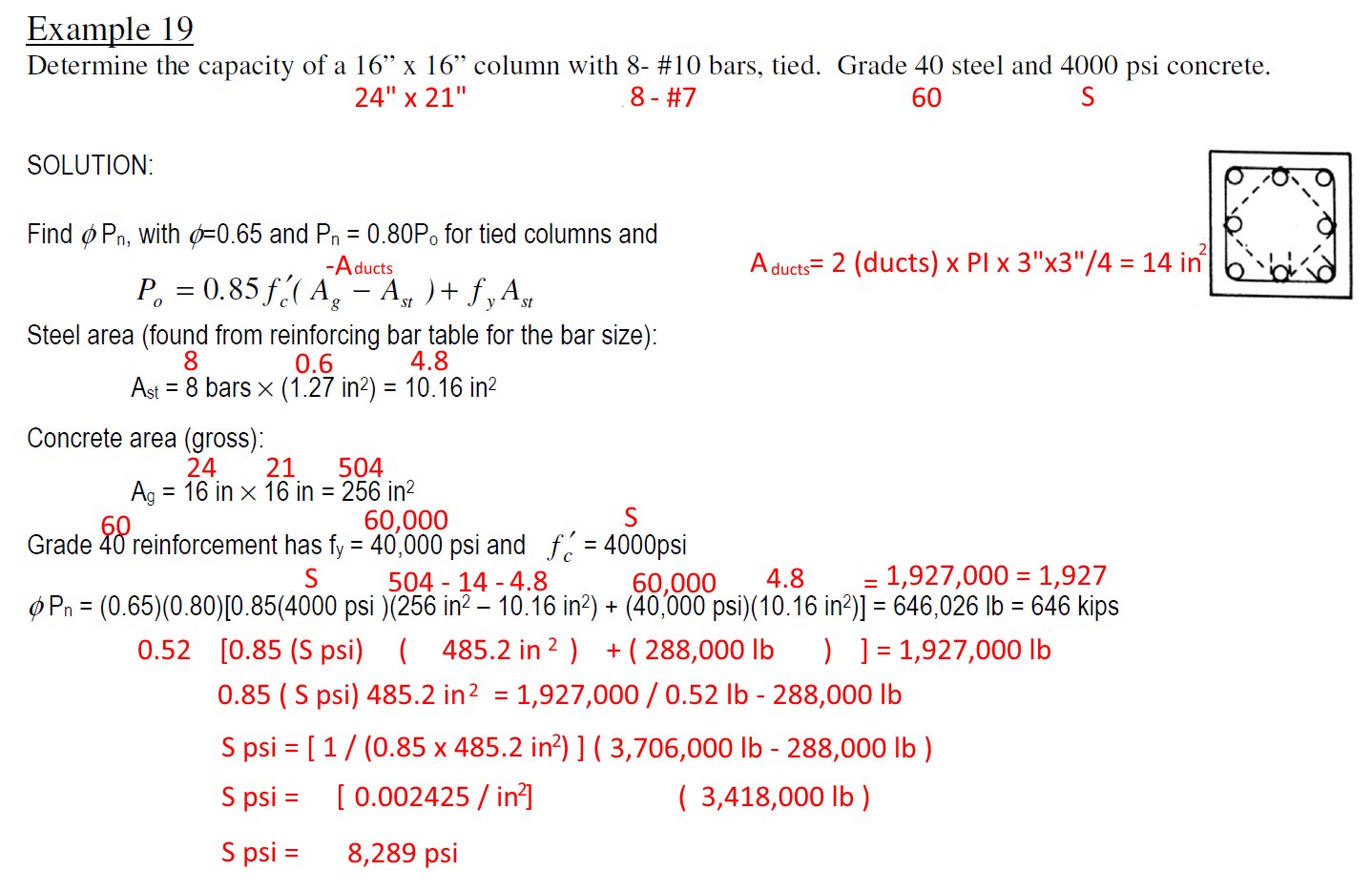
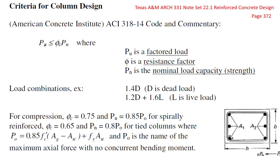
Whose profession? Sakharov's? Those who are worthy of nomination for the Sakharov prize for freedom of thought? Or the profession of those who persecuted Sakharov, those who are not worthy? Agreed and that's easy to work out. That takes a lot of working out and there are many modelling assumptions and simplifications on the way but that's the figure I worked out for the total compression load on member 11 at stage D, when the bridge was on the piers but before P.T bar destressing had taken place, sure. I acknowledge your calculation but it was not a calculation that I found useful. It is not appropriate to use your calculation to deduce that concrete of a compressive strength of only "4,000 psi" would be allowable or acceptable for an engineer to design such a size of member to sustain such a load. There are, as you allude to, many "factors" to include in the recommended engineering design methods, equations and codes. For my concrete column calculations, I adapted the method described in this pdf file http://faculty.arch.tamu.edu/media/cms_page_media/4198/NS22-1cncrtdesign_3.pdf See "Criteria for Column Design", page 14 / 43 of the pdf, labelled "Page 372" of the Texas A&M book / document which the pdf is an extract from. See also "Example 19", page 36 / 43 of the pdf labelled "Page 394". The equations there specify factors multiplying together to increase the minimum acceptable concrete strength for a "concrete only" design by a combined factor of about 2.26 = (1 / (0.65 x 0.8 x 0.85),. So more like 2.26 x1,927,000/485.2 = 8985 psi would be required to design a concrete-only column of those dimensions to carry that load. I have just today included the factor for the rebar compressive strength and rearranged the design equation to solve for f'c "concrete design compressive strength" and calculated 8,289 psi - see the attached image files.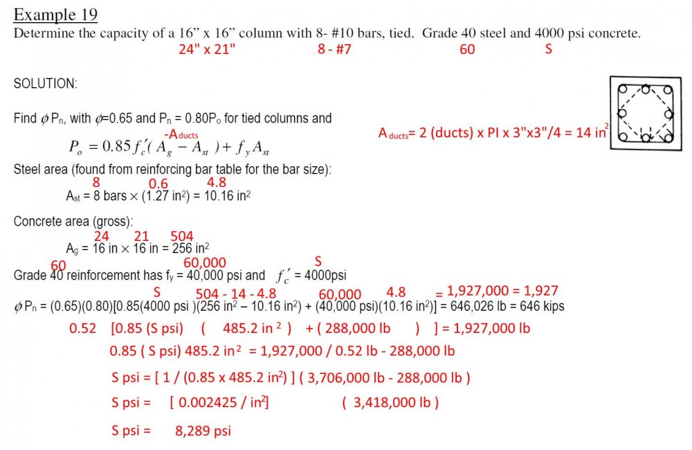
-
Engineering of the FIU pedestrian bridge, which collapsed
Peter Dow replied to Peter Dow's topic in Engineering
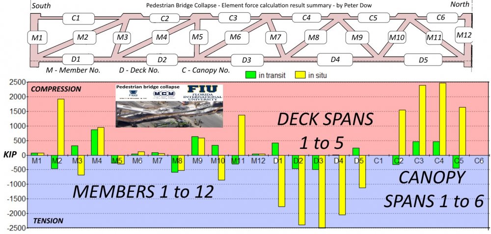
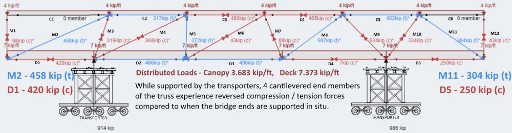
Well I didn't work out the forces by how "it looks" but by using an online truss calculator to calculate the forces. The force on a truss member depends on its location in relation to where the support nodes are and on the overall weight the truss is carrying. During transit on the transporter, the support is not at the ends, but on the penultimate end nodes, so member 11 serves as a tie, experiencing tension of 304 kip. When sited on the piers then support nodes are at the very ends, so member 11 serves as a strut, experiencing compression of 1367 kip. which explains the 1367 kip compression on member 11 when the main-span is placed upon the piers Which calculates the 304 kip tension on member 11 when the main-span is being carried by the transporter, which in turn explains why the P.T.bar tension force has to be greater than 304 kip, but not why it needs to be as much as 2 x "280 kip" or "560 kip" or 184% the size of the tension force it must resist, when something smaller would do. I think I shall attach my images in case there is a future problem with my Flickr account.


-
Engineering of the FIU pedestrian bridge, which collapsed
Peter Dow replied to Peter Dow's topic in Engineering
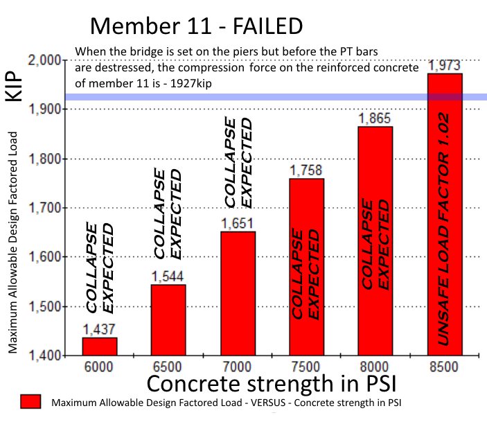
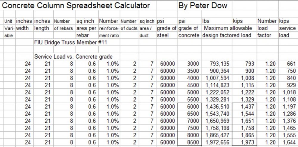
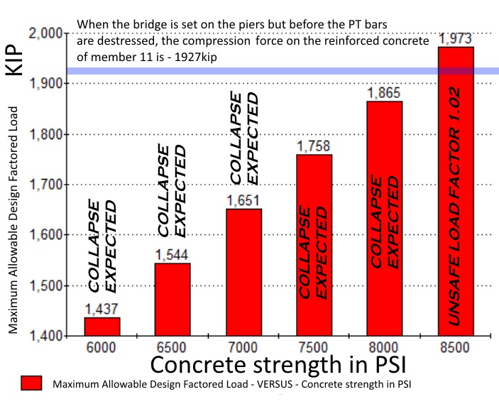
For the compression load it was being subjected to at "Stage D", when placed on the piers but before the P.T. bar could be destressed, "under-reinforced" certainly. I calculated the Maximum Allowable Design Factored Load for member 11, a 24" x 21" concrete column with 1% steel reinforcement (and 2 ducts) for various compression strengths from 6000 psi to 8500 psi and found these values. When the bridge is set on the piers but before the PT bars are destressed, the compression force on the reinforced concrete of member 11 is 1927 kip. 560 kip (from the P.T. bar) + 1367 kip (from the dead weight of the bridge) = 1927 kip 1927 kip is too much force for this member 11 to withstand, party because it has so little reinforcement. With more steel reinforcement, member 11 could easily have withstood 1,927 KIP. But it didn't have enough reinforcement so the concrete of the member suffered damage. Well let's stick to member 11 rather than discuss all concrete members, shall we? Damage was done at stage D - cracking, crumbling, crushing, fracturing, shearing - use any term you like or get on your high horse about any term you don't like, I don't mind - inelastic deformation or permanent damage - in the normal way damage is done to a concrete column that is suffering more compression load than it can survive by merely elastic deformation. However I don't claim that the member "failed" at that stage D, before destressing had begun. It appears that the member did not fail until the P.T. bars were being destressed, when strength which the P.T. bar was contributing to, was lost - strength which had been necessary to prevent the member from failing. I speculate that this was strength from static friction cohesion. Imagine you have three books - you stack them together and put one hand under the stack and another on top. So long as you press the books sufficiently firmly together, static friction will allow you to hold the books together and you can turn the orientation of the stack so that the books are orientated vertically. However, if you destress your hold, then static friction will lessen and the books will fall. -
Engineering of the FIU pedestrian bridge, which collapsed
Peter Dow replied to Peter Dow's topic in Engineering
Well I am not shy. -
Engineering of the FIU pedestrian bridge, which collapsed
Peter Dow replied to Peter Dow's topic in Engineering
Concrete is known to be strong under compression and weak under tension. Although concrete is indeed strong under compression it is not infinitely strong and it will fracture under a sufficiently strong stress. https://en.wikipedia.org/wiki/Compressive_strength https://en.wikipedia.org/wiki/Properties_of_concrete https://en.wikipedia.org/wiki/Concrete_fracture_analysis -
Engineering of the FIU pedestrian bridge, which collapsed
Peter Dow replied to Peter Dow's topic in Engineering
No problem. Yes. I am to Aberdeen what Andrei Sakharov was to the Soviet Union - a scientist, excluded by the academic establishment of Aberdeen and persecuted by the UK police state and courts for my pro-human rights political activism. "Bristol" huh? Aberdeen is known as the "oil capital" of Europe with ambitions to become the "energy capital" of Europe. Has Aberdeen sent our engineers to build a Severn Estuary tidal energy scheme yet? We can if the UK would like to pay for one such? -
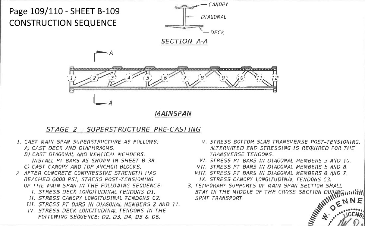
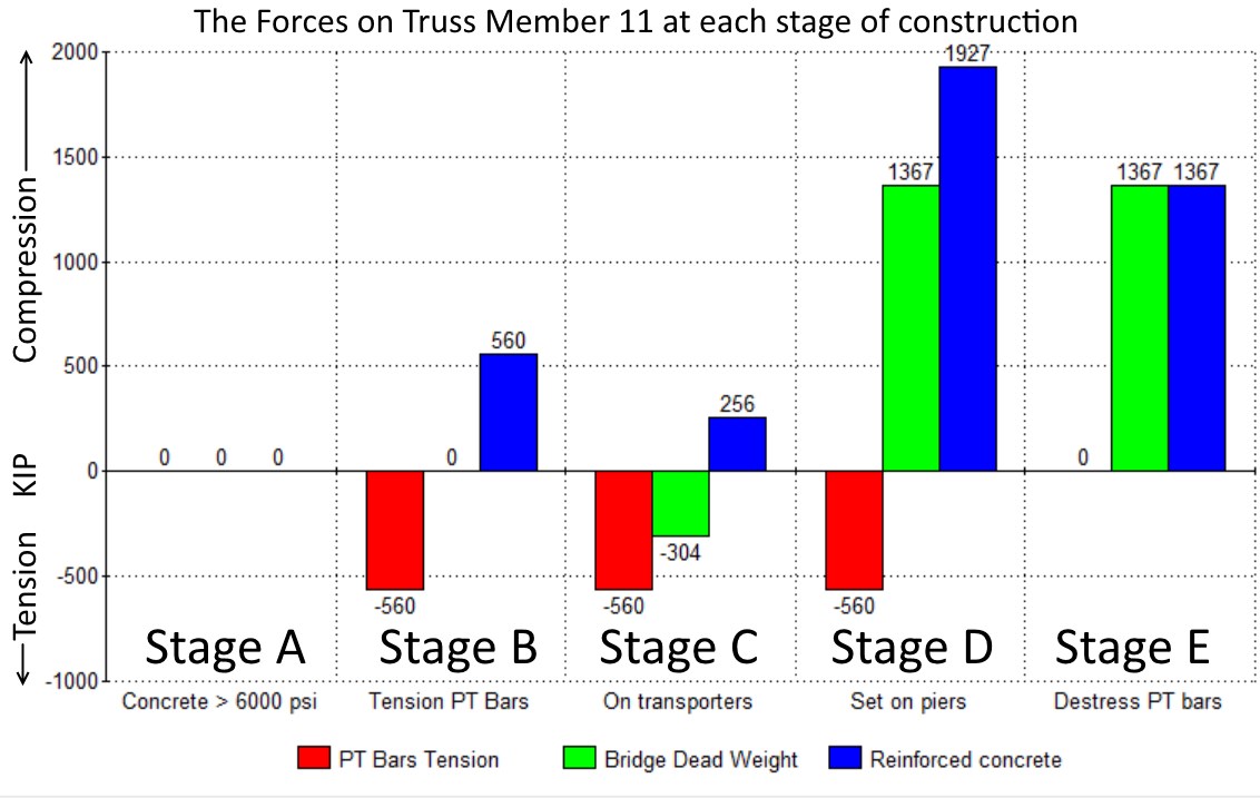
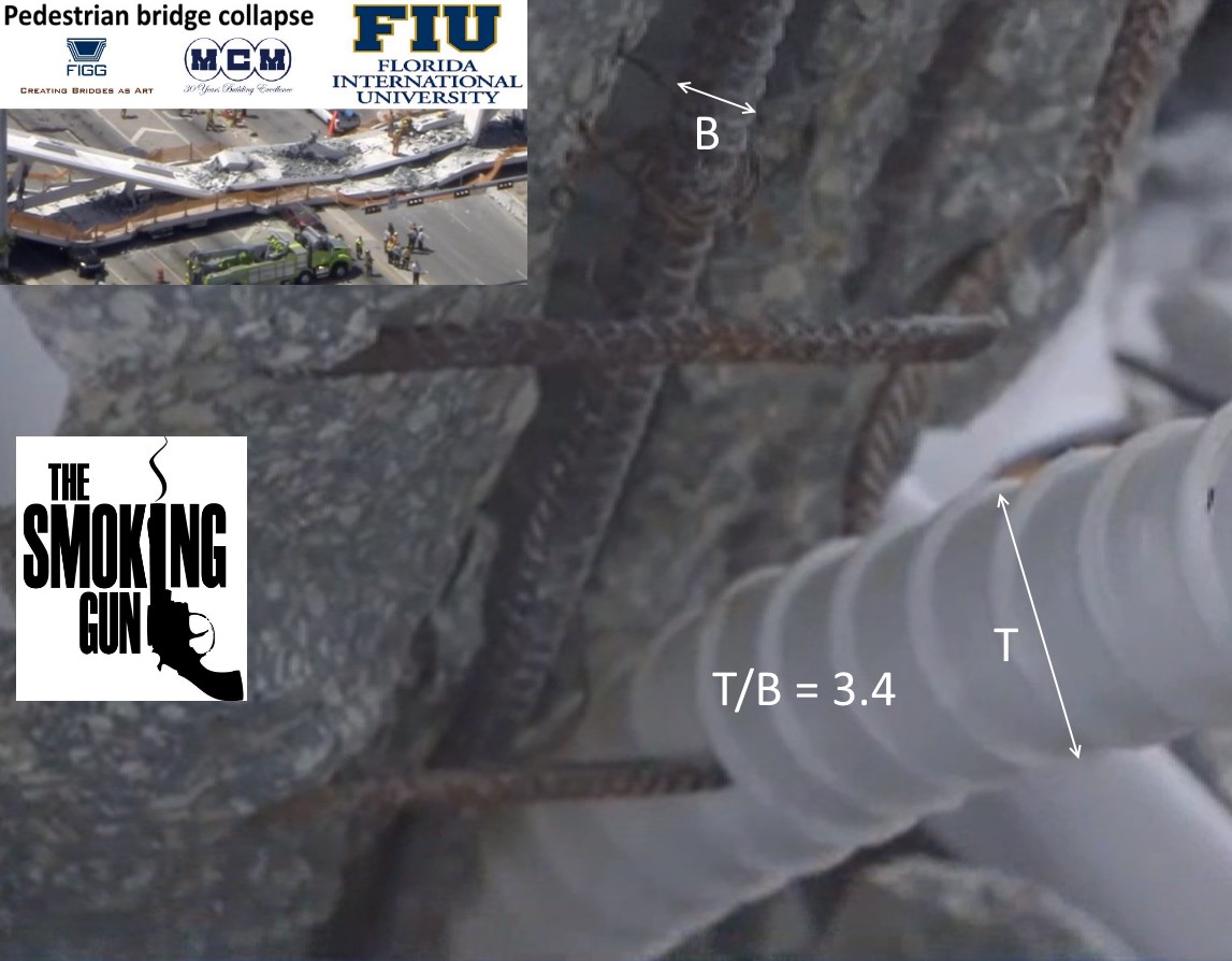
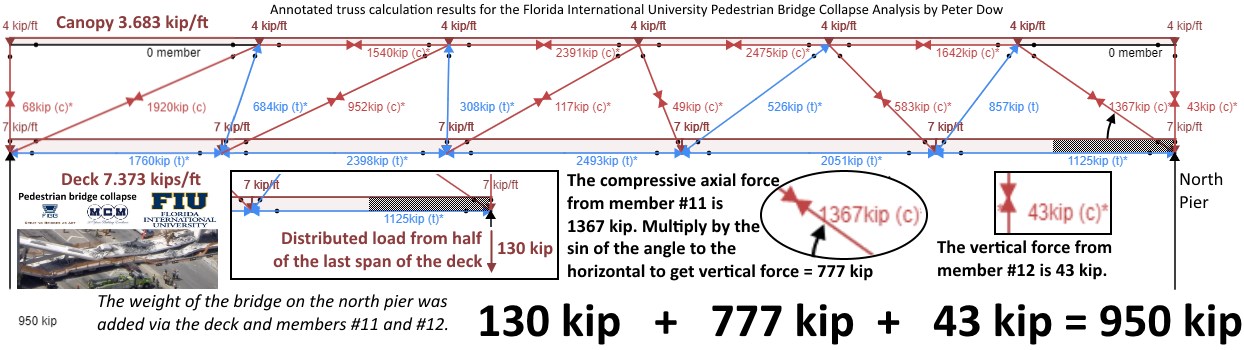
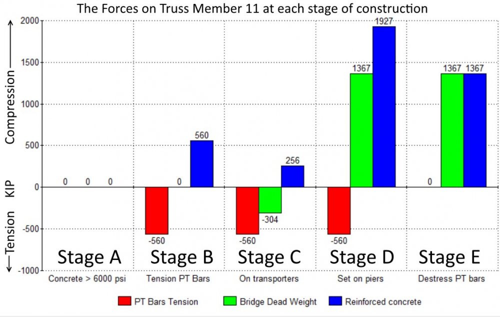
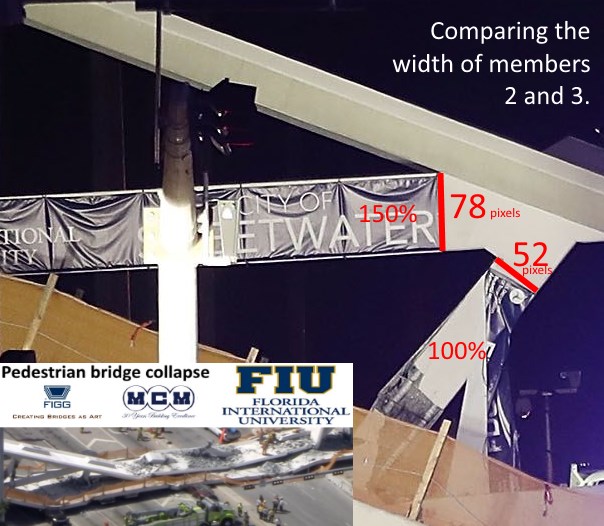
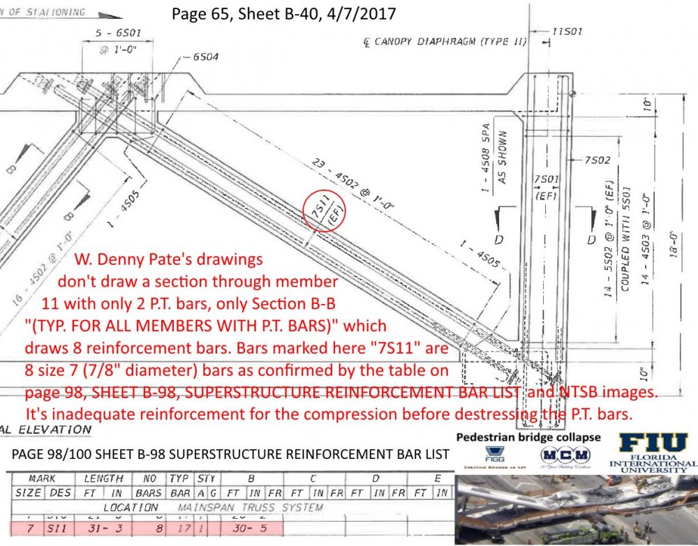
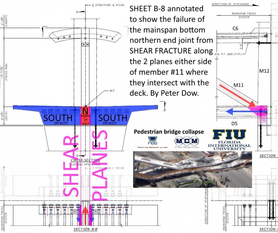
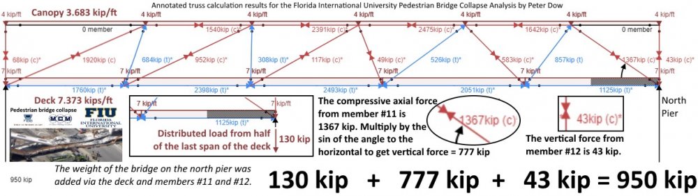
Wikipedia - Florida International University pedestrian bridge collapse The Florida Department of Transport has released the engineering design and construction plans for the FIU pedestrian bridge, which can be downloaded from this link. Florida Department of TRANSPORTATION - Denney Pate signed and sealed FIU bridge construction plans - 2016 & 2017 https://cdn2.fdot.gov/fiu/13-Denney-Pate-signed-and-sealed-FIU-bridge-construction-plans.pdf My analysis of these engineer's plans have revealed that my earlier suspicion that member 11 was dangerously under-reinforced has been confirmed, to such a degree that the collapse of member 11 (and consequently the whole bridge) under the compression load after the bridge was placed on the piers but before destressing was to be expected. The engineering plans, signed off by the "Engineer of Record", W. Denney Pate of FIGG, were at dangerously at fault and so the construction team by simply following the plans faithfully would have guaranteed the collapse of the bridge. The first point of concern to note from the engineering plans is that the plan's P.T. bar tensioning begins once the concrete reaches a strength of only 6,000 psi or more, as this quote shows - 6,000 psi is less than the final full strength of the concrete was expected to be (at least 8,500 psi) when it has fully set and in this case proceeding with the construction while the concrete was not fully hard was a contributing factor to the collapse. The next point of concern to note is that the engineer's plans recommend a P.T. bar setting for the 2 P.T. bars in member 11 which together total a P.T. bar tension of 560 KIP. The results of my truss calculations show that the dead weight of the bridge exerts on member 11 * a tension force of 304 KIP while the bridge is being transported and * a compression force of 1367 KIP when the bridge is placed on the piers, which is a point of concern to note. The P.T. bar tension of 560 KIP on member 11 is somewhat higher than it needs to be - I have suggested that a P.T. bar tension of 390 KIP would have been plenty. Now let us consider what all those forces together in the sequence they were applied mean for the compression force on the reinforced concrete of member 11. I have considered 5 different stages, A, B, C, D and E. The bridge collapsed as a result of damage to the concrete member 11 sustained in stage D, so the bridge never got to stage E in good order, sadly, but inevitably given the plans followed. Stage A The concrete has hardened to at least 6,000 PSI and so post-tensioning is about to begin but at this stage the mainspan is still resting on the ground, so there are no troublesome forces on member 11, no P.T. bar tension, no bridge dead weight and so the reinforced concrete is not being compressed very much at all except under its own weight and that of the canopy immediately above it, but we will ignore that for now. Stage B The P.T. bars of member 11 have been tensioned to the recommended amount - a total of 560 KIP and that tension force on the P.T. bars is being provided by an equal and opposite compressive force of 560 KIP on the reinforced concrete. But the mainspan is still on the ground so not much in the way of dead weight of the bridge to worry about yet. Stage C The mainspan has been lifted onto the transporters and now the dead weight of the bridge is exerting an external tension force of 304 KIP on member 11. This has the effect of reducing the compressive force on the reinforced concrete of member 11 by 304 KIP down to 256 KIP. Stage D In this case, "D" for danger and for "Doom". This is when things take a turn for the worse. The bridge gets placed on the piers and now the dead weight of the bridge is applying a compression force of 1367 KIP on to member 11. So now the reinforced concrete has to take the full compression force of 560 KIP from the P.T. bars under tension plus the 1367 KIP dead weight of the bridge to suffer a whopping 1927 KIP of compression force, which is more than member 11 is able to cope with, especially so if the concrete has not reached is full strength of at least 8500 PSI, as is shown in this table from my concrete column calculator and this bar chart. Therefore the collapse of member 11 must be expected if the strength of the concrete was only 8,000 psi or less and the plans only require that the strength of the concrete at this stage be at least "6,000 psi". A point of concern to note is that the plans only call for 8 number 7 (diameter 7/8" inch, area 0.6 square inches each, axially orientated reinforcing bars), just barely 1% of a reinforcement ratio for that size of concrete member. The compression strength of member 11 was 99% concrete by areal cross-section. Another point of concern to note is that plans only call for member 11 to be of size 24 inches by 21 inches in cross section. Whereas the equivalent member at the south side of the bridge, member 2 was 150% wider, 36 inches by 21 inches and although it was carrying a higher dead weight from the bridge, member 2 survived intact. Member 11 was not thick enough, it wasn't reinforced with steel bar enough, it was not strong enough to survive the forces it was subjected to during stage D. The P.T. bars, 1.75" diameter steel bars, didn't contribute to the long term compression strength of member 11, but actually contributed to ruining the long term compression strength in stage D. As I have noted there, W Denney Pate's drawings don't draw a section through member 11 with only 2 P.T. bars, only section B-B "(TYP. FOR ALL MEMBERS WITH P.T. BARS)" which draws 8 reinforcement bars. Bars marked here "7S11" are 8 size 7 (7/8" diameter) bars confirmed by the table on page 98, SHEET B-98, SUPERSTRUCTURE REINFORCEMENT BAR LIST AND NTSB images. The plans specify an inadequate reinforcement and inadequate compression strength of the reinforced concrete of member 11 to withstanding the compression load of 1927 KIP before destressing the P.T. bars, which would have cracked, crumbled and weakened the member 11 during Stage D. This was catastrophic damage which would sooner or later cause the member 11 to fail. Possibly at Stage D the cracked and crumbled concrete of member 11 was temporarily still being precariously held together by static friction increased by the additional compression on the concrete provided by the tense P.T. bars. (Sort of like if you crush a biscuit between your hands, the crumbs don't fall out until you release your grip.) This would explain why the bridge did not collapse immediately when placed on the piers but only when destressing of member 11 began and the already cracked concrete lost some of its static friction cohesion by the reduction in compression and only then did the member 11 shatter, collapsing the bridge. Member 11 was carrying the full weight of the structure. There is no redundancy in the FIU bridge design whereby other concrete columns can take the load if truss member 11 fails. It was all on member 11. When member 11 goes, the whole bridge goes down. This picture shows "the smoking gun" - far too small and far too few reinforcement bars, marked "<-B->". The picture also shows the broken stirrup reinforcement bars, which too, were inadequate to the task expected of them. Stage E. After destressing is complete. We don't know for sure if this stage was actually completely entirely but even if it had been, by that time the damage which had been done in Stage D was revealing itself and the member 11 was failing and bridge had begun the process of collapsing. There was no way to complete stage E successfully because member 11 was on a hair trigger to collapse because of the severe damage to the concrete sustained in stage D. The inadequate strength of member 11, alone, could be entirely responsible for the collapse of the bridge. Additionally, I have concerns about the failure of the bottom joint under shear fracture where member 11 connects to the deck and member 12. To my mind the responsibility for the collapse of the bridge lies with he who wrote those plans - W. Denney Pate. Nevertheless, I believe that others too had a responsibility not to allow citizens to pass or drive under any bridge under construction, before it has been completed and certified as safe. A collapsed bridge is a pity. A collapsed bridge falling onto citizens is a crime. Peter Dow's 'Truss Forces - The weak points of the bridge and the forces they failed under' picture album on Flickr Peter Dow's 'Mug Shots - FIU Bridge Collapse - Key personnel responsible' album on Flickr
-
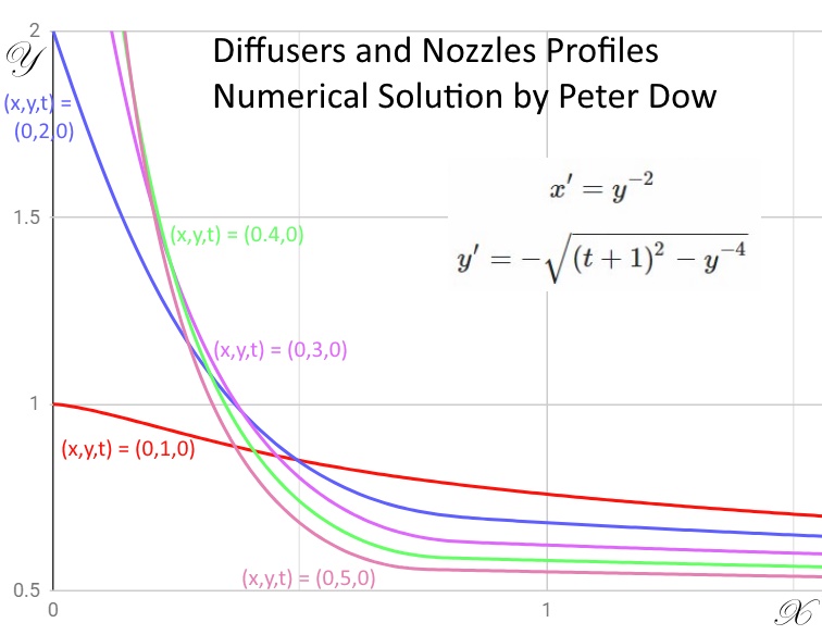
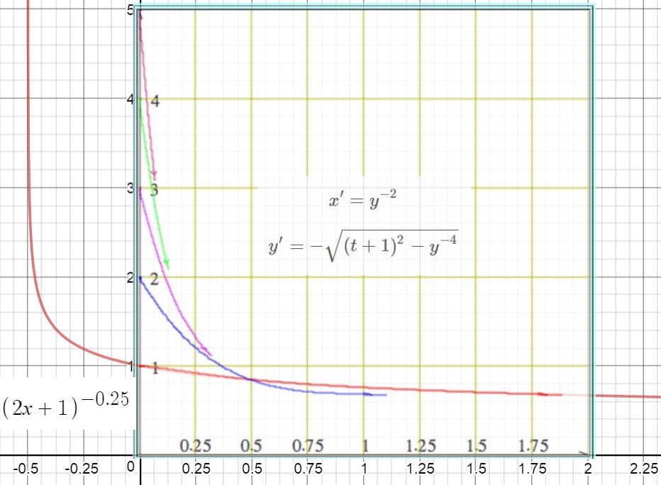
I derived this system of differential equations this week as I was researching possible profiles for water diffusers & nozzles, used when joining pipes with different bores. Mathematics: Solve this system of differential equations. \[ x' = y^{-2} \] \[ y' = - \sqrt {(t+1)^2- y^{-4}} \] \(x'\) and \(y'\) are derivatives with respect to \(t\). I have obtained a numerical solution (which was non-trivial because of the numerical instability of the Euler method with this system of differential equations) but I am curious to know "does an analytical solution exist?", which would be more efficient and convenient to use. Derivation of the system of differential equations Water is accelerated in a nozzle or a pipe of reducing width, which is rotationally symmetrical about the X-axis, with the bore, the inner diameter and the inner radius proportional to a function \(y(x)\) . Neglecting viscosity and considering averages for simplicity, the velocity of the water in the X-axis is inversely proportional to the bore's area of cross section and to \(y^2\). \[x' = y^{-2}\] The average velocity \(r'\), of a radial element, a thin slice of water "pie", is composed of the vector addition of the velocity along the X-axis \(x'\) and in the radial direction \(y'\), which are related in magnitude by Pythagoras, \[ r'^2 = x'^2 + y'^2 \] So \[ y' = \sqrt{r'^2 - x'^2} \] Assume an acceleration \( r' = at + u \), at a time \(t\), with acceleration a and initial velocity u, but for simplicity here, both a and u are assumed to be 1. \[ r' = t + 1 \] Therefore \[ y' = - \sqrt{ (t+1)^2 - y^{-4}} \] choosing the negative root corresponding to an radially inward \(y'\) when water accelerates in a nozzle. Numerical Solution The numerical instability was managed by writing a computer program which could calculate in t-increments corresponding to the square root of linear increments in \(t^2\). \( t_{i+1} = t_i + \Delta t_i \) where \( \Delta t_i = \min(h_1,\sqrt{t_i^2+h_2}-t_i) \) and \(h_1 \), \( h_2 \) are step size constants. Approximate solution for \( (x,y,t) = (0,1,0)\) With the initial conditions \( t=0, x=0, y=1 \) then \( x' = r' = 1 \) and \( y'=0 \). Assuming that then \( y' << x' \) for all \( t>0 \) then approximately \[ x' = t + 1 \] Integrating with respect to t and substituting for t (or simplifying this equation for linear acceleration, \( x'^2 - u^2 = 2ax \) with \(a=1\) and \(u=1\) ) gives \[ x'^2 - 1 = 2x \] Substituting for \( x' = \sqrt{2x+1} \) in the system equation \( x' = y^{-2} \) and rearranging for y gives \[ y = (2x+1)^{-0.25} \] As this graph shows, this is a good approximate solution for these starting conditions. Note on numerical instability The graph also shows how numerical stability interrupted the numerical solution part plotted using the free on-line Two Dimensional Differential Equation Solver and Grapher V 1.0. Investigate the numerical instability by selecting the option "System of first order DEs: x' = f(x, y, t), y' = g(x, y, t)" and typing for x', y' - x' = y^(-2) y' = -1*sqrt((t+1)^2-y^(-4)) with initial values (x=0, y \(\ge\)1)
-
ok thanks
-
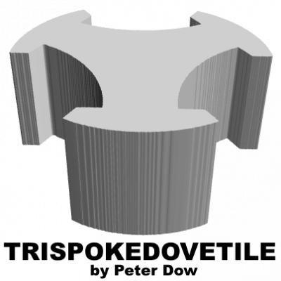
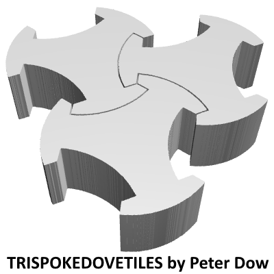
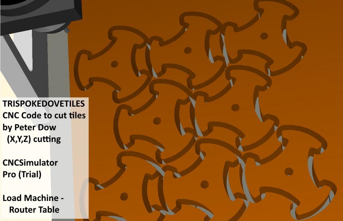
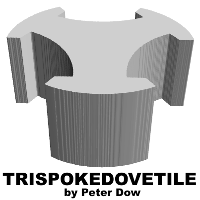
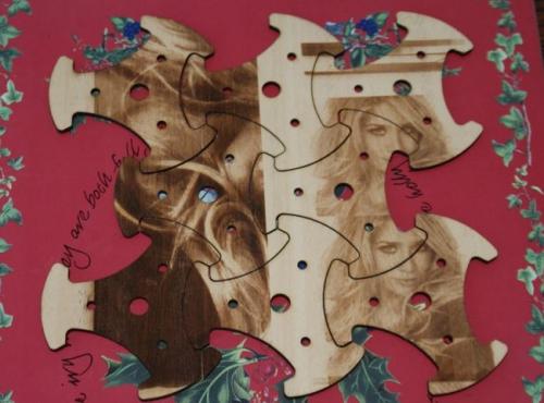
BEWARE BAD LINKS ABOVE! I lost my website hosting in January. I was not "hacked" but the gcehosting administrator seems to have gone out of business and the hosting company he was using (godaddy) is serving various spurious adverts whenever anyone clicks one of my old links. I have got the following pages back on-line with a different hosting company now so try these links. Trispokedovetiles: Three-spoke dovetailing tiles by Peter Dow Trispokedovetiles: CNC code to cut tiles by Peter Dow Trispokedovetiles Gallery I can't edit my earlier posts to correct the old links, sorry. I've not done anything with this project since January.
-
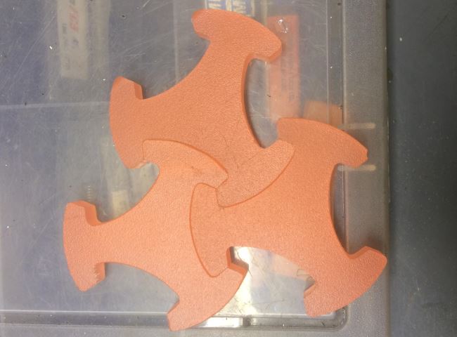
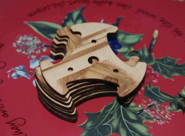
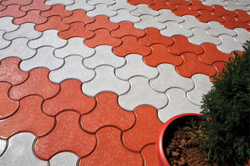
Thanks for expressing an interest tar. "If they interlock, shouldn't the shape cut out of an innie be exactly the same as the shape cut out around the outie? In other words, the pattern for cutting the tiles should have no waste." I don't follow you and don't want to invest the time to interrogate you to find out what you mean. It seems to be a unhelpful time-wasting conversational point in passing while you have no actual intention to cut any tiles yourself so I think I will pass on attempting to answer that one, sorry. I don't wish to brush all enquires off but I don't wish to give the impression that I welcome any opportunity to engage in idle chit-chat because I don't. However, if I have misunderstood and you or someone else has your own CNC cutter and really want to know how to cut some of these tiles then I would like to help that sort of genuine enquiry. "And the manufacture of this shape tile would be more readily done molding one tile at time from concrete, than cutting from a slab of stone of a certain thickness." A CNC cutter using my code could also be used to make a mould to make trispokedovetiles. "or are you using a jigsaw and having to account for the thickness of the blade? sorry, you said that it is a router path you are showing" Well the webpage offers 2 options according to whether you tick the "spaced" box or not 1. "spaced" unticked - cut tiles as assembled, assuming the kerf is narrow enough, as would be suitable for laser, plasma or water jet cuttting 2. "spaced" ticked - cut tiles separated, assuming a wider kerf, as would be suitable for router cutting "nice tiles" Thank you tar. I've now added a Trispokedovetiles Gallery webpage because I've got some real tiles cut now.


-
TRISPOKEDOVETILES ROUTER CUTTING My trispokedovetile CAD-CAM webpage now offers an (X,Y,Z) option for router cutting using rotary tool paths between spaced out tiles - I've simulated the CNC router code -


-
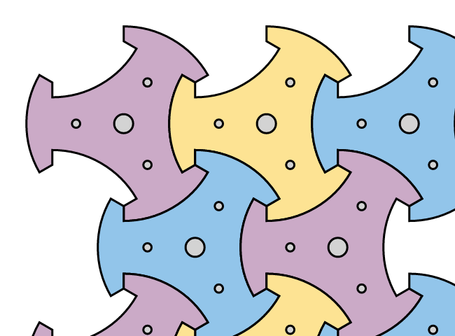
HOLES! Now cut trispokedovetiles by CNC laser cutter with (or without) HOLES!

-
For Computer-Aided Manufacturing of trispokedovetiles, I'm publishing today my new Javascript web-page - Trispokedovetiles: CNC code to cut tiles web-page G-code generator - which generates Computer Numerical Control (CNC) code which I've tested with CNC Simulator Pro but not on a real CNC cutter as yet.
-
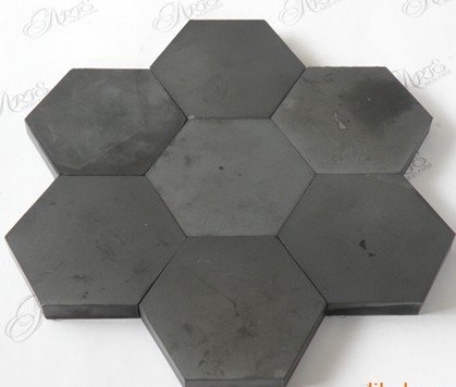
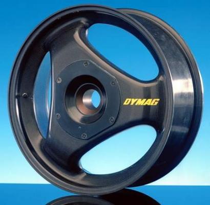
There's no "circular motion" nor "rotation" nor "wheel" movement intended. Think jigsaw puzzle pieces or interlocking paving tiles to remember that not all things which interlock are intended to rotate. I presume I have confused you with ... However, the similar shape is where the similarity begins and ends between a 3-spoke wheel and a trispokedovetile, which is a TILE not a "wheel" nor a "gear". I'm suggesting to use the shape for tiled armour - Hexagonal ceramic armour tiles - but tiled armour which interlocks.

-
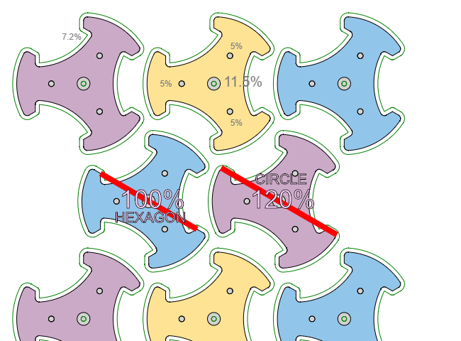
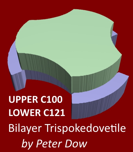
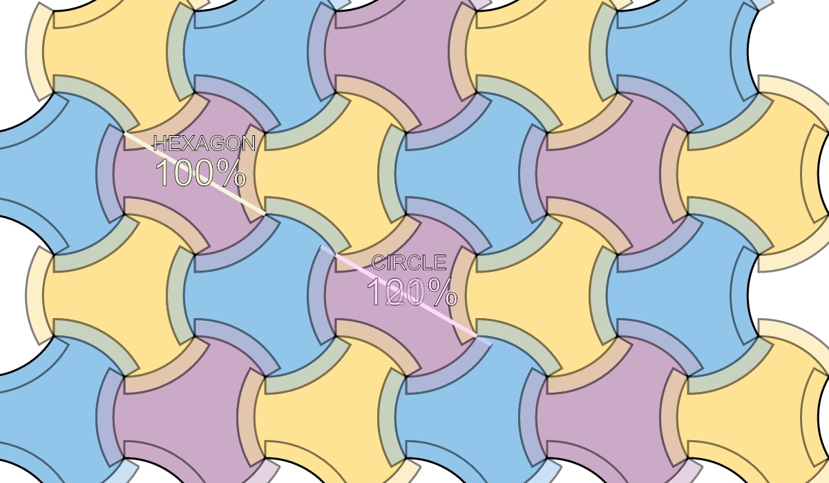
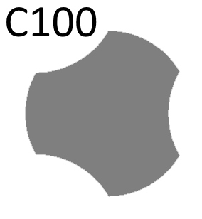
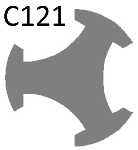
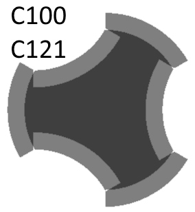
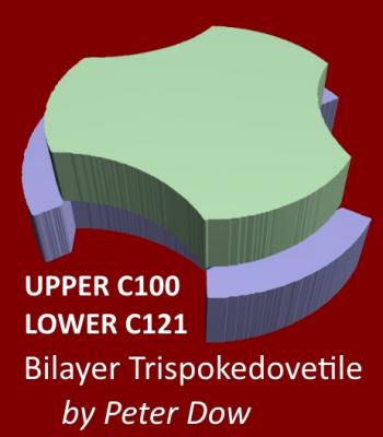
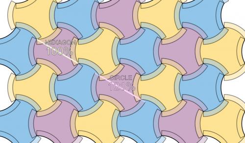
Now to consider the important issue of interlocking trispokedovetiles against movement in the direction normal to the tiled plane, which for the application of tiled armour would be the normal to the armour surface, in the direction of a bullet's path. BILAYER TRISPOKEDOVETILES I propose that the unit armour tile be comprised of 2 joined trispokedovetiles with matching HEXAGON parameters but each with a different CIRCLE percentage. For example, suppose we choose trispokedovetiles with CIRCLE = 100% and 121%. The reason for choosing C100 for the outer layer of the armour is because its 120 angle corners would be more robust. The reason for choosing C121 for the inner layer of the armour is because CIRCLE = 121% offers the largest percentage where the neck attaching the outer part rings is at least twice the thickness of the ring, attempting to balance the robustness of the ring parts to the robustness of the neck versus tensile stresses. Stacking and joining those together forms a bilayer trispokedovetile, "C100+C121". Drawing the 2 layers semi-transparently we can see how the bilayer trispokedovetiles would interlock in the normal to the plane. 2/3rds of the tiles can be slotted together, either the yellows and the blues or the yellows and the purples or the blues and the purples. However the final 1/3rd of the tiles would not simply slot in and would have be inserted by joining the two halves of the bilayer trispokedovetile in situ.

-
Tutorial on how to produce 3D images from my trispokedovetiles webpage A trispokedovetile in 3D 3 trispokedovetiles in 3D