Peter Dow
-
Posts
129 -
Joined
-
Last visited
Content Type
Profiles
Forums
Events
Everything posted by Peter Dow
-
 http://www.youtube.com/watch?v=asUa1PFix1A Video which illustrates the principle of using wind turbines and pumped storage hydro dam schemes together.
 -
Dam foundations and height of the dam above the bedrock The top of the Dow-Dam has an elevation of 780 metres by design. Image also hosted here The lowest elevation of the current ground surface of Coire Glas along the line of the proposed dam is 463 metres and subtracting 463 from 780 is how the initial value of 317 metres for the nominal height of the dam above the existing surface used in previous diagrams was arrived at. However, the glacial deposit of as yet unknown thickness is to be removed before building the foundations of the dam within and upon the bedrock. Although the lowest surface elevation along the line of the dam of the bedrock too is unknown a formula relating the Height of the Dam Above the Bedrock (HDAB) to the Glacial Deposit Depth (GDD) can be easily stated. HDAB = 317 + GDD Examples. If the GDD turns out to be 13 metres then the dam will be 330 metres tall. If the GDD turns out to be 83 metres then the dam will be 400 metres tall. Image also hosted here I propose that the height of the Dow-Dam be as tall above the bedrock as it needs to be to keep the top of the dam at an elevation of 780 metres no matter how deep the removed glacial deposit layer turns out to be. My approach may well differ from the SSE's approach. The SSE have said that their dam will be "92 metres" high and they may stick to that without having any goal for the elevation of the top of their dam. As the diagram indicates, I propose to secure the Dow-Dam to the bedrock by massive piles inserted and secured into shafts which would be drilled into the bedrock.

-
Geology of the Coire Glas site I have been able to extract this information from the British Geological Survey (BGS) Geology of Britain viewer, from the 1:50 000 scale map. Click to see larger image According to this map, the bedrock at the site which would be used to build the dam on top of and to extract rock from to create the tunnels for the underground complex seems to be a rock geologists call "psammite" which I understand to mean here "a metamorphic rock whose protolith was a sandstone". What neither the map nor the "psammite" name is telling us is how fractured the psammite rock there is and therefore how strong and also how impermeable or otherwise to water this rock is likely to prove to be, both of which would be interesting for any engineers building a pumped-storage hydro dam scheme there to know. What does look fairly obvious to me is that the superficial deposit of what the map calls "hummocky (moundy) glacial deposits - diamicton, sand and gravel" would not be strong enough, nor impermeable enough to build any dam on top of and at least along the line of the dam, this glacial deposit ought to be removed to get down to the bedrock within which to establish the foundations of the dam, although I would think that this glacial deposit might be made into aggregate to make the concrete for the dam by the sounds of it.

-
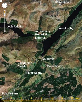
Loch Lochy and vicinity water flow control works Here is an annotated satellite photograph of the land south from Coire Glas showing Loch Lochy, Loch Arkaig, the isthmus between the lochs, Mucomir where Loch Lochy empties into the River Spean before it flows on as the River Lochy, the Caledonian Canal and Fort William where the river flows into a sea loch. Click to see larger image New waterway Loch Lochy is separated from a neighbouring loch, Loch Arkaig, by a 2 km wide isthmus, which I have identified on this map as "the Achnacarry Bunarkaig isthmus", after the local place names. It ought to be quite straight forward to build a canal or culvert, to connect those two lochs. The idea is that the new waterway would be wide and deep enough, enough of a cross section area under water, perhaps hundreds of square metres, so as to allow free flow from one loch to the other, so as to equalise the surface elevations of the two lochs, so as to increase the effective surface area of Loch Lochy so as to decrease the depth changes to Loch Lochy when water flows in from the Coire Glas reservoir when it discharges water when supplying power. Now, Loch Arkaig has a natural surface elevation of 43 metres and this would be lowered to that of Loch Lochy. The surface area of Loch Arkaig is given by wikipedia as 16 km^2 also, (though it looks to me somewhat smaller than Loch Lochy). In addition, partially draining Loch Arkaig to bring its level down to that of Loch Lochy will also reduce its surface area. If say, the additional surface area of Loch Arkaig is about 10 km^2 added to Loch Lochy's 16 km^2 this would give an effective surface area of 26 km^2 and reduce the potential depth variation to Potential depth variation of Loch Lochy + Loch Arkaig = 400 000 000 m^3 / 26 000 000 m^2 = 15.3 metres. Without equalising the loch levels, the depth changes to Loch Lochy that would require to be managed may be potentially more like 25 metres than 15 metres. So the new waterway is an important part of the new water flow control works that Coire Glas/Dow requires to be constructed. Additional Loch Lochy water level control measures When the Coire Glas reservoir is full, then the water level of Loch Lochy should be prevented, by new water works - drains, dams, flood barriers etc. - from rising due to rainfall and natural flow into the loch above a safe level which allows for the reservoir to empty into the loch without overflowing and flooding. The safe "upper-reservoir-full" loch level will likely turn out to be around about 15 metres below the maximum loch level. The next diagram showing the new loch drain and the reservoir pump inlets indicates how this might be achieved. Click to see larger image The drain from Loch Lochy to the sea which goes underground from the 14 m elevation level in the loch would need capacity for the usual outflow from Loch Lochy which currently goes through the Mucomir hydroelectric station. I have estimated the flow through Mucomir from its maximum power of 2MegaWatts and its head of 7m as somewhere near 0.2 Mega-cubic-metres-per-hour and compared that value using a spreadsheet I have written to predict the capacity of water flow through different sizes of drains using the empirical Manning formula and this is also useful for determining the appropriate size of the new water channel between the lochs. Ease my quantity To construct Coire Glas/Dow/600GW.Hrs/12GW may cost of the order of around £20 billion, but that would be my order of magnitude educated guess more than a professional cost estimate. In other words, I'm only really confident at this early "vision" stage that the cost would be closer to £20 billion than it would be to £2 billion or to £200 billion but I'm not claiming to be able to quote an accurate cost estimate at this stage. I have not itemised my costs - how much for land, how much for labour, how much for trucks, how much for diggers, how much for cement, how much to install the generators etc. and the SSE have not published itemised costs for theirs either so I can't calculate my costs in a proportion to the SSE's costs. Although my version offers 600 GigaWatt-Hours energy and 12 GigaWatts power (or 20 times the capacity and performance) some of the items in my version would cost more than "in proportion", in other words more than 20 times the SSE's cost. For example, the cost of my dam will be more like 27 times the cost of the SSE's dam. (3.44 times higher and thicker and 2.27 times longer). For example, the cost of excavating 400 million tonnes of rock from the reservoir bed to increase the capacity of the reservoir to hold water (and energy) in my version won't be in proportion to the SSE costs for excavating their reservoir bed because, as far as I know, they don't plan to excavate their reservoir bed at all. On the other hand, my land costs are about the same as the SSE's - much less than in proportion. I may well need to use more land to dispose of the additional excavated rock spoil but perhaps when that additional land has been landscaped over it could be resold? So it depends how much the land is as a proportion of the SSE's costs. If land is a small part of their costs, if 20 similar sites to build on are just as cheap and easy to buy then my costs will be much more than proportional, since saving land won't save much money. If land is scare and valuable and the cost to purchase suitable land with a good chance to get permission to build on it is a significant proportion of the SSE's or anyone's costs to build 20 of their size of hydro dam schemes then my costs may be better than proportional. Sometimes securing suitable land for development can be very problematic, very expensive. Sometimes people won't sell their land. Sometimes the authorities won't agree that the land can be used in this way. The SSE say that suitable sites for such pumped storage schemes are rare indeed, so land costs may be very significant and my scheme good value for money. If indeed the cost of my scheme is somewhere around £20 billion it is likely to cost far more than the SSE or any electrical power supply company looking to their annual profits for the next few years could possibly afford. Something like £20 billion I expect could only be found as a national public infrastructure project, spending government money, like the building of a large bridge or motorway would be. A £20 billion government project would require Treasury approval, at least while Scotland is ruled as part of the UK. I have suggested funding my much larger hydro dam scheme by re-allocating of some of the Bank of England's "Quantitative Easing" funds which amount to some £300 billion of new money printed with not much to show for it.
-
I need to update my estimates for the energy stored by my scheme. Now I'm thinking 20 times more energy could be stored than the SSE plan offers. It now looks like 600 Giga-Watt-Hours is achievable! My dam is more like 3.44 times higher not just "3 times" higher than SSE's dam. My dam is more like 2.27 times longer not just "2 times" longer than SSE's dam. A greater percentage of the water in my reservoir achieves maximum depth because of the excavated reservoir bed. My calculations indicate that the volume of water in my reservoir when full would be about 400 million cubic metres and its centre of mass would be 569 metres above the lower reservoir which gives a theoretical potential energy in excess of 600 GW-Hrs! Now allowing for turbine efficiency of 90% but remembering that more rock could be excavated perhaps around the perimeter to further increase water volume then it is possible that a genuine 600 GW-Hours could be available as supplied power at Coire Glas! My bigger plan for Coire Glas offers about 20 times more energy stored, than the SSE's plan of only 30 GW-Hrs. 600 GW-hours is enough for 100 hours of supply at 6 GW - keeping the lights on in Scotland, using only renewable energy. See this power-flow map for Britain I found recently which gives peak power flows and I assume the figures are MegaWatts. Power flow map source - National Grid. Effect on Power Transfers But a 600 GW-hr energy store at Coire Glas could also supply 8.5 GW for 70 hours or 12 GW for 50 hours - and that would be very useful too, for two reasons. 1. Providing an energy store for the grid in England. 2. Providing more heat energy in Scotland from renewables as well, so that we can offer consumers a cheaper alternative to gas, coal and oil heating of homes, offices etc. For those two reasons, I would install 12 GW generators and transmission capacity for my Coire Glas hydro scheme alone. After my Coire Glas project next we'd have the option of building a few more pumped-storage schemes the size of my plan for Coire Glas and then Scotland could provide energy storage facilities - Either for all of the "British national" grid Or to make profits for an independent Scottish economy by energy import/export. Whatever the politics, Scotland has the geography to site pumped storage hydro dam schemes to supply renewable energy 100% of the time. The investment required can come from re-allocating Bank of England "quantitative easing" cash and this is the way to go to get 100% renewable energy supplied under all circumstances. I need to update that too. My dam would be 3.44 times as high and as thick, 11.8 times the cross-sectional area, 2.27 times as long so about 27 times the volume, the mass and the cost. It turns out the additional flows to and from the Loch is a much bigger issue than I first thought. The volume in the dam is more than I thought and the surface area of Loch Lochy is less than I had assumed, only some 16 kilometres squared. This means I'd need the top 25 metres of water (at least) from the Loch to fill my dam! Hmm.
-
What's not to like about it? I like spending money on something worthwhile like a big hydro scheme whereas I dislike the government wasting good public money on stupid bankers like this. As I said to CaptainPanic. I don't need a geological map at the early stage of presenting a vision for building a dam and excavating a reservoir bed. I think it reasonable to assume that the geology would be favourable for my scheme since the SSE have determined that the geology is favourable for their scheme on the same site. I did clearly say in an earlier post that my vision for the excavated reservoir bed considered both the case of very stable bed rock and unstable ground. Remember? And in a later post I illustrated the options for the reservoir perimeter wall - vertical, sloping at 45 degrees or somewhere in between with a diagram. I hope that is clear now.
-
Well without measuring the vertical surface areas I would estimate that a dam more than 3 times higher and twice as wide would be at least 6 times greater surface area. No, I would expect a dam 3 times as high to be 3 times as thick, so the transverse cross-section would be 9 times the area. So then a dam twice as long would be 2 x 9 = 18 times the volume, 18 times the mass, 18 times the cost. Loch Lochy. "Loch" is Scottish for "lake". There are many lochs in Scotland and the nearest one to Coire Glas happens to be called "Loch Lochy" which will be used as the lower reservoir for the SSE scheme and for my scheme though the additional volume of water in my scheme might require additional work on the Loch to facilitate the additional flows. Nice. Well here is an enhanced satellite photograph which will help to identify the geology of interest. Enhanced satellite photograph Image also hosted on PostImage.Org From what you are saying Michel, it sounds like you have not looked at the site using Google Earth which provides a three dimensional view you can move around in, zooming in, rotating, very much like a video game. It is a very impressive tool. I might be posting a video in future showing some views from Google Earth for those who can't manage to get it to work. I suggest you have a good look if you can. I gave the Google Earth link for the site in my original post but here it is again. Google Earth 3-D Coire Glas
-
Ah. How's this? Cross section of the Dow-dam The Dow-dam is more than 3 times higher than the SSE-dam. A horizontal line one third of the way up the Dow-dam indicates the relative height of the SSE dam although it is not aligned with this cross-section. Image also hosted on PostImage.Org Maps showing the line of cross-section viewed from each side Image also hosted on PostImage.Org Image also hosted on PostImage.Org I'll answer your other points after I get some sleep.
-
Well the Bank of England is finding it very easy it seems to hand out free cash ("investment" is not quite the right word) to banks to try to breathe life into a UK stalled economy with plenty of spare productive capacity and high unemployment. Now instead of wasting that on banker's bonuses and their jet-set life-style, I'll take oh £20 billion or so of government money to build this pumped-storage hydroelectric dam and there will be something to show for the money that will be of use not just in 10 years but for future generations. Well my scheme won't solve all future problems but it helps more than the SSE scheme which in future will look like a missed opportunity because it occupies a site that could produce so much more. My scheme is one step, it is just that it is a bigger, better step than the SSE scheme. This is the site up for public consultation. This is the time when a better plan for this site can be considered. Otherwise the SSE plan will be the only option for Coire Glas on the table. The fair maiden Coire Glas is at the altar with her SSE suitor. So this is the time "to speak now or forever hold your peace".
-
Unavailable, yes, (too intense, no comment). That's the general idea. SSE say about 30 giga-Watt-hours of energy stored and they intend a 0.6 giga-Watts generator, and 30 / 0.6 = 50 hours, so twice your "24h" comfortably. My point is that 0.6 gW is much less than the currently installed wind-power in Britain which is about 6gW. There is a need for more power and therefore a bigger reservoir than the SSE plan now and even more so in future. Someone is always going to have a negative reaction. Name me one project ever that someone didn't have a negative reaction to. Define "out of size". It is as big as it needs to be. Yes I did mention that in my original post. I am working with the dimensions of the site which the SSE plan to use. I don't have a free choice of sites or land which I can flood. If I propose to flood land other than than the land the SSE plan to flood this is will not even be considered seriously coming from an independent author like myself. That is an excellent idea. Thank you. Cross section of the Dow-dam reservoir Cross section along the major diameter of the elliptical excavation of the reservoir bed Also hosted on PostImage.org
-
Sure wind power is the favourite for planned future investment in renewable energy generating capacity. You mean when the wind isn't blowing in the south / north but it is blowing in the north / south then the grid can distribute power to where it is to where it is needed? Sure that goes without saying but there are going to be many days when the wind isn't blowing appreciably anywhere on mainland Britain and that's when you need to have stored energy available, or else you'll be forced to fire up your back-ups, gas / coal / nuclear / whatever. Oh, we've used the same reference. That'll cut down on the arguments then. And when future installed wind power capacity goes up to 33-35 GigaWatts then the SSE plan will last less than one hour before you are reaching for the start up button for the back-ups. Sure if we want to burn fossil fuels or use nuclear then we can but we don't want to - we want to use renewable sources only. Well right now, my 6 times the SSE's 30 GWhrs would be 180 Gigawatt-hours which would last a respectable 180 / 6 = 30 hours compensating for all current wind capacity when becalmed but as wind generating capacity rises to 33-35 GWhrs then we are back to 180 / 34 = 5.5 hours, useful but by no means enough for weather patterns that tend to stick around for days at a time. OK I think you are concentrating on the current needs for storage but you need to look to the future of wind power. Perhaps if I may quote a recent email I wrote explaining the strategic needs in the future. Scotland best for pumped-storage hydroelectricity energy economy This is a statement of the obvious as far as Scottish electrical power-generation engineers and scientists are concerned I expect but I am making this statement anyway, not for the benefit of our scientists or engineers but to inform the political debate about the potential of the Scottish economy "after the North Sea oil runs out" because political debate involves mostly non-scientists and non-engineers who need to have such things explained to them. The Scottish economy has a profitable living to make in future in the business of electrical energy import/export from/to English electrical power suppliers and perhaps even to countries further away one day. The tried and tested engineering technology we Scots can use in future to make money is pumped-storage hydroelectricity. Wikipedia: Pumped-storage hydroelectricity "The technique is currently the most cost-effective means of storing large amounts of electrical energy on an operating basis, but capital costs and the presence of appropriate geography are critical decision factors." In Scotland, the Cruachan Dam pumped-storage hydroelectric power station was first operational in 1966 and was built there to take advantage of Scotland's appropriate geography and available capital. So Scotland has the appropriate geography for pumped-storage hydroelectric power and we have the capital particularly if we invest some of the taxes on North Sea oil before it all runs out and it is all spent. Investment in wind-power energy generation is proceeding apace, in Scotland, in England, on and offshore, and that's very "green" and quite clever, though wind power is not as dependable as tidal power, but unless and until sufficient capacity to store energy becomes available to supply needs when the wind isn't blowing then conventional, and perhaps increasingly expensive, coal, gas or oil burning or nuclear energy power will still be needed to keep the lights on when the wind doesn't blow. Scottish opportunity Here is the opportunity for the Scottish economy in a future where wind-power generation is increasingly rampant: if we Scots build a large capacity of new pumped-storage hydroelectric power stations, not only can we supply all our own Scottish energy needs from "green" renewable energy schemes, but we could provide energy storage capacity for customers outside Scotland, particularly in England, who live in a land not so well endowed with appropriate geography for hydroelectric power. In future, a Scotland with investment in a massive pumped-storage hydroelectric capacity could buy cheap English wind-power while the wind is blowing then sell the same energy back to English power suppliers, at a profit, when the wind isn't blowing and the English will pay more for energy. So everyone wins, the energy is all green, the electricity supply is always available when it is needed and that is how the Scottish energy economy does very well after the North Sea oil runs out. So problem solved but not job done as yet. We Scots do actually need to get busy investing and building pumped-storage hydroelectric power generation and supply capacity in Scotland now.
-
Thank you. Yes it is worth it. Yes excavating the reservoir bed is worth it. All the additional energy storage capacity created by excavating the reservoir bed will be utilised and indeed much more storage capacity will be needed requiring additional reservoirs and dams. The simple answer is "yes". The smaller dam proposed by the SSE only stores about 30 Gigawatt hours and they will only be able to supply say their planned 0.6 Gigawatts for 50 hours before the dam empties. Now 0.6 gigawatts is not to be sneezed at but it is insufficient by a long way to supply all the power needs. If you want some figures then here are some for Britain as a whole which has an integrated electricity supply grid. So it is clear that 30 giga-watt-hours could supply British 63 giga-watts for about half an hour. Now if my proposed far larger dam stored 6 times the energy (twice the area and 3 times the depth of water equals 6 times the volume of water) that would still only be 3 hours supply at 63 gigawatts and the wind is becalmed for far longer than that. So there is no risk that this will be too big. There is a certainty that it will not be enough but it is a start. The reason for building bigger while we are at it is to make an efficient use of the site because there will be a limited number of suitable sites and if the site is used up with a smaller dam then that is a possible opportunity to increase capacity lost. Image also hosted on postimage
-
I am presenting here my vision for a large pumped storage hydroelectric 2-square kilometres surface-area reservoir and 300+ metre tall dam which I have designed for the Coire Glas site, Scotland. (View site using Google Earth where the convenient label is "Loch a' Choire Ghlais" - or, http://tinyurl.com/coireglas) I was inspired to conceive and to publish my vision by learning of the Scottish and Southern Energy (SSE) proposal to build a smaller hydroelectric pumped-storage scheme at Coire Glas which has been presented to the Scottish government for public consultation. I have not long been aware of the SSE plan for the Coire Glas scheme, not being a follower of such matters routinely, but I was prompted by an earlier tangentially-related news story (about energy storage technology for renewable energy generators such as wind farms) to write to Members of the Scottish Parliament on the merits and urgency of new pumped storage hydroelectric power for Scotland on 14th February and a reply from Ian Anderson, the parliamentary manager for Dave Thomson MSP received the next day, the 15th February informed me about the SSE plan and Ian added "initially scoped at 600MW but, to quote SSE, could be bigger!" I replied to Ian "So the schemes proposed by the SSE are welcome and ought to be green-lighted and fast-tracked, but I am really proposing that Scots start thinking long term about an order of magnitude and more greater investment in pumped storage hydroelectric capacity than those SSE plans." So I had in mind "bigger would be better" but it was not until the next day on the 16th February when a news story informed me that the SSE plans had been submitted to the Scottish government for public consultation that I thought "this needs consideration now". So starting late on the night of the 17th, early 18th February and all through the weekend, I got busy, outlining my alternative vision for a far bigger dam and reservoir at the same location. So this is my vision as inspired by the SSE plan. If my vision is flawed then the fault is mine alone. If my vision is brilliant, then the brilliance too is mine. Image also hosted on postimage The black contour line at 550 metres elevation shows the outline of the SSE proposed reservoir of about 1 square kilometre surface-area and the grey thick line shows the position of the proposed SSE dam which would stand 92 metres tall and would be the tallest dam in Scotland and indeed Britain to date though it seems our dams are several times smaller than the tallest dams elsewhere in the world these days. Part of the red contour line at 775 metres elevation, where the red line surrounds a blue shaded area, blue representing water, shows the outline of my larger reservoir of about 2 square kilometres surface-area and the thicker brown line shows the position of my proposed dam which would stand 317 metres tall which would be one of the tallest man-made dams in the world. Excavated Reservoir Bed The green ellipse of major diameter of 1.5 kilometres and minor diameter of 1 kilometre represents an excavated reservoir bed, as flat and as horizontal as practical, at an elevation of 463 metres. Since an excavated reservoir bed is not, that I can see, part of the SSE plan, at any size, I will provide some more information about my vision for that now. The basic idea of excavating a flat or flattish reservoir bed is to increase the volume of the water stored in the reservoir because more water means more energy can be stored. Depending on the geology and strength of the rock of Coire Glas the walls of the reservoir bed perimeter could be as steep as vertical from the reservoir bed up to the natural elevation of the existing rock surface which would mean, presumably, blasting out rock to create a cliff which at places could be as much as about 290 metres tall. Near the dam, the reservoir bed perimeter wall would be only 40 metres or less tall. The further from the dam, the higher the wall will be and the more rock needs to be excavated. A vertical reservoir bed perimeter wall would be ideal to maximise reservoir volume wherever the geology provides a strong stone which can maintain a vertical wall face without collapse, (a stone such as granite perhaps). Where the geology only provides a weaker stone then a sloping perimeter wall at a suitable angle of repose for reliable stability would be constructed. So the reservoir perimeter wall could be as sloped as shallow as 45 degrees from the natural elevation at the perimeter of the eclipse sloping down to the reservoir bed at 463 metres elevation in the case of the weakest and most prone to collapse kinds of stone. Exactly how strong the stone is at each location I guess we'll only find out absolutely for sure if and when engineers start blasting it and testing the revealed rock wall face for strength. The shape of the perimeter of the excavated reservoir bed is not absolutely critical. So long as it ends up as a stable wall or slope, however it is shaped by the blasting, it will be fine. There is no need to have stone masons chip the perimeter smooth and flat! The ellipse is simply the easiest approximate mathematical shape to describe and to draw. If the end result is not a perfect ellipse, don't worry, it will be fine! OK, well I guess that's the vision part over. The rest is fairly straight-forward engineering I hope. Oh, and there is always getting the permission and the funding to build it of course which is never easy for anything this big. OK, well if anyone has any questions or points to make about my vision or can say why they think the SSE plan is better than mine, or if you don't see why we need any pumped storage hydroelectric scheme at Coire Glas, whatever your point of view, if you have something to add in reply, please do.
-
A discussion on wikipedia on the boiling point of gallium seems to indicate that the CRC handbook editions list the following values for the boiling point of gallium - 47th to the 66th editions - 2403°C 84th and later editions - 2204 °C Perhaps D H will finally tell me the edition number of his CRC handbook he quoted from above? My suggestions as to why measured boiling points vary so much Superheating of the liquid We know that gallium supercools readily so why cannot it also superheat? Perhaps experimenters are in too much of a hurry to measure the boiling temperature and keep raising the temperature too quickly without waiting for the superheated liquid to boil which it will do eventually at a lower temperature? Differences in pressure If anything genuinely changes a boiling point temperature it is pressure. Perhaps experiments have not taken care to ensure the heated liquid is under standard pressure conditions? Simple experimental error Temperature measuring devices may have been wrongly calibrated or misread? Chemical contamination of the sample Gallium is considered to be very reactive at high temperature. Perhaps the samples are reacting with the vessel and the contaminants are modifying the boiling temperature? Start here - http://en.wikipedia.org/wiki/Temperature_measurement Galinstan, an alloy of gallium, indium and tin, is a non-poisonous mercury-substitute for thermometers. The glass of the thermometer would melt before galinstan boils or dissociates. Galinstan is a much "cooler" liquid metal than mercury. B) For measuring the sort of temperatures under discussion here (2000 plus degrees C) perhaps a pyrometer of some kind.
-
Well you cared enough to post in this topic, for which I thank you. I wonder if you could have a look for a second table in your CRC handbook which also gives (different) values for boiling points of the elements. Perhaps there is a "chemistry" table and a "physics" table? Is there? If not which edition is your CRC handbook?
-
Your CRC handbook values seem to agree exactly with the Penguin Dictionary of Chemistry therefore one may be copying the other or both using the same source. Wikipedia have a page where they name references for boiling points. However, the data values tabulated on that wikipedia page do not seem always to have been copied accurately from the reference sources. There is an associated discussion page wherein I am pointing some of this out to wikipedia editors. Well here is a curious thing. A chap on wikipedia says he has checked his 89th edition of the CRC handbook of chemistry and physics and he says that it states "2204 degrees C (2477 K)" for the boiling point of gallium. So I am wondering if you, D H, are looking at a different table in the same book? I have already pointed out that Kaye and Laby gives two different values for the same property in two different tables. What is the heading and section number of the table in the CRC handbook from which you are reading "2270°C for tin, 2403°C for gallium" from? Or perhaps your edition of the CRC handbook is not the 89th but a different edition and the value has changed between editions? Can you, or anyone, help to clear this up please?
-
CRC claim tin boils at a lower temperature than gallium?! Another source derived from an old publication I remember being on the same shelves as the CRC handbook back in the days when I used the library is NPL's Kaye and Laby which gives 2620°C for Tin and 2200°C for Gallium but most of their temperatures they only quote to the nearest 10°C. Temperatures at the boiling point depend on pressure so if the temperature is measured while the metal or whatever is boiling in an enclosed vessel this would effect the boiling point temperature. However, the pressure is not specified most often and I am left to guess that it might be atmospheric pressure. I appreciate that. For example, maybe the author or publisher for "Chemistry, Molecules, Matter and Change" book swapped the 7 & 2 around and put in "2720°C" instead of "2270°C" which seems to be a more popular value? I have raised the matter on the Wikipedia discussion pages for Tin and Gallium so we will see what Wikipedia has to say for themselves on this in due course perhaps. It would be nice if there was a definitive source for the world scientific and engineering community, an organisation which prides itself on knowing it has the right values and referenced chapter and verse of all those had measured the value and how. There are a lot of websites out there, science-for-the-people websites, but with advertising on them, which are very happy to quote a value for this or that without themselves having any knowledge of how and where the value is derived. These sites are copying the information from somewhere, anywhere, sticking an advert on their page to make some money yet not being all that useful in reality. However, in this case, the values in books I remember reading long before the internet was around seem to disagree significantly on these boiling temperature values as well. Kaye and Laby does not even agree with itself between one table and another, especially for Tin though the values for Gallium are close enough. In another table, Kaye & Laby. 3.10.1 Standard molar heat capacities and properties of melting and evaporation of the elements they quote a normal boiling temperature Tvap for Tin (Sn) of 2990K which I make 2717°C and for Gallium (Ga) 2480K which I make 2207°C which is different from the their table 3.1.2 Properties of the elements value for Tin of 2620°C and for Gallium 2200°C. I heard that some elements and chemicals exhibit dynamic supercooling / superheating phenomena but I had not heard that there wasn't always a definitive temperature which defines a stable phase transition. I see a mess in the assortment of published data but I am more likely to attribute that mess to us scientists doing a less than perfect job rather than to matter not being sure at what temperature it wants to boil at. Well if you are interested I was drawing a bar chart with the temperature of the liquid phase for the elements of galinstan. This is what I have got so far based on the wikipedia values. There seems to be little data available regarding the boiling point or dissociation temperature of galinstan but before I can consider that question properly I need to consider why the published values for the boiling points of Tin and Gallium vary from one source to another. Hmm but then many professions do not use the CRC handbook I suppose. In any case, I have never assumed that what "professionals" do routinely should just be accepted without challenge. As scientists we seek the truth not to follow the crowd.
-
I have noted big disagreements of a scale of hundreds of degrees centigrade in published values for the boiling temperature of chemical elements such as tin and gallium. For example, Tin Wikipedia - 2602 °C, 2875 K, Chemical Elements website - 2270.0°C, 2543.15 K which agrees with one of my text books Penguin Dictionary of Chemistry - 2270°C but not the other Chemistry, Molecules, Matter and Change - 2720°C Gallium Wikipedia - 2204 °C, 2477 K, Chemical Elements website 2403.0 °C, 2676.15 K which agrees with one of my text books Penguin Dictionary of Chemistry - 2403 °C but not the other Chemistry, Molecules, Matter and Change - 2070 °C Of course I am wondering why the different values - errors by the authors of books or websites or genuine disagreements between scientists as to the values? Which source do people recommend as the most reliable source of accurate boiling temperature information and why?
-
The catamaran tank - an MRAP which doesn't roll over!
Peter Dow replied to Peter Dow's topic in Engineering
Introducing HUMPBAC - an armoured personnel carrier with a connecting doorway from the rear of the vehicle to walk through into the armoured passenger trailer. Tickets please! HUMPBAC Hinged Under-floor-Mine-Protection Battle-ready Armoured-personnel Carrier Copyright © Peter Dow, 7th August, 2010. HUMPBAC Features Trailer bolts firmly to the rim of the vehicle forming a rigid joint Rear section of vehicle is hinged to articulate the trailer's vertical motion Movement of hinged rear section accommodated by a hump in the roof Vehicle rear door can serve as a connecting doorway to the trailer section Front vehicle seats a maximum of 11 people Armoured passenger trailer seats a maximum of 7 people Vehicle with trailer seats a maximum of 18 people Roof mounted remote-controlled machine guns- front, top & tail gun Trailer wheel steering 6-wheel drive Telescopic Rear Axle & Wheels Rotation on the spot Even axle weight distribution 5 : 3 weight & length ratio, 5 (vehicle) : 3 (trailer) -
The catamaran tank - an MRAP which doesn't roll over!
Peter Dow replied to Peter Dow's topic in Engineering
Here is an idea. If you need to, please review this diagram of a steering mechanism from Wikipedia on Steering. OK my idea is you replace parts of the steering rod with pneumatic pistons, either side of the connection to the steering column as follows. There is an air tank topped up by an air pump which when its valve is turned on inflates the pneumatic pistons now integral to the steering rod. (This should only ever be done while the vehicle is at rest and the driver has selected clockwise or anti-clockwise gear - some kind of safety cut out.) The air pressure quickly rises (that is why you use air, not hydraulics, it is so much faster if you supply from an air pressure reservoir - there is not a need for huge force, just speed, so pneumatics is the driver of choice I think) and when the air pressure exceeds a critical amount, retaining catches, which normally hold the pistons firmly closed against all manner of road bumps, suddenly break open and the pressurised air forces the pistons open against a spring and the steering rod lengthens to a maximum and the wheels are turned inwards to their respective stops - hard right hand turn for the left hand wheel and hard left hand turn for the right hand wheel, ready for rotation. It is clear to me that the 45-50 degrees or so maximum turning angle normally is limited by the steering rod at full stretch - not by the wheel bumping into the axle - so 75 degrees in this diagram looks easy. When you want to revert to normal steering, the system simply releases the air pressure in the pistons and the pistons close with the spring and the pistons snap shut into their retaining catches ready for normal steering. As you can see this is for rotation about a point mid-way between the rear axle. It is only when I add on my trailer to my armoured personnel carrier that the vehicle does zero turning radius, strictly speaking. Hence I have always called it "rotation on the spot". So do you think that would work? I would doubt that is the way that lawnmowers do zero turning radius. -
The catamaran tank - an MRAP which doesn't roll over!
Peter Dow replied to Peter Dow's topic in Engineering
Telescopic rear axle armoured vehicle - easy! OK well I have to admit there are a few problems with my CATAMARAN vehicle design. Heavier armour for the same volume protected The inner sides required to be armoured and connected together and that all adds weight. Precisely how much more weight is difficult to predict but a significant thickness of additional armour required certainly Therefore I am now turning to a different and easier idea to solve the roll-over problem for MRAP armoured vehicles - telescopic rear axles. Telescopic Rear Axles. Extended - Wide. Telescopic Rear Axles. Collapsed - Narrow. Hydraulic cylinders components are available to be adapted for this purpose. The axles would need to be braced vertically to stop them bending under the weight of the vehicle. Certain design concepts I have previously described for the CATAMARAN vehicle which I do want to retain for the telescopic rear axle design, such as Trailer wheel steering Armoured passenger trailer Rotation on the spot Roof mounted remote-controlled machine guns 5 : 3 ratio, 5 (vehicle) : 3 (trailer), weight and length distribution Therefore the telescopic rear axle design although it is perhaps a less radical and innovative mono-hull design than the CATAMARAN Vehicle design, nevertheless it has many excellent features which greatly enhance the performance over the standard MRAP. So I await with interest to see if anyone can identify flaws with my second major design iteration. -
The catamaran tank - an MRAP which doesn't roll over!
Peter Dow replied to Peter Dow's topic in Engineering
The CATAMARAN Vehicle vs. the MRAP. Which is better? Compare and contrast the features of the CATAMARAN Vehicle against the MRAP it is designed to replace. The CATAMARAN vehicle is not taller than an MRAP with a gun turret. Yes the CATAMARAN vehicle will be taller including the height of its guns than an MRAP without a gun turret but the CATAMARAN vehicle's automatic guns are quite light and don't raise the height of the centre of gravity much and maybe has a lower centre of gravity than an MRAP with a gun turret with armour and gunner up top as well. The CATAMARAN vehicle can be the same width as an MRAP when configured narrow, such as Y1Y at 9 feet wide. It can be narrower, the same width or wider than a tank to suit the roads or terrain. The CATAMARAN vehicle will be as fast as an MRAP without the trailer on a straight road. It will be much faster off road, with or without trailer, because it won't roll over and a rolled over MRAP is a slow as you can get; you'd be faster on a donkey! The CATAMARAN vehicle will be as well armoured as an MRAP. The CATAMARAN vehicle will have as much internal cargo space without the trailer and more internal cargo space with the trailer compared to an MRAP. The CATAMARAN vehicle offers the possibility, depending on the width configuration, of additional external cargo space by strapping certain loads, which don't require armoured protection, to the connecting bars in between the two halves of the vehicle. The CATAMARAN vehicle will very manoeuvrable even with the trailer attached so its length is no big deal. The CATAMARAN vehicle will have more firepower than an MRAP. Two roof mounted machine guns without the trailer, 4 guns with the trailer. The CATAMARAN vehicle is "ambush repellent". whereas the MRAP is only "ambush protected". Terrorists going up against a CATAMARAN vehicle with RPGs and the like is a more risky proposition for them because the defenders have got 2 or 4 pairs of eyes watching for ambushes with their fingers on triggers to fight the attackers off. Conclusion The CATAMARAN vehicle is a better vehicle than MRAPs for any conflict where MRAPs are now the vehicle of choice. CATAMARAN Vehicle & trailer - 6 machine guns, 16 seats! The image shows some vital statistics for my proposed CATAMARAN vehicle, only one Y-side is pictured. The front powered and driven vehicle seats a maximum of 10, 5 in either Y-side. Each side seats 5 = 1 - one driver or reserve driver or front passenger + 2 - one front gunner and one rear gunner + 2 - two passengers The trailer seats a maximum of 6, 3 in either Y-side Each side seats 3 = 2 - two passengers + 1 - one tail gunner So the vehicle with trailer attached seats a maximum of 16, 8 in either Y-side. Each side seats 8 = 1 - one driver or reserve driver or front passenger + 3 - one front gunner, one rear gunner and one tail gunner + 4 - four passengers. The driver can be either on the left or on the right Y-side and then the reserve driver or front passenger would be on the right or left Y-side, respectively. Weight distribution The image also shows the ideal weight distribution in relation to the axles. Each square represents the same weight and length which is one eighth of the weight and length of the combined vehicle with trailer, one fifth of the weight and length of the front powered and driven vehicle and one third of the weight and length of the trailer. Designing the vehicle to have this weight distribution helps to keep the vehicle well balanced in terms of equal weights over each axle which allows for the same suspension and tyres to be used through-out and maintains this balance with or without the trailer attached. -
The catamaran tank - an MRAP which doesn't roll over!
Peter Dow replied to Peter Dow's topic in Engineering
MRAP I think has better mine resistance than many APCs and possibly some lighter AFVs as well. MRAP is optimised to counter mines. MRAP is probably not as good against missiles as those other armoured vehicles but it was IEDs that were killing most in Iraq and Afghanistan so mines were the threat to counter and mine-resistant vehicles were the way the military decided to go. See later for my strategic ideas. The Stryker doesn't have the mine resistance ability of the MRAP I am guessing otherwise why this? Note "shallow" - it may have to be shallow because maybe Stryker does not have room for a deeper V-shape? Stryker does have some nice features though. Like that sloping front armour. Future MRAPs and my CATAMARAN vehicle could have sloping front armour too, perhaps shaped as a bow of a ship? Puma is quite a bit heavier therefore not transportable by Hercules C-130 transport. MRAP at around 14 tons can be flown around. The advantage of my CATAMARAN vehicle is it splits in half and the trailer comes off so it is very easy to transport. Anyway if cost was the priority, for say Afghanistan, we'd be putting the Afghans to work creating secure supply routes which would mean that most of the important roads our troops would use would be IED and mine free. Here's my plan for a strong defence via secure supply routes. U.S. funds our enemy Taliban's Afghan war. Afpak strategy. The CATAMARAN vehicle can rotate on the spot! It is proposed that the CATAMARAN vehicle will have impressive manoeuvring and tight turning abilities, despite its size - including an ability to rotate on the spot as tracked tanks can do. The trailer, although optional, when it is fitted, it will be attached to the powered and driven front of the vehicle by hinges allowing the front and rear parts of the vehicle to pivot relative to each other in the vertical plane thus keeping the driven rear wheels on the ground but the hinges will not allow any relative movement to the left or right, so as to keep the body and the wheels in alignment. There are 3 pairs of axles - front wheel drive steered axles, (left and right) rear wheel drive fixed axles, (left and right) and trailer wheel steered axles, (left and right). The trailer wheels will steer coupled to the front wheels but in an opposite clockwise / anti-clockwise sense to the front wheel. Each Y-side of the vehicle will have 4-wheels driven so with "4-wheel drive" on both the left and right Y-sides, one might note that the whole vehicle has 8 driven wheels, not just the 4. CATAMARAN Vehicle Steering Geometry Normal steering What this arrangement allows is that even with the trailer fitted, the vehicle can be reversed easily. Normally trailers are a nightmare to reverse. The CATAMARAN vehicle will be a dream to reverse. In addition the CATAMARAN vehicle can rotate about a spot in the middle between the powered rear wheels. It achieves this special ability by virtue of certain design features - A first gear which is a low gear for manoeuvring and has a gearing ratio precisely the same as the reverse gear Two additional rotational gear modes - Clockwise - when the left side gearbox of the vehicle is automatically put into first gear and the right side gearbox of the vehicle is automatically put into reverse gear. Anti-clockwise - when the left side gearbox of the vehicle is automatically put into reverse gear and the right side gearbox of the vehicle is automatically put into first gear When either clockwise or anti-clockwise gear is selected, the mechanical coupling normally engaged between the left and right hand steering is automatically disengaged and the left hand wheels are automatically turned to hard right hand turn lock and the right hand wheels are automatically turned to hard left hand turn lock; those two hard turn lock stops are designed so that the steered wheels are pointed in the correct direction for vehicle rotation. Whenever either of the two rotational gear modes is deselected and the gear shift is put into neutral, the mechanical coupling between left and right hand steering is re-engaged and the wheels returned to the appropriate direction as determined by the driver's steering wheel which was redundant during the selection of either of the rotational gears. CATAMARAN Vehicle Steering Geometry Rotational steering -
The catamaran tank - an MRAP which doesn't roll over!
Peter Dow replied to Peter Dow's topic in Engineering
I am proposing that the width be configurable by changing the connecting bars between the two sides. The narrowest configuration "Y1Y" will be only 9 feet wide, the same as some MRAPs so it needs to perform as well or better than existing MRAPs therefore its centre of gravity must be no higher than existing MRAPs - preferably lower. The "Y4Y" configuration at 12 feet wide will be as wide as a tank which is not useless. The "Y8Y" configuration at 16 feet wide will be primarily for off-road use with maximum stability - not useless. The idea is to also have a "deluxe" or "transformer" version which will have telescopic tubes for connecting the sides which can be lengthened by hydraulics and shortened by winches, automatically by the driver at the press of a button. -
The catamaran tank - an MRAP which doesn't roll over!
Peter Dow replied to Peter Dow's topic in Engineering
Conjoined All-Terrain Anti-Mine Ambush Repellent Armoured Next-generation (CATAMARAN) Vehicle © Peter Dow The CATAMARAN vehicle concept is the original idea of Peter Dow of Aberdeen, Scotland and was published on 26th July 2010. All copyrights are retained by Peter Dow. More details of the CATAMARAN Vehicle here.