
John2020
Senior Members
-
Joined
-
Last visited
Everything posted by John2020
-
@Phi for All Thank you that you suspended my count for two days. This gave me the chance to rethink all these (as you correctly advised me) and reread the comments of all participants. I will address all comments I ignored (by mistake or by speed or by ignorance) so far one by one. However, I will do this later on the day (in about 8 hours from now) if the thread will be still on the air. In the meantime to anyone who would like to add something in this discussion and since the rules do not allow to use links for a discussion, please visit the About Me section of my profile to watch the material under discussion. Somewhere in the guidelines threads as the "So you've got a new theory", @swansont writes "Evidence is the king". I wonder, whether an Author is wrong or not, why the forum does not allow an evidence (whether true or not will be proved in the discussion, if possible) like a video clip with some home made experiments to be used as the basis material for this discussion? I don't find this right ( and not only me ). Think about it.
-
I didn't make up anything. See the differential equation I shared previously. No angular velocity leads to no centripetal force, consequently no vibration. Since the differential equation engages forces, the centripetal can be considered as the excitation force (Setting this to zero, no vibration will ever occur). You are comparing apples with oranges. A person may jump upwards because his body may contract and then suddenly expand by taking advantage the change of its center of gravity and the normal force originated by the floor. In outer space this couldn't happen, meaning to self-propel himself by contracting/expanding the body or by being suspended by a thread and under the influence of gravity however without touching the floor and attempting to contract/expand the body. Here we have a typical example of an action-reaction pair created by external forces (normal (floor) and gravitational force exerted on the center of gravity of the person). In this example the forces are rectilinear something that does not seem to apply in the case of a rotating unbalance (it is easier to refer to a mechanical construction than the experiment (electromagnetic device) in order to justify the cause behind the vibration). Nobody said that the underlying physics is not correct. Shouldn't we no comment when something is not justified when we describe the behavior of a system? Have you ever raised your hand in a class room? I don't understand what is your problem. I use arguments and observations based on the established physics. Now since the experiments I conducted are based on a pure electromagnetic device, it is somehow difficult to justify the behavior of the system therefore, I frequently refer to the rotating unbalance thread. Right, we leave the other threads out but please focus on Exp #2 (LEGO car) and Exp #3 (controllable rotating ring). Check the About Me section in my profile. Again, Exp #1 is more complicated that means more controversial, so let it at the moment out of this discussion. How do you justify the motion of the LEGO car and the controllable rotation of the ring by utilizing a frequency shift?
-
When we set the stiffness to zero we will have no vibrations reflected back to a surface where the system was touching previously but we will still have vibration of the system due to the rotation of the eccentric mass.
-
We agree on something, at least. Yes, the ring vibrates that causes the vibration of the table. So you accept there is a force coming from inside the ring. That would be true, if the force was not coming from inside the ring. I mean if an external force was pushing the ring by putting its "feet" on the table (base on Action-reaction principle). In our case the force comes from inside the ring. So, according to Newton's 2nd and 3rd law, the motion of the system cannot be justified. Exp #1 (moving across the table) is actually more complicated therefore, please revisit the About Me section of my profile and watch the Exp #2 (LEGO car) and then Exp #3 rotating ring where its rotation is manually controlled by applying a frequency shift (increasing frequency -> clockwise rotation, decreasing frequency -> counterclockwise rotation). If you agree the vibration of the ring or the vibration of a rotating unbalance is caused by a force that comes from inside the system then, Newton's 2nd and 3rd law cannot justify the vibration itself (action-reaction in the context of internal forces). In order to justify vibration by means of internal forces then, in the case of the rotating unbalance, a momentum transfer should have taken place from the eccentric to the rest of the system. But even so, Newton's 3rd law wouldn't allow the system to vibrate. Then set it to a value close to zero, it is irrelevant. It is used to calculate the vibration frequency, however this is a passive component and not associated with the excitation force (which is the main cause behind the motion of the rotating unbalance system). Without excitation force (centripetal) there wouldn't be vibration (or better motion in one direction and then on the other).
-
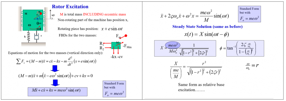
What force is responsible for the vibration of the table (whîch is actually an external component)? The system vibrates and since it is in contact with the table, it will inevitably transmit the vibration to the table, too. Consequently, the force comes from inside the system, the ring itself. By setting the stiffness and the damping coefficient to zero the system will still vibrate since the force comes from inside the ring. When you take e.g. the rotor with the eccentric mass in outer space (in void) in absence of gravitational forces, the rotating unbalance will still vibrate. Excitation is the force being the cause of vibration (it is actually the initial cause). In the example with the rotating unbalance the role of the excitation is being played by the centripetal force (see Rotor Excitation graph above). When the eccentric mass does not rotate then there is no excitation force, resulting in no vibration of the system.
-
I shared the above as a reply to swansont regarding that internal forces are the cause of vibration (we speak always for the experiments and the similarity with a rotating unbalance) where the differential equation cannot justify (I think this is very clear, although you tend to ignore it). Your blender vibrates because it is a rotating unbalance and not a vibrating string with a mass attached. In absence of gravity, it would have the same behavior (vibrating). You still have the focus on Exp #1, which is more complicated I would say. Please revisit the About me section of my Profile and watch the LEGO car (Exp #2) and the rotating ring (Exp #3) videos. Those two experiments have nothing to do with your claims above. Especially, the rotating ring (Exp #3) where the rotation is controlled by manually shifting the excitation frequency (increasing frequency -> clockwise rotation, decreasing frequency -> counterclockwise).
-
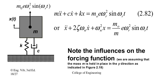
When motion is involved, pictures are useless. It requires videos instead. I am asking you how you explain and not how I see it. However, you still ignore Newton's 3rd law for an isolated system. Do whatever you like, I don't care. Contact forces are supporting and not excitation forces. You are forcing me to refer to the rotating unbalance for once more. Since you are good at maths (and not only you), if you check the second order inhomogeneous differential equation and its particular solution, you will realize as the differential equation as also its solution, may justify only the response of the system. In terms of physics, it fails to justify the cause of the effect of vibration of the isolated system itself (no external excitation forces, no gravity, nothing) since there are only internal forces at play. If you do not agree with the above statement then, you cannot clearly identify all parts of the differential equation. I just found quickly an image from internet showing the differential equation. See below: Could you show me the excitation force on the above differential equation? Isn't just the RHS of the equation or not? Now in order to simplify the above system, set the stiffness (k) and the damping coefficient (c) to zero. What remains? Note: Gravity is not taking into account (see differential equation) therefore the system is isolated. It means the system vibrates in absence of external forces. See my answer above this comment.

-
It is clear that you cannot explain why a device should vibrate in the context of Newton's 3rd law regarding just internal forces. There is an apparent difference between a rotating unbalance and a vibrating spring with a mass attached. Anyway, I am not going to continue the discussion about the eccentric mass, the current thread has a different subject. So, forget about it and just focus on the questions below: a) Why a solid mass like the ring, having no moving parts, should start moving as seen on that video? b) Why the LEGO car starts moving from the moment the ring is on its back? Could anyone push his car while being inside? Definitely, not! c) Why the rotating ring moves with a 100% controllable rotating direction just by applying a frequency shift (increased frequency -> turns clockwise, decreasing frequency -> turns counterclockwise)? The main question is: Since there are no excitation external forces, how the ring moves? Newton's 3rd law forbids motion by means of internal forces.
-
How one could show to someone else a phenomenon that requires some explanation? Just by writing. Who is going to believe it? None. And because of this you would be happy to close the thread by judging the person who opened that thread does not understand physics. Well, maybe I don't understand physics so well, however this doesn't forbid me to think and to raise questions. So, here there is a chance to discuss a subject by having some kind of evidence. Just by throwing the words "vibrations" and "magnetostriction" cannot justify the motion of the core across the table or the LEGO car motion or the controllable rotation. Allow me to share the Link to the experiments in order for anyone to have a decent point of view. In the About me section of my Profile I have the link to the Experiments. swansont, if you close the thread because of this, it will automatically prove the mods act in the name of discrimination and dishonesty. It is your call. Well this is the usual answer most people give, however they cannot justify why the ring should move from the moment there are no external excitation forces at play (horizontal plane). By claiming the vibration is the solution to the puzzle, it cannot justify the motion itself (see Newton's 3rd law in the context of internal forces). Anyway, it is not in my intentions to go back to the arguments regarding the rotating unbalance thread which in a way these experiments are associated to. Whoever I showed those experiments they claimed the same unjustified vibrations (see Newton's 3rd law in the context of internal forces), however none (I don't understand why) of them address the video with the LEGO car. The ring is placed on the back of the LEGO car which is the only component that could be blamed pushing the LEGO car forwards. Consequently, according to Newton's 3rd law the LEGO car should never move, however and unexpectedly it moves.
-
Yes, there is a noise coming from the core. However, if you could have let the videos been watched by the members you would have noticed (Exp #3) there is one where the rotation of the core is controllable by shifting the frequency manually. Consequently, magnetostriction is half the answer. What is the problem to discuss the subject by having additionally some experimental results made by the initiator (me)of this thread? I will place the link to the videos in my signature. I hope you will not close the thread because of this.
-
No there is not. I placed a description and the experimental results (the link with the video). Where is the problem? Without the experiments the discussion is useless. As you already have noticed the exchemist already participates in the discussion and has already raised some questions.
-
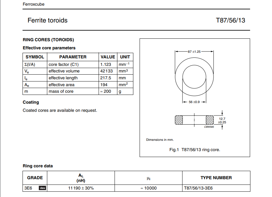
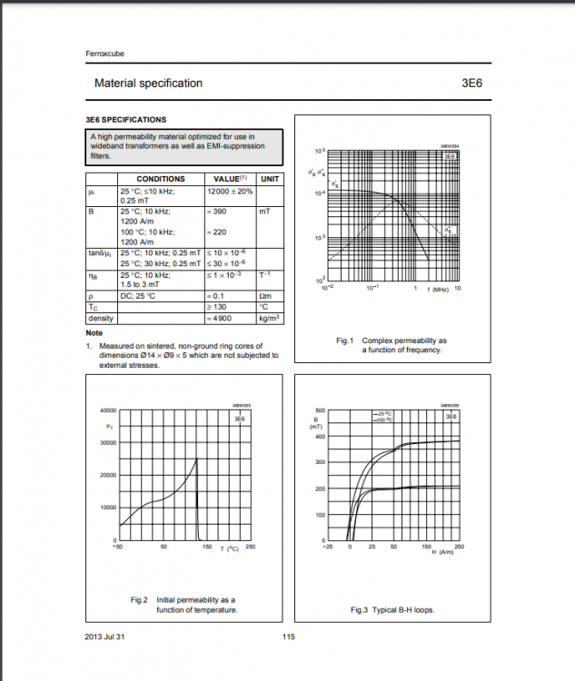
About your questions: -We speak about the MnZn (Manganese Zinc alloy) ferromagnetic core named T87/56/13 3E6 Grade. See technical details below: -The ring core data as also the topology of the ring itself will practically keep all magnetic field lines inside the core. Therefore, the table metal legs and other components will not affect its behavior. -The table is flat. -The ring creates a very loud sound as you may have already noticed by watching the videos. -I never hold it in my hands. -When I first witnessed this phenomenon the ring was placed on the floor away from any metal objects and had a similar behavior. Take into consideration that any change in the current affects the electromagnetic characteristics of the core, namely the magnetic permeability. See B-H Curve below:
-
The physical arrangement of the components is clearly seen in Exp #1 and Exp #3. The same arrangement applies to Exp #2. In other words, we have a coil with a ferromagnetic ring as core that has a mass of 0.2 Kgr being electrically connected in series with the 4.7 Ohm resistor (not moving). After powering the L-R circuit, the only component that unexpectedly moves by itself in the setup is just the coil in all three experiments (Exp #1, Exp #2 and Exp #3).
-
OK, I will present the setup with some technical details to help the members understand what is all about. The setup consists of an L-R circuit in series: -Inductance: L = 1mH -> (Ferromagnetic ring as core) -Resistance: R = 4.7 Ohm (High Power Resistor) -Driving Frequency approx. 5 KHz -Current: approx. 0.6A Exp #1: Self-propelled moving ferromagnetic ring. Here we have a special situation like a self-frequency shift. Generator's frequency is kept unchanged. Exp #2: Self-propelled LEGO car (pushing a LEGO car from inside). AM Modulation using a 200mHz (milliHerz) wave as message signal. Exp #3: Self-propelled rotating ferromagnetic ring. Manual frequency shift through the Generator that leads to controlling the rotation direction of the ring. Experiments: https://www.youtube.com/channel/UCyHiYTj88O2ylGEXcq3am4w I am searching for an answer in the following questions: a) Since there are no external forces pushing the ferromagnetic ring in any direction in all three videos then, how does it move? b) if (a) is correct then, what Newton's 3rd law has to say about it?
-
Understood.
-
Hi everybody! I would like to share three experiments I conducted some 11 years ago as also I may share all the technical details in case there is interest to make some calculations: url deleted per rule 2.7 I am searching for an answer in the following questions: a) Since there are no external forces pushing the ferromagnetic ring in any direction in all three videos then, how does it move? b) if (a) is correct then, what Newton's 3rd law has to say about it?
-
I made an observation and I felt I would like to share it. The thread "Isolated rotating unbalance. Why is there a vibration?" was aired not even for 24 hours. You didn't give me time to respond as also if you go back to that thread you will read several inconsistencies coming from other members. Who cares anyway! I would suggest to the mods of this forum, the following that will benefit everyone: Just for the Speculations Section, please allow members to open a thread in order to discuss their idea (even if it they are wrong) but give them a maximum time of 7 days (1 week) to comply, meaning to develop his/her arguments and answer your questions. If he/she cannot answer your questions or does not conduct a respectful conversation then, the thread should be closed.
-
Sometimes I have a look on this forum and I occasionally note some kind of discriminations. What kind of discriminations? Threads that normally (according to your sensitivities) should have been shutted down, are kept alive (as this one). And when one (as me) attempts to present a different perspective to a problem then, all of a sudden, the moderators want to close the thread as soon as possible by claiming that "I don't understand physics" and "I don't want to learn", by ignoring the inconsistencies of the participants in the discussion.
-
This is correct in terms of momentum conservation, however since the cause of this motion comes from internal forces, the CoM of the system as a whole will not change or better saying the CoM will not accelerate by means of internal forces. Again, not within a cycle but at any instance. Newton does not say the chassis will move (see internal forces and Newton's third law).
-
So here is exactly what I pointed out (after your words): According to Newton's laws of motion, there is no way the frame to move in any direction (up or down) because of an internal rotating mass. We speak about internal forces/momentum that means the frame should never move in any direction. Since the experiment says "it vibrates" then, what Newton has to say about all these?
-
Let's simplify the system by removing the damper and the springs by keeping just the rollers. The constraining forces are not responsible for the vibration along the vertical axis, they just cancel out the horizontal vibration. Let me reformulate the question to show where my point is: The system vibrates upwards and downwards. Question: From the moment the system is isolated (no gravity, nothing), how the system as a whole can move upwards (let's consider just the upwards motion for a moment) and Newton's third law still holds? Normally, it shouldn't vibrate at all since the momentum of the eccentric mass along the vertical axis would be cancelled by the momentum of the rest of the system at any instance. Consequently, no vibration should occur.
-
Hi swansont and studiot! Let me clarify this: The system is isolated (in absence of external forces -> no gravity) and has on board power. Moreover, the eccentric mass has a constant tangential speed. Under these conditions, the system will start vibrate along the vertical axis, right?
-
Hi exchemist! I am not speaking about the obvious things we all know. Regarding the exterior forces, they will not act along the vertical axis of motion of the system. They will not influence system's motion on the vertical axis. Even if the system was not constrained, it would vibrate horizontally and vertically. What I am asking is: How an isolated rotating unbalance may vibrate from the moment Newton's 3rd law holds? In other words, vibration in any direction will automatically violate Newton's 3rd law. Vibration presupposes center of mass redeployment, however this cannot be conducted using internal forces because it would violate Newton's 3rd law. So, how classical mechanics justify the vibration of an isolated rotating unbalance within Newton's laws of motion? Just for the record, I am not training to be a washing machine designer.
-
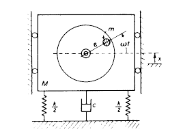
Hi everybody! What is the cause of vibration on the above system (isolated), from the moment there are no external forces?
-


