
Cabwood
Members-
Posts
14 -
Joined
-
Last visited
Content Type
Profiles
Forums
Events
Everything posted by Cabwood
-
Thanks for the picture, it does help. From it I can see that we agree on the direction of forces on the poles of the mobile magnet. Where we obviously don't agree is on the net effect of them. Your diagram shows a net force to the right, which is a lateral force on the magnet, as predicted by Enthalpy early on in the thread (he referred to it as tangential, respecting the circular locus of the magnet). That would cause an acceleration of the magnet to the right, or a clockwise rotation of the arm/disk. But there is also a turning moment on the magnet, due to its orientation wrt the field imposed by the doughnut magnet within its channel/gap. That, as Enthalpy also pointed out, exactly opposes the lateral force, and the magnet/arm/disk won't accelerate anywhere. My reasoning here is that for it to cancel the turning effect of the lateral force, this turning moment on the magnet must have a turning effect on the whole arm/disk, which was my contention from the beginning, and why I introduced the analogy of the wheel/nut/spanner system. (Edit: John, your visual model of the force interaction extending in the first place all the way to the disk centre is very interesting to me. I have focused on local effects, you have seen a global interpretation I missed.) Before Enthalpy's comment, I had not considered the lateral force on the magnet, and consequently this machine seemed to me to behave in a way that does not conserve energy. Now I understand why it doesn't, which was the reason I started this thread. Thanks everyone for your comments.
-
I have no disagreement that forces acting along the radius will not turn the disk. Are we talking about forces from the magnets now, or still about the wheel+nut+spanner?
-
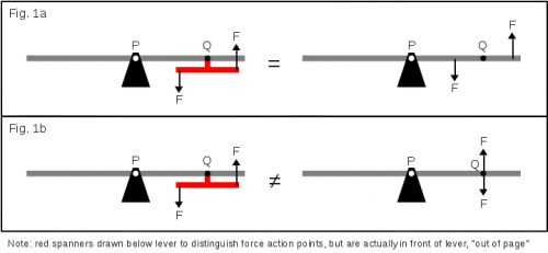
John, I took issue with your statement that you were right, and I reacted inappropriately. So please accept my apology for dragging us into a pointless and upsetting argument. I don't wish to continue that way. I do hope that you can accept my challenges to your judgement regarding this topic, given that I feel strongly (only about the torque issue) that I also have a solid argument, which I shall put here now. Again, I apologise for my unkind words. Your understanding about the where the forces on the spanner are acting on the wheel differs from mine, and I would like to explain my thoughts on this. In the attached figure 1 I have drawn several different configurations of wheel, spanner and forces. I tried to illustrate that due to mechanical rigidity of the wheel & spanner system, a force applied at one end of the spanner will have exactly the same effect as the same force at the same place directly applied to the wheel. My contention is that whether the spanner is merely gripping the nut, or is welded to the wheel at one point, or is a welded to the wheel all along its length, that spanner is part of the wheel, and a force on the spanner has to be treated as if it were a force on the wheel at the same point. Fig. 1a is an attempt to show this. I've used levers instead of wheels, but the principles have not changed. Fig. 1b is an incorrect interpretation of the spanner forces' actions on the wheel. If I thought fig. 1b was correct, I would see no fault with your explanations, but my understanding is that fig. 1a is the correct interpretation. I've drawn the lever diagram again in fig. 2 with moment calculations. As you no doubt know, this system is analysed by finding the net torque at its pivot as the sum of moments due to forces acting along its length (but obviously not at the pivot - I bow to you). And I am convinced that since those spanner forces are not confined to the nut as you suggest, but act on the wheel as though they were directly against it, that this lever model is correct. Consequently I am also convinced that there is a net moment acting about the pivot, which will displace the lever, as calculated on the diagram. I have put together a reasonably rigorous mathematical explanation for this phenomenon. The attached PDF file aims to demonstrate that a torque, modelled as an arbitrarily separated force couple applied to a disk, will cause the disk to rotate. I would draw your attention to the last equation in there - it is independent of force couple separation, orientation of the couple's forces, and position of the couple on the disk. The maths models the general case, meaning that your argument about forces being applied to the nut, and confined within it is not challenged. Lastly, you said that there is symmetry in the design, but I disagree - if the mobile bar magnet was oriented vertically, then the system would be symmetrical. Symmetry is broken because the north and south poles straddle the line of symmetry. Thus forces are not necessarily symmetrical. torque_translation_on_disk.pdf
-
At no point have I claimed that this machine will do anything. I proposed a behaviour and requested comments. I never claimed that this was a free energy machine, or perpetual motion device. It intrigued me, that is all. If anything, my curiosity was aroused because it seemed at first sight to do something that defied physical law, and I wanted to know why, in reality, it wouldn't. You are almost without a doubt right that this will not spin. Now I present this to the forum, as a way to find out why. But for me to find out why, I need more than "I am right" for a lesson. I need to be shown why with at least some degree of mathematical and scientific rigour. On the other hand, this torque issue may not interest you, but I feel sufficiently strongly that this disk will spin if a torque is applied off centre, and that you have an opportunity here to find out why. This is the subject of our debate right now, and you have claimed to be right without any justification. You went from an analogy that I did not understand to a complete dismissal of the problem at hand. There was no analysis, no rigour, no formality, and no method other than analogy to support your claim of being right. For what it's worth I understand your reasoning regarding the central force not contributing to rotation of the disk, and I agree. I apologise that I criticised you on this point.
-
I am sorry that I haven't been able to see how your analogy relates to our problem. A diagram might help. Let me reiterate that I agree it doesn't have a net force moving it up or down, but I insist that you consider more closely that this wheel is not in equilibrium because of the force at P. I think this wheel is able to rotate about its centre to achieve force equilibrium, to a state of lower potential energy, and that, for me, is justification enough to think that it will. One cannot just disregard a force because it seems not to matter. I agree that its contribution is not clear, but that's no reason to disregard it. That's shaky grounds on which to claim you're right - I'll put it down to a knee jerk reaction to frustration that your judgement is being challenged. As for the free energy thing, I told you, it's a thought experiment.
-
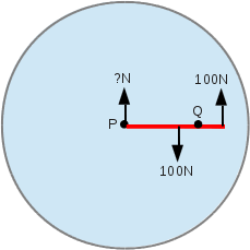
Your argument is correct in the sense that there is equilibrium of linear translational forces, but I dispute the idea that the disk system has rotational equilibrium. Actually, you had me doubting what I said for a while there. All of that said, I am not convinced either that you are wrong. I don't believe this is a perpetual motion machine either. Even if the arm did spin, I questioned whether it would spin indefinitely in my opening post, because I am aware of the law of conservation of energy. This is a thought experiment which may evolve into a physical experiment. I am trying to think of an experiment that would demonstrate either transfer of torque, or no transfer of torque, without having to mechanically apply a torque, or at least apply it mechanically but without any linear force component. I think the plastic disk and wire experiment is a little too subjective. Any ideas? I have just realised we have overlooked a force. In the attached picture, a torque applied at Q would ordinarily cause the disk to want to spin about Q, but can't because of the constraint at P. The disk doesn't spin about Q because there is an upward force from the pivot preventing the centre of the disk from descending. This pivotal force destroys the equilibrium. To seek equilibrium, the disk must rotate anticlockwise about P.
-
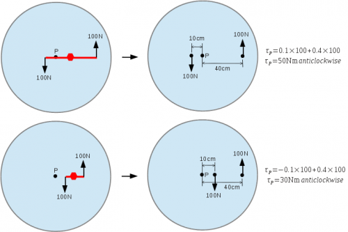
The spanner on the wheel nut is physically bound to the nut and wheel when it is in use (as if it was welded, or part of the wheel itself), and because of this, any force applied to the end of the spanner will not behave differently from a force applied directly to the wheel at the same place. An upwards force (helium balloon) at one end is effectively acting directly on the wheel at the same position, through material stiffness. Similarly a downwards force (rock) is acting directly on the wheel. This will be the case until the nut is loosened. Edit: Think of the spanner (prior to loosening the nut) as a crank, attached to the wheel at an unusual place. I've illustrated this - at the top is a long two-ended spanner, bottom is short. To the left forces are applied to the spanner, but on the right the spanner is removed and the forces are applied directly to the wheel, in the same places. The torque at centre P is calculated for each. Edit: If you calculate the torque on the nut, using the distances in the right-hand diagram, you'll find that they are identical to the torque at P. Thus my understanding is that a torque applied at any point on a wheel will be translated unchanged to wherever the wheel is free to rotate (be it the centre of mass, or a pivot) and act there instead. This does not take into account resultant linear forces which will tend to translate the wheel rather than rotate it - a point raised in one of Enthalpy's posts. The force/torque applied to the disk's magnet is caused by (and in opposition to) the magnets fixed outside the disk, on the frame. So I feel that the individual undoing the bolt is standing on the ground, not on the merry-go-round.
-
Enthalpy, Thanks, your reasoning makes a lot of sense. And you are right, this is fun. The real paradox here is that I actually do get out quite a lot. The story behind all of this, in case you are wondering: A few years ago I played with modelling magnetic systems (in pascal and python), just for fun. The model was based on pairs of monopoles representing dipoles, each pair being close together, separated by, say, 10-8m. The field produced by a dipole is not modelled per se, rather the field potentials at some point wrt to the pair is calculated and summed, as you would calculate electrostatic potentials in the space around a pair of opposite charges. So my model was based on the "electrostatic field" model of magnetic dipoles, rather than the current loop model. Forces on a dipole, due to its presence in the field produced by all other elements of the system, were determined by calculating and summing the force vectors on each of the two component monopoles. That is, each monopole experiences a force due to its presence in the field of every other other monopole, and I simply calculated each force individually and summed them, to find the net force on the monopole. When the forces on both component monopoles of a dipole are known, they can be interpreted as (converted to) a linear force and moment, as experienced by the dipole as a whole. The only omission, that I could see, was consideration of the presence in the system of materials other than free space - because I didn't understand how their permeabilities influence the fields. And I still don't. Perhaps someone could help me with that. At the time, I purchased some small ceramic magnets from a local school supply firm, and performed some experiments with them, to determine their strength and characteristics. It was a lot of fun. I used a magnet suspended on a string (like a pendulum), and another magnet underneath to attract or repel the suspended magnet, measuring the positions, weights and angles to find out the forces involved, and so on. I was able to model these magnets (as described above) to produce very similar (to within 5%) behaviour on the computer. I was elated, because as any student knows, measuring the angle of a string wrt vertical using a cheap protractor is never easy.. My aim was to validate the computer model as well as possible using the tools I had available, so I used it to predict the torque on one magnet in the presence of another, and got results that, to me, vindicated the model. Time went by, and recently I decided to revisit the model, as I just described it, applied to our current problem. Given the absence of consideration of non-free-space materials, and that the monopole-pair representation may not be appropriate, the model I produced of this system is probably deeply flawed. We'll see how it goes. If you guys are interested, I can post the code to the thread (it's a console application written for FreePascal, no fancy graphics), and let your comments guide me. As you say, fun!
-
I reckon that a bicycle stays upright while in motion because if it leans to one side, the front wheel falls to the same side (probably due to gravity, and maybe due to the front wheel's fork being forward of the steering pivot). That causes the wheel to pivot to that side, and the bicycle turns in the direction it is falling, countering the fall. It is inherent negative feedback. A test for this would be to fix the steering in the straight position and see if it falls over when pushed off at speed. Another experiment would be to modify the bike so that the fork points backwards and see how that affects the stability.
-
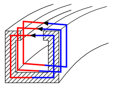
John, this whole idea actually stems from two occasions when I saw similar behaviour while dealing with wheels. While changing a wheel on a car, one has to either use the hand brake to prevent the wheel from spinning when loosening the nuts, or loosen the nuts prior to lifting the wheel off the ground. Otherwise it is next to impossible to prevent the off centre torque (on the nut) from causing the wheel itself to spin. I noticed that even the tiniest torque applied with a screwdriver to an off-centre screw in a small toy's flywheel had the same effect. The wheels have to be physically restrained to prevent torque applied to any off-centre part of the wheel from rotating the whole thing. I just performed a crude little experiment to test this torque idea. I attached one end of a length of thin copper wire with a drop of glue near to the outside of a freely rotating plastic disk (I just cut out a disk from tupperware lid, and poked a nail through it). The wire is solid copper, flexible enough to allow the disk to rotate while holding the wire's loose end immobile, but stiff enough to transmit torsion along its length. As the loose end is twisted (being careful to avoid movement relative to the disk centre), a weak torque arrives at the glue spot, and the disk does actually rotate. My maths points to this effect, and my little experiment points to this effect, but I admit this is not conclusive evidence. Ronald, swansont, Sorry the schematic wasn't clear enough. I've attached a another picture to show the looping field lines.
-
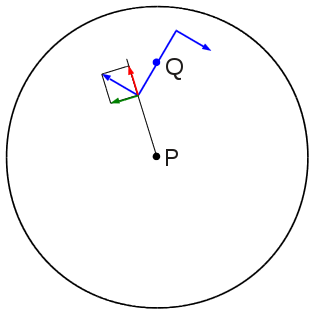
If this system was not using magnets, and instead a torque was applied anywhere along the arm, the arm would rotate about the pivot. If the torque is treated as two individual forces of a couple, it can be shown to act on the arm as a whole. I'm not absolutely certain that my thinking is correct, so I've attached a diagram illustrating my thoughts on this, for comment. In the picture, the couple (blue) acting at Q consists of two forces, each of which can be resolved into forces through the disk centre (red) and perpendicular to that (green). The combined moments due to these perpendicular components of both forces is non-zero, representing a non-zero net moment on the disk about its centre P. In our scenario, the torque on the bar magnet provides the couple of forces. The pivot and doughnut form a fixed frame. The couple consists of forces which push and pull with respect to this frame, and any rotational acceleration of the disk (or rather, arm) occurs with respect to the frame. Also, I spent most of the evening reading up about vector field divergence, in particular the zero divergence of magnetic fields, and I understand now what this means. I still do not see what role that plays in this scenario, so please elaborate.
-
Can you explain to me what divergence means in this context? My understanding is that each dipole of the bar magnet finds itself in a field produced by another source, nearly perpendicular to its own, and will experience torque. How does divergence tell us that the net torque is zero?
-
Is there any strong indication right now that the total mass, and total energy, and total volume, and total anything of the entire universe (all of it) is not zero? It seems to me that every parameter we use to define the cosmos can have its equal and opposite, and that when the whole is viewed from outside, it's quite possible that nothing would be seen because it all adds up to nothing. If true, then the universe doesn't exist at all, except for those who can't see all of it. Which is all of us. If true, then all we see is a small bunch of things which form a part of the total nothing.
-
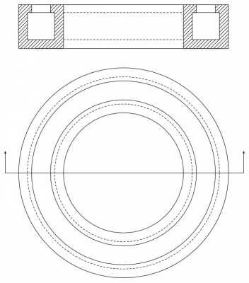
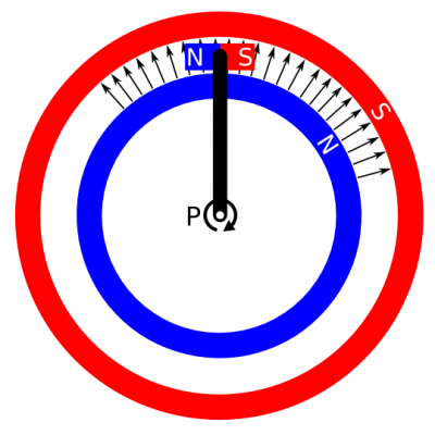
Hey everyone, I have some questions about a mechanism with permanent magnets. The first attachment (magnet1.png) is an engineering drawing of a design of one of the magnets needed for the mechanism. The cross section at top has a gap where a magnetic field is presented to open space, rather like a horseshoe magnet. This shape is extruded around a full circle into a doughnut form, shown in the bottom plan view. The field present in the gap is intended to be radial, centred at he doughnut centre, but only present in the gap - this is illustrated in the second attachment. The second picture (magnet2.png) is a functional diagram of the whole mechanism. The red and blue rings correspond to the doughnut magnets upper section, with the field gap (white) between them. The radial arrows represent the magnetic field produced by the doughnut magnet within its gap. An arm, free to rotate about pivot P (at the doughnut centre), has a regular bar magnet attached at the other end. The bar magnet is positioned in the gap, and oriented such that its internal field is perpendicular to the radial outer field. Here's the point: the bar magnet will experience a torque clockwise, and because it is fixed to the arm, that torque will translate to P. The arm will then rotate, and the bar magnet will accelerate along a path inside the gap. Since as it travels along that path it remains always perpendicular to the doughnut magnet's field, it is always experiencing clockwise torque, and thus continuously accelerating. Ignoring material strength, friction, eddy currents and whatever, there's nothing to stop it accelerating. The questions then are: Will it really keep on accelerating, until friction is dominant, or it breaks? If not, why not? If yes, where is the kinetic energy coming from? The magnetic fields of the permanent magnets? Are those magnets becoming de-magnetised? I'd love to know what you all think. Cheers.

