Dan Bullard
Members
-
Joined
-
Last visited
Everything posted by Dan Bullard
-
I am asking for you "science experts" to answer why this is true. I have a gut feeling, and proof that it's true, as did Mendel with his laws of inheritance but I don't know the math behind why. But one thing you did for me for sure, you once again proved that nobody here understands the first thing about waves and harmonics. That is telling, and probably means there is no reason to hang out here. YouTube video removed by moderator
-
Crossover distortion is zero crossing distortion. The idea that using Class B amplifiers to "reduce/theoretically eliminate intense RF harmonic activity in power control circuitry and not in anyway connected to harmonic distortion in circuits" is bunk. The harmonics are there, just lower in amplitude than you can see and claiming something like this just means that you don't have the resolution to see it. I've used 18 bit, 20 bit and 24 bit digitizers (Credence, LTX, Schlumberger, Applicos, etc) and I have seen harmonics creep in at levels down below the -100dB level. Just because you can't see it doesn't mean it's not happening, and in an RF application, as I mentioned you cannot transmit harmonics. I used to work on 40KW HF transmitters in the outback in Western Australia, and the final stage was a Class C air cooled tube amplifier (triode) that had monster RF inductors and tunable vacuum capacitors which served to eliminate harmonics created in the output tube before it went out to the antenna. And just down the road from me was (at the time) the tallest man-made structure in the Southern hemisphere, the antenna array for a 2MW VLF transmitter used to send nuclear launch codes to submerged US subs in event of a nuclear war. The inductors there were the size of a small car, and you could hold up a 40W florescent light bulb and watch it light without any wires connected to it while the transmitter was operating, it was amazing. Again, the purpose of the inductors was to use along with giant capacitors to form a resonant tank circuit in the 10KHz range. The inductor was built on wooden frames and was tunable! All in an effort to remove harmonics caused by the ten water cooled Class C tubes used as power amps. If you try to transmit harmonics your signal will step on a lot of other applications and I think the FCC has a rule about that. That is what I had to tell my customer in Florida, after getting a nice holiday in the middle of an Oregon snowstorm. It cost me a $100 an hour job but continuing to spend their VC's $1 million on their "new technology" was pointless and I knew it, and now, so do they. NTSC, HDTV, and virtually all forms of modulation from QAM to AM find clever ways to reduce harmonics. QAM is one of the best, but still, those harmonics do exist and the output amplifier has some form of filtering to eliminate them. I doubt that there are any forms of "non-harmonic distortion" as the only way that a non-sinewave can exist is with the presence of harmonics. I suspect that you are trying to minimize my discoveries by claiming that other things in electronics are more interesting. Well, maybe. I've worked on Intel and Motorola uPs, Analog Devices MEMS chips, F16 HUD chips, Trident nuclear missile chips, chips for China's Ministry of Aerospace (I could tell you more but then I would have to kill you), a Maxim HDTV tuner-on-a-chip where I created a production test program that had a test time under 10 seconds, including calibration of the chip's tuner map, Karaoke chips (my newest boom-box uses a chip I was working on in 1999!), the list goes on forever. It was all interesting, and myself and other people knew about the principles of those devices, but when it came to harmonics the best those other people could do was guess. Well, we don't have to guess anymore, I know how harmonics work and I am trying to spread that knowledge far and wide. To quote Dr. Gad Saad from his latest book, "Many professors forget that their professional responsibility is not only to generate new knowledge (as I did) but also to seek to maximally disseminate it." That is what I am doing here. If this site prefers to ignore new discoveries in science, so be it. Kick me off the site like so many others have. I'll quickly follow that with a YouTube video on my channel informing my 4000 subscribers that this site prefers to bury its head in the sand in the face of new discoveries like I did with Stack Overflow.
-
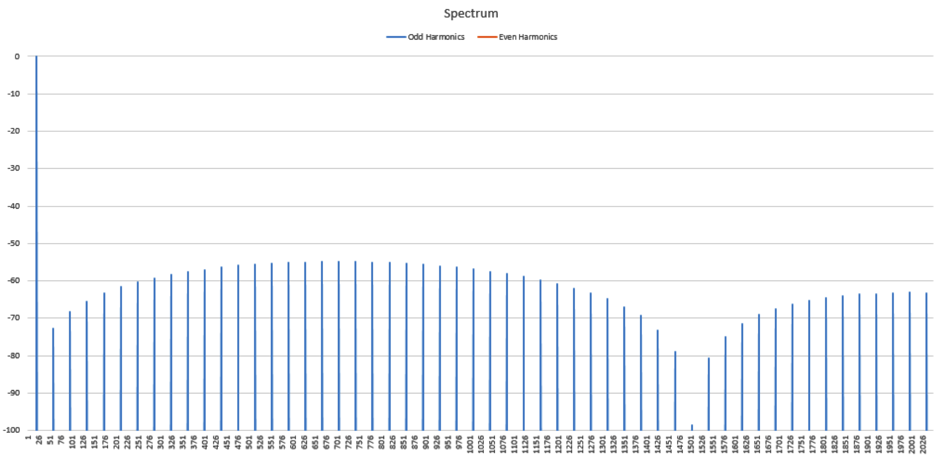
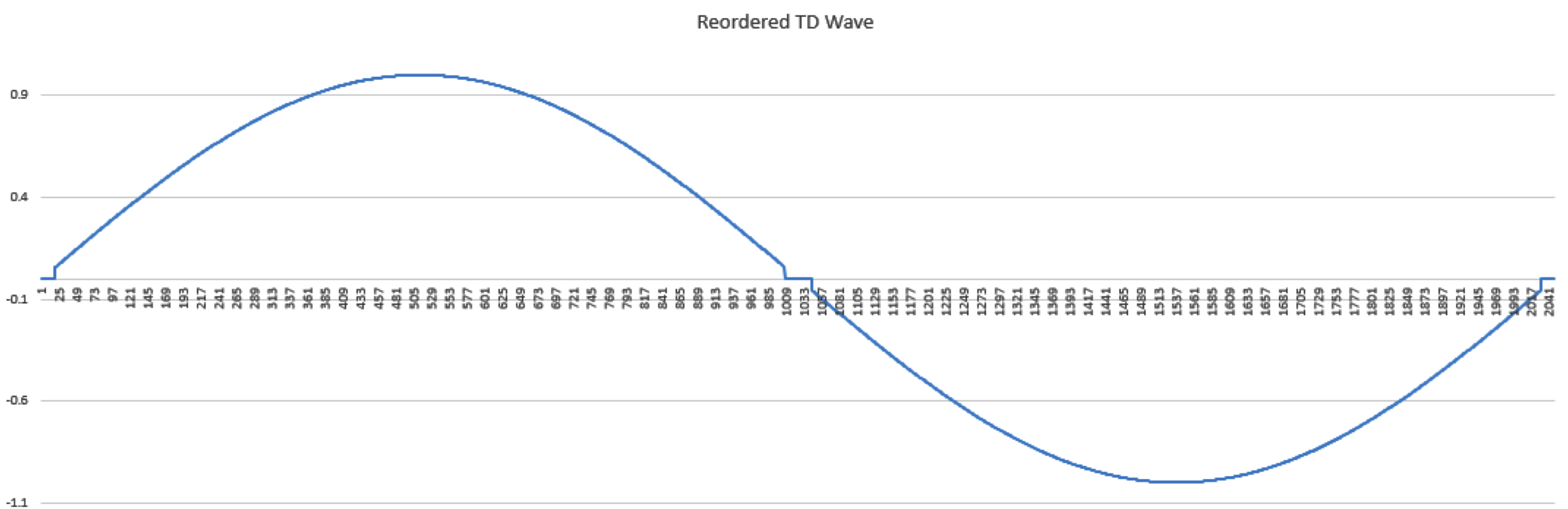
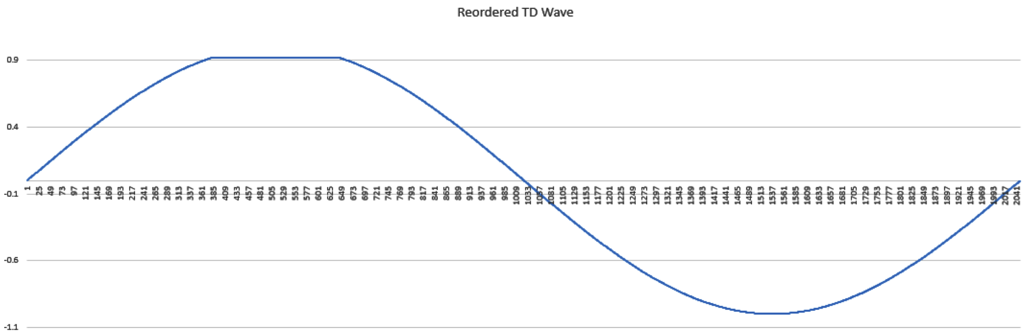
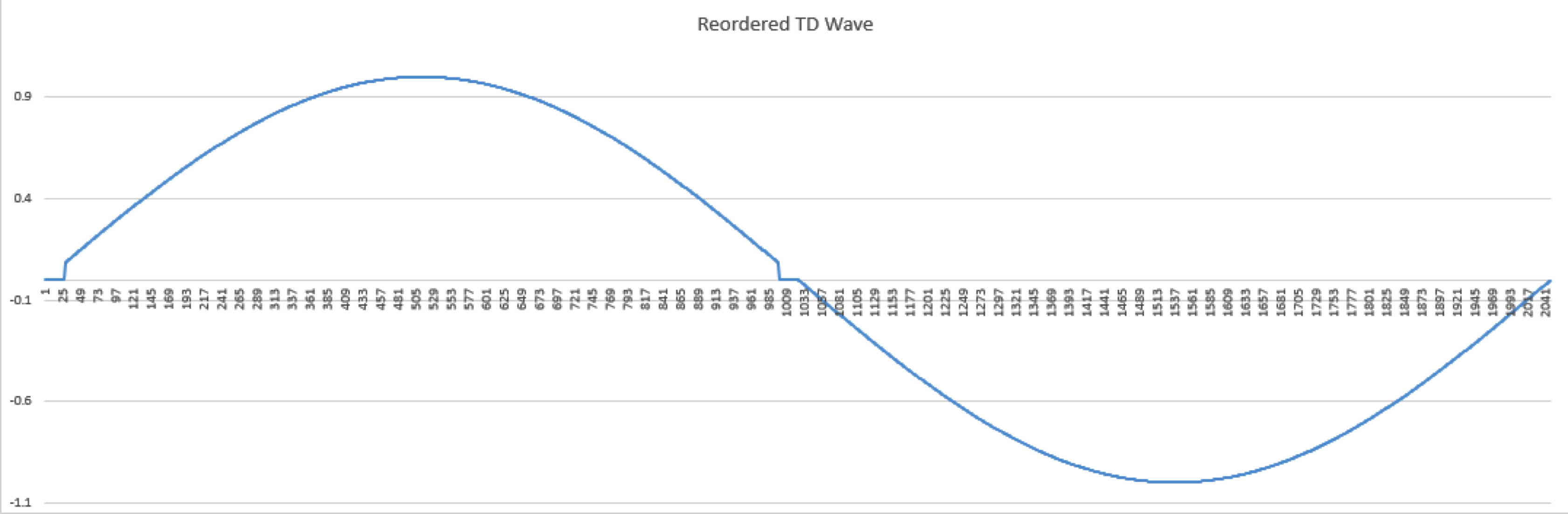
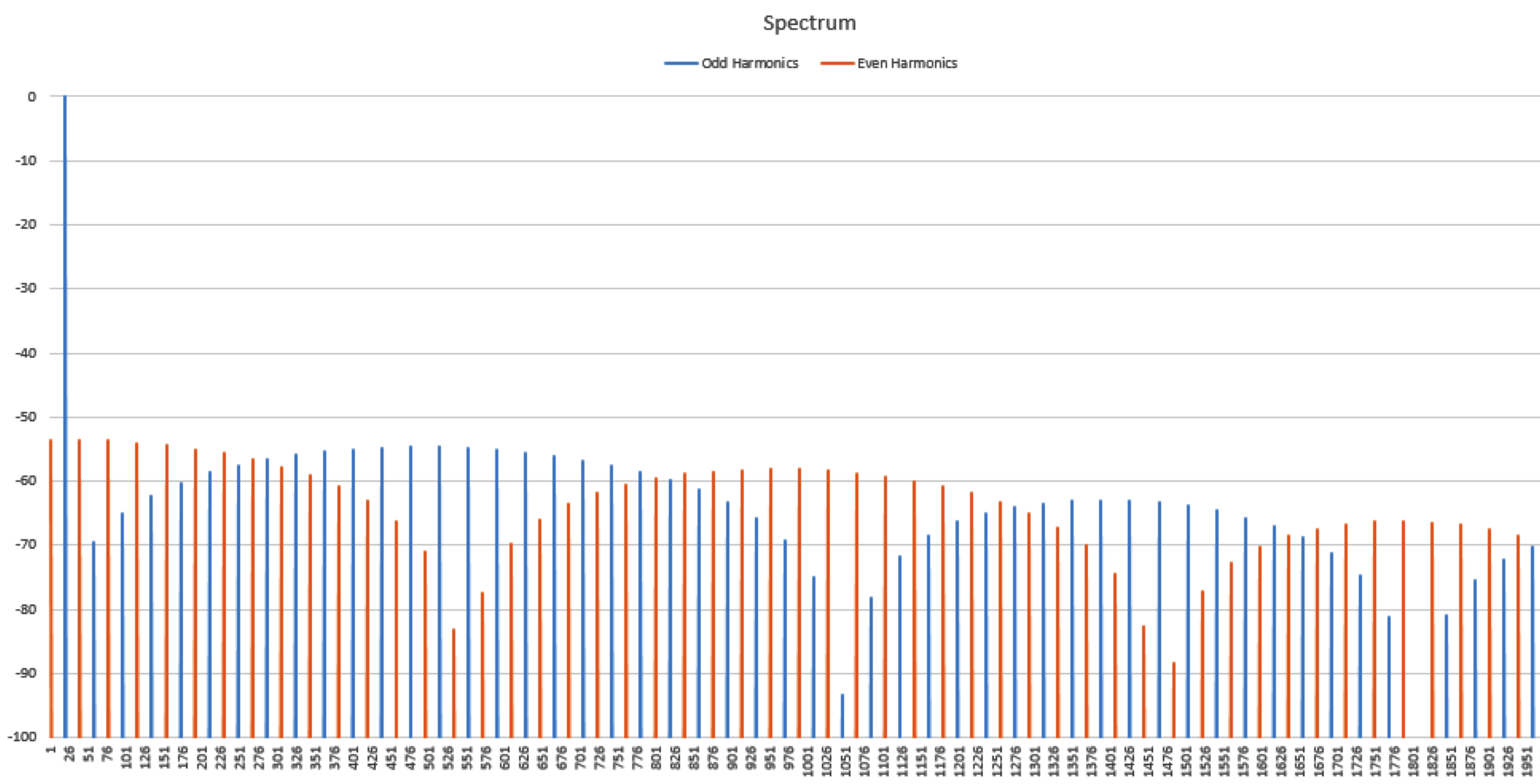
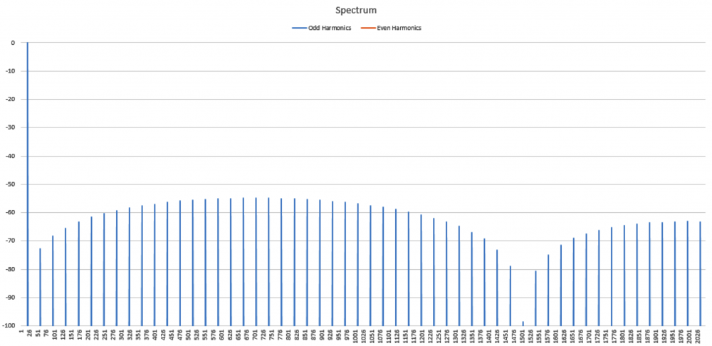
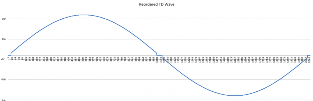
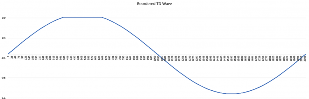
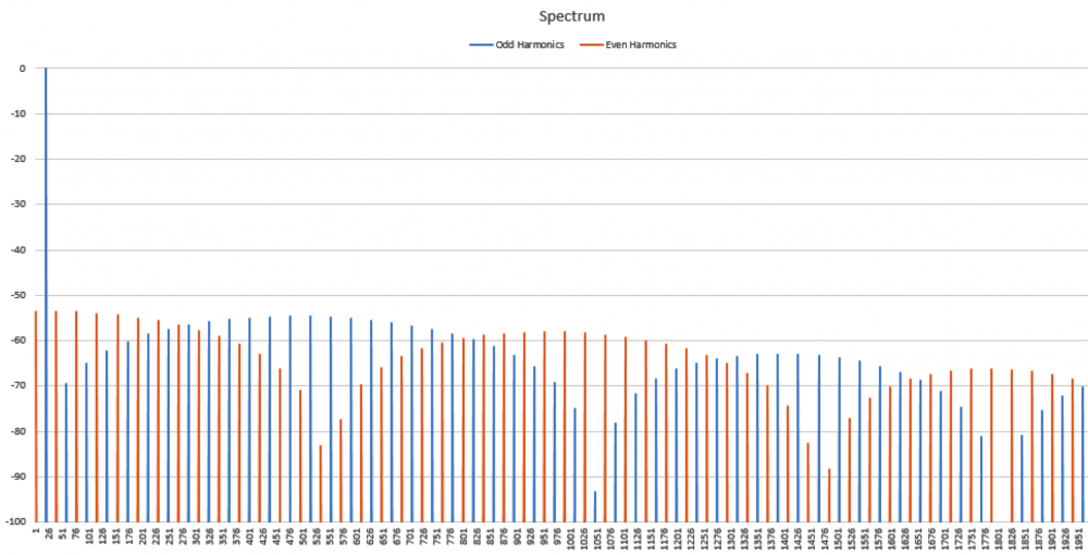
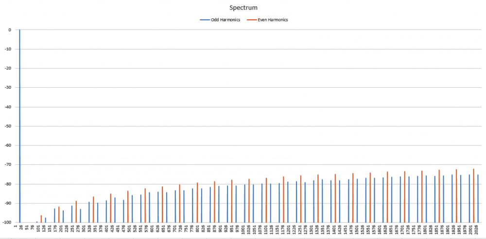
No I am not claiming that339.4sin(100πt)+67.9sin(300πt−3π4)339.4sin(100πt)+67.9sin(300πt−3π4) Distortion in an amplifier (or DAC, ADC, etc) are caused by a failure of the transfer function to accurately pass on the input wave on to the output. If a distortion happens at any angle, it will automatically be replicated later, so for example, if a distortion appears at, say, 66°, it will happen again (90-66) + 90, or 114°, absolutely guaranteed. That will cause all harmonics created to occur with a phase offset relative to 90°. If the distortion happens at, say, 200°, a perfect sine wave will hit it again at (270-200)+270 or 340°. It helps if you understand how electronics work to start with. Every amplifier, DAC or ADC (which I have written code to test millions of) will treat a sine wave as a two way street, what goes up, must come down, and what goes down, must come up. As I say in one of my videos, if a distortion doesn't hit you by the time you get to 270° in a sine wave, it won't hit one, period. If you jump on a trampoline and don't crash into the roof on the way up you will not hit the roof on the way down, absolutely guaranteed. Nothing happens only once in a sine wave, except for two places, 90° and 270°. Anything that happens only once will not cause "measurable harmonics," that is, yes, there will be harmonics, but they will disappear instantly, before your instrumentation gets a chance to see them. It's Daver's Law, somehow a typo snuck in. And you won't find it anywhere other than LinkedIn or my website. Here is a reference: https://www.linkedin.com/pulse/gets-even-better-dan-bullard/ Allow me to address the Zero Crossing issue. Back in the old days there arose a Push-Pull amplifier topology that was called a Class B amplifier. Class B amplifiers worked great, but not as good as they first thought because for a small portion of the transfer function, both transistors would be off as the bases were grounded. So for 1.2V to 1.4V both transistors would be off. Now, this doesn't sound like too much of a problem because the voltage of the sine wave is near zero at that point, so who will miss that small portion of the zero crossing, right? Nobody can even see it, so who cares? Well, not so fast. Assume the transistors are will matched (P and N having similar barrier voltages). This will result in a perfectly symmetrical distortion right at the zero crossing, and because they are symmetrical, there will be no Even harmonics, only Odd harmonics. And the odd harmonics do not start out right away thanks to the other topic that I mentioned that has been tyrannically closed. The phase angle determines the harmonic signature and it's very different at the zero crossing (180°) than it is near the positive or negative peak. It will look like this There is a problem there, because nobody (NOBODY) looks at harmonics for THD above the 5th harmonic, or the 7th, or in rarer cases, the 9th. Remember, these are odd harmonics, so count by two. The fundamental comes first, then the 3rd, then the 5th, then the 9th. The 9th is only at -65dB or so, so nobody cares, right? WRONG!!! Maxim Integrated Products got bit by this one so now they cover the entire audio band (DC-20KHz) when testing their THD values, but most companies could care less (Maxim is better than most). If the distortion is asymmetrical, like in this case where I distort just one side of the transfer function. Now you get a completely different spectrum. Notice how the even harmonics (yes, the red ones) start off very high and then dive down low, but the odd (yes, the blue ones) start off down in the noise floor and rise up to a peak at the point where the even harmonics are now at their first minimum. This is why the phase angle where the distortion occurs is so important, nearer the peaks the odd and even harmonics follow a similar trajectory, but in a zero crossing (distortion can happen anywhere, even now that Class B amplifiers are out of favor) the odd and even harmonics appear out of phase and that can cause some serious problems. Counting some random number of harmonics to get a THD number is a fools errand, because you have no idea where the distortion may have happened, so you can't even begin to guess what the harmonics are going to do. If you can get very unlucky you may get something like this. This will be seen by most users that measure THD the traditional way as a perfect wave, because nothing happens until the 10th harmonic, well after most programs and instruments have stopped looking at harmonics to sum up into a THD number (except at Maxim). But it is a problem because the harmonic signature continues to rise up out of the noise floor, and while some can't hear the difference, some can, and you want all your customers happy, not just a few. Plus, if this is supposed to used in an RF function, you are probably counting on those harmonics to reproduce your wave accurately, and one customer actually tried to get away with something like this for transmitting data. Sure, I got a free trip to Florida and $100 an hour consulting for two days before I convinced then that you can't transmit harmonics on radio when you are confined to a very small bandwidth, the harmonics will never make it out to the antenna.


-
If you can capture it accurately, any distorted sine wave, when taken apart by an FFT will reveal that the phases of the harmonics will always be at 0°, 90°, 180° and 270° relative to the sine wave fundamental, without fail. This is not well known, since most people look only at the magnitude (amplitude) of the spectrum and not the harmonic phases, but if you do, you will "discover" this law. Even more interestingly, if you shift the wave over by 90° to make it a cosine wave, you will find that after doing the FFT, the harmonic phases are at exactly two values, 0° and 180° relative to the fundamental. In this animated GIF I apply 6 different distortions to a cosine wave and prove "Da er's Law" with a scatter plot showing the phases of all harmonics from the fundamental through the sampling frequency, aka Fs. This plot was made in Excel, it is not a hand drawing, this is real data taken from the functions mentioned. Notice that no matter what the distortion is, whether it's peak clipping, asymmetrical or symmetrical, zero crossing clipping, either asymmetrical or symmetrical, a distortion in any portion of the transfer function, the phases of the harmonics in the scatter plot never vary from 0° or 180°. The same thing happens if I do this on a sine wave, but the phases move between four different values as mentioned. If you can't capture the wave as a perfect sine or cosine wave, you are SOL because the phases of the harmonics will be all over the place, seemingly random numbers, although there is a way around this limitation. This is not true if you are talking about noise, this only applies to distortion caused by faults in the device's transfer function. Why is this law true?
-
Magnitude is defined as the unsigned value of any quantity. When an FFT is done, the magnitude (aka Amplitude) is extracted with the formula given, and given the double (actually triple dose) of sign removal (any value squared is positive and the square root of any number is a positive value), there is no way the magnitude could be a negative value.
-
Somebody on this site (I won't name drop) said that he was surprised that the magnitudes of my spectrum were not negative. Do you "scienceforum" people not understand the formula for magnitude = sqrt(amp.re^2+amp.im^2)? Exactly how do you get a negative value out of that?
-
I give away everything else, but this one thing is only understandable if you understand 1) Total Distortion Energy (TDE) and 2) the formula for predicting harmonics from the duty cycle of a square wave and triangle wave. I don't have the time to cover them all online and I have to leave some reason for people to read the books. I give you all 5 laws of the Bullard Laws of Harmonics, the formula for the Bullard Harmonic Solution isn't going to make any difference to this discussion, and if you are so smart, derive with it yourself. The video proves that it is valid, and that is all you need to know. When everyone else is arguing over how many angels can dance on the head of a pin, what's the point in giving you a formula that you won't understand?
-
More detail, OK, I can't give you the formula (intellectual property) but I can show how the Bullard Harmonic Solution accurately predicts the harmonic signature in this video.
-
Which peak is clipped cannot be seen in the magnitude portion of the spectrum, it doesn't matter which peak is clipped, the harmonic signature is identical. Only the phases of the EVEN harmonics are different. In this animation, based on real data I extracted from the FFT that I made in Excel shows how the harmonic phases determine which peak is clipped. Notice that when both peaks are clipped, the even harmonics (in RED) don't move at all, but when I clip only the positive peak I get even harmonics (again, in RED) to help the ODD harmonics (in BLUE) to make the same size distortion. So why isn't the distortion bigger? Because both the ODD and EVEN harmonics work together to make the distortion, but the EVEN harmonics now oppose the ODD harmonics trying to replicate the distortion on the negative peak.
-
I've been kicked off of most bulletin board sites trying to make this point, but I discovered some interesting things about Harmonics that nobody else seems to know. In this animated GIF I show how the harmonic signature varies as the result of the phase angle where the distortion occurs in a sine wave. Here I show the spectra of several sine waves that were distorted by clipping (at the positive peak) and I record the phase angle where the clipping first started. It's a linear relationship, and I have worked out the formula for this too. This is not caused by the FFT, as I have proven this behavior on analog instruments as well. This is real. Who here wants to kick me off of this site for saying unspeakable things?