DDRDan
Members
-
Joined
-
Last visited
-
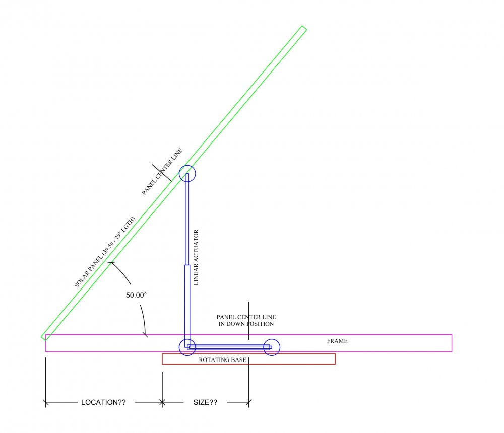
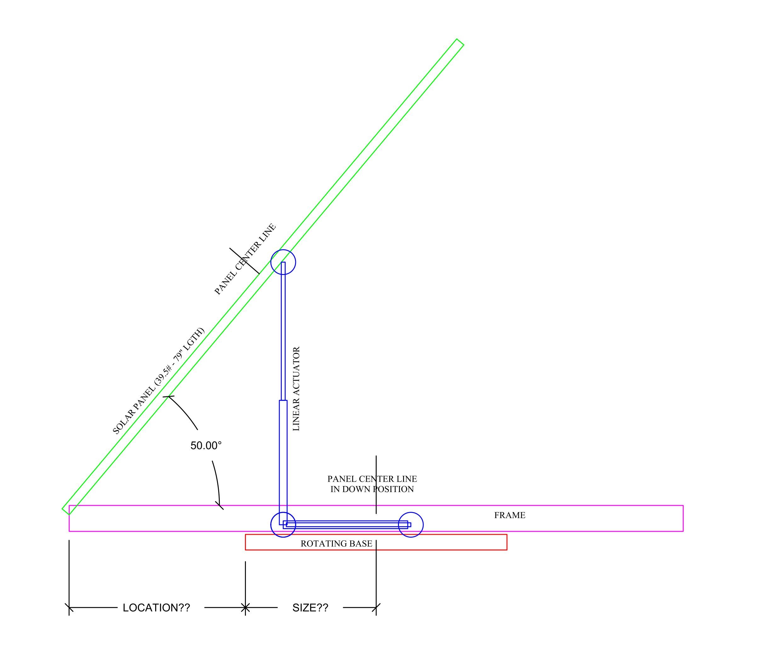
Because of the actuator length required, to get the elevation required, the lift point is 5.5" off center on the panel. And the base of the actuator is always off center in the opposite direction by 6". Giving an 11.5" spread. "does it slide" You just gave me a great idea! Have the panel base pivot point slide/retract along the frame towards the center of the rotating base as the actuator raises it. Bringing the pivot point towards the center line as it goes up! Pretty much maintaining a constant Cog triangle if I design it correctly. And I can use a pair of 100# rated drawer slides to get the movement. Extended when down - retracted when up. I'll need to restrict the drawer slides with an opposing spring to prevent 3 point collapse. Back to the drawing board! Thanks
-
Thanks for the response! The panel is 39"W x 79"L x 1"Thick. It's vertical movement will pivot at the corners on one end of the panel along it's 39" dimension. The actuator is for (X axis) rotation to bring the face of the panel to an adjustable angle that is perpendicular to the suns rays. The rotating base (Y axis) will bring the panel to the compass direction of the sun. Think of a telescope lens in an observatory aligning with a star. And because this is an RV roof I have a height restriction and can not create a 31" tall gimbal A frame to support the panel at its center point for x axis rotation. It must pivot from one end so it will fold flat for transportation. The load at that pivot point being offset and changing from my base connection is my problem. Question: From your post mentioning a counterweight - I'm confused. Won't the entire mass of the panel become a variable as it is sloped and change the Cog? Won't the Cog change with angle and follow the line of the panel towards its pivot point? I have a limited base size. I feel the frame will wobble eccentrically from shifting load changes when the panel elevation changes and destroy the bearing device. I haven't been able to find a rotating bearing device for the Y axis that is over 24" dia. This limits my footprint size to a 30" dia. (See this ref) https://www.amazon.com/dp/B07KDR49KW/?coliid=I2TW5SH4G2XWGH&colid=10YTGQOLYU0DM&ref_=lv_ov_lig_dp_it&th=1 So, I'm thinking, getting the system located as close to a changing center of gravity will help, somewhat? Or, do something I'd rather not do, add a third Z axis actuator and slide the frame back or forth centering the base along the changing Cog when adding slope. My other choice was adding ball wheels at the corners of the frame that would ride on the roof for stabilization. But that means adding reinforcement to the rubber roof in the wheel path. Thanks again.
-
I'm fabricating a 12vdc solar mount system for my RV that will rotate and change sun angle. Getting to old to climb on that roof to raise the panel. I have a mechanical engineering background but I need a little help finding the formulas and any hints or links you may. I don't have experience in motion design. I'm sure this has to have been done before and I thought, "Why reinvent the wheel?" Not asking to have it done for me. Providing all the details would be more difficult than calculating it myself. Areas I need help: Finding the center of gravity at the max 50 degree angle and at increments going down to 0 degrees. Ideas or suggestions for: Best theoretical size for a base. Best theoretical location (in reference to panel center-line) for the base. And best theoretical mounting location suggestions. Thanks in advance for any help Dan PS: not noted on drawing panel is 39" wide