


czarodziej_snow
-
Posts
10 -
Joined
-
Last visited
Content Type
Profiles
Forums
Events
Posts posted by czarodziej_snow
-
-
22 hours ago, Bender said:
Never mind, I misread. It is getting late.
So in summary : what's new? The simulation looks nice, but you aren't exactly the first to make one of this well known and well documented effect.
My simulations show a lot more of details which you will not see elsewhere, and angular acceleration or moment of force is a completely new approach to this issue
0 -
49 minutes ago, Bender said:
I didn't go through all the details, but you made an error in this step. On the left hand side, you assume omega is constant, which makes the right hand side 0.
which exactly step?
During the mechanics of rotation of the rigid body angular velocity is constant only in three special cases only when it rotates exactly around one of the main axes of the moment of inertia in other cases, the vector is not stable in the body frame and inertial frame. It shows my animation
another simulation shows the same
There was an error in my Euler patterns, I will try to fix it quickly
How to edit a note?
correction of Euler's equations
Ix(dωx/dt)= (Iy - Iz)ωzωy
Iy(dωy/dt)= (Iz - Ix)ωzωx
Iz(dωz/dt)= (Ix - Iy)ωxωy
0 -
I am interested in the mechanics of rigid body rotation. I entered the subject very deeply, and from my calculations and conclusions it follows that, not everything is exactly that haw it is written in books and few details have hidden in present science . Of course, these are my conclusions and should be verified but no one did not get interested, and physicists are afraid of the subject, like the devil of holy water.
I thought I might find people here with whom I could discuss the issue, but because the questions for I am looking answers can not be found in books, they only hear excuses. Unfortunately, the local community is just waiting for easy questions which answers can be found in books, and he has not been interested in searching for answers that have not yet been found.
To better introduce you to the topic I prepared simulations showing rigid body rotation based on Poisnot solutions using the ellipsoid concept. Solutions in the sources which I have, it was very chaotically written but I finally managed to understand and sort it.
What is matter?
During the rotation of the rigid body, the moment of inertia is the most important thing. Each rigid body has three constant moments of inertia which is permanently attached to the solid frame. It means that in the body configuration, the moment of inertia is constant over time. Poinsot presented it in the form of an ellipsoid of inertia in the body configuration. It is interesting that, if we have different main moments of inertia and the body rotates near the middle moment of inertia, comes to the Dzibibekov effect that is, for spontaneous change of the instantaneous axis of rotation. There is a spontaneous change of the angular velocity and changes in the moment of inertia. These changes are not chaotic and predicted that angular velocity vector moves at the intersection of ellipsoid of angular momentum and energy ellipsoid. That's was written but how to understand ellipsoid of angular momentum when the angular momentum is constant over time?
My solution is quite simple. Because angular momentum is constans he creates a sphere.
L2=Ix2ωx2+ Iy2ωy2+ Iz2ωz2 =Lx2+ Ly2+L2z
L=constans
Energy is also constant over time and if we used it directly, we would get another sphere. Energy is
E=Iω2/2
Angular momentum is
L=Iω
E=L2/2I
L2=2EIx+2EIy+2EIz
Angular momentum is constans in the inertial frame, but is not must be constans relative to the rigid body. This sphere of angular momentum and ellipsoid 2EI are solid relative to the rigid body, so they will rotate with this body in the inertial system. Angular momentum vector is constans in inertial and always it's at the intersection this sphere and the ellipsoid. In rigid body frame this sphere and the ellipsoid they do not move but the angular momentum vector moves along their intersection.
Analogously, we can determine the ellipsoid for the angular velocity vector
Ω2=2E/Ix+2E/Iy+2E/Iz
Ω2=(L/Ix)2+(L/Iy)2+(L/Iz)2
Angular velocity vector moves along their intersection these ellipsoids. Everything is showing my animation.The rotation of the rigid body describes Euler's equations
Ix(ωx/dt)= (Iy - Iz)ωzωy
Iy(ωy/dt)= (Iz - Ix)ωzωx
Iz(ωz/dt)= (Ix - Iy)ωxωy
I do not know why no one did not see of the relations that resulted from them, ω/dt is definitely the vector of angular accelerations ɛ and Iɛ it is a moment of force. Important, I is the tensor of the moment of inertia, which very complicates calculations but I have pass through it and now I can use it effectively in simulations.
There is a superstition that isolated bodies can not have inner moments of forces and internal angular accelerations, but Euler's equations deny it. I have heard a lot of opinion that such a moment of froce would have to be incompatible with the laws of physics, but I examined this moment of force and dont found nothing in it that would contradict any of the laws of Physics. These opinions is result from ignorance, lack of scientific approach and intuitive estimates, dont have nothing to do with the truth.
I have proof though it is not yet complete.
Conservation of linear angular momentum
dL/dt=0 (1)
Angular momentum is
L= Iω (2)
use (1) and (2)
d(Iω)/dt= ω(dI/dt) + Iɛ =0 (3)
moment of force is
M= Iɛ (4)
We know that during the rigit body rotation mechanics, the moment of inertia changes over time I showed it in my simulation above . Changing (3)
dI/dt=-M/ω (5)
we have a pattern for the inner moment of strength
M=-ω(dI/dt) (6)
we count the derivative with dI/dt
M=-ω(dmr^2)/dt (7)
M=-ωm(2r(dr/dt))=-2ωmrv (8)
momentum is
p=mv (9)
We have now
M=-2ωrp (10)
Second law of Kepler
dA/dt=r(dr/dt)/2= (r x v) /2 = (r x p)/2m (11)
S=dA/dt= constans (12)
Angular momentum is
L = r x p = r x mv (13)
Use (11) and (12)
r x v = 2S (14)
Angular momentum is
L=m(r x v)=m2S=2mvr(sina) (15)
Use (15) to (8)
M=-ωL (16)
M=-ω x L (17)
Using the equation (17) I can effectively simulate the mechanics of rotation. At the end I sending the code in Vpython. How does this moment of force look shows my simulation.
https://www.youtube.com/edit?o=U&video_id=8OnWhW1-15s
It is only a fragment of my conclusions, there are still some details that still elude me but I'm on the best way to find them. If anyone would like to help or cooperate, I am open to any suggestions. You will find more simulations and details in simulations on my Youtube profile.
0 -
18 minutes ago, studiot said:
Perhaps I should have said that omega 1, omega2 and omega 3 are the angular velocities about the 3 Euler axes.
A, B and C are the positive constant moments of inertia about these axes.
Without perturbation the system is stable.
If we introduce even the slightest perturbation to omega 2 the instability you are modelling results.
If we introduce that perturbation to omega 1 or 3 then something different happens.
I was asking if your animation can show what happens then?
What equations are you solving to generate the vectors?
Euler's equations.
Ix(dωx /dt) + (Iz - Iy)ωzωy = 0
Iy(dωy /dt)+ (Ix - Iz)ωzωx = 0
Iz(dωz /dt)+ (Iy - Ix)ωxωy = 0
Omega must have minimum two no zero elements. If that hapen equations show you dω.
Haw this vectors work in nointeria frame show difrent my animation.
0 -
21 hours ago, studiot said:
In a perfect world rotation about any of the three Euler axes is stable, an governed by three non linear coupled differential equations.
(B−C)ω2ω3
Bdω2dt=(C−A)ω3ω1
Cdω3dt=(A−B)ω1ω2
Where constants A < B < CBecause of the couping the slightest perturbation of ω2 will lead to regenerative instability of rotation about the intermediate axis as your vids show.
The equation set can be linearised and the linearised equations set still exhibits this instability.
My animation works on Euler's equations. In non-inertial frame I finded angular velocity vector and I rotate this frame in interial frame. In this way, I finded the coordinates of the temporary axis of rotation. And I repeat this step a lot time. One step is a very small error but Thousands of steps cause an error to occur. I know how to check those moments force, but I must find time. I'm a very busy person.
21 hours ago, studiot said:Would you like to explain how your animations improve on this?
Also the above calculations show what happens if you introduce the perturbation into either ω1 or ω3
Can you animations show this?
What improve? This animation shows simple properties this vectors. a=(v1-v0)/dt and F=am. That's all.
Sorry but I do not understand the rest.
0 -
Hi I would like to present my new simulation rotated rigid ball.
Brief introduction to the Dzanibek Effect
When I learned to simulate the effect and study the secrets of vector relationships with no problem to finde speed vectors for points.
Next step is finde acceleration. It is a=(v1-v0)/dt. To spread this vector I set the angle n of inclination of both vectors and line acceleration it is al=cosn*a. Centrifugal acceleration it is ad=a-al.
Now it is easy to determine the force acting on the point. It is F=am. Now I set the angle m between force vector and main axis. Central force is Fc=cosm*F. Remaining component is forces creating a moment of force.
Yellow- Velocity
Red, lighbrown - acceleration and forces
Green - line acceleration
Light blue - centrifugal acceleration
Pink - Central force
Orange – forces give moment of force.
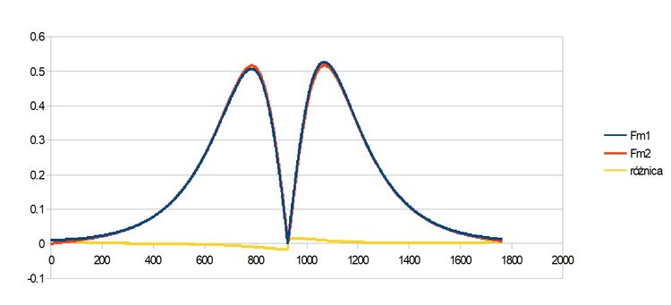
My simulation is not perfect and gives errors of the order of 0.01.
Sum of moments of forces give result max 0.01 but most likely this is a method error.
https://m.salon24.pl/9236008c61194a8bfd80bc37832b8ae7,750,0,0,0.jpg0 -
The mechanics of rigid bodies describe the Euler equations.
Ix(dωx /dt) + (Iz - Iy)ωzωy = 0
Iy(dωy /dt)+ (Ix - Iz)ωzωx = 0
Iz(dωz /dt)+ (Iy - Ix)ωxωy = 0
Important is the difference in moments of inertia on the main axes and angular velocity vector components .
After easy transformations we have
Ixɛx = (Iy - Iz)ωzωy
Iyɛy = (Iz - Ix)ωzωx
Izɛz = (Ix - Iy)ωxωy
Iωω = Iɛ = M - momentum forces
Its easily visualize these vectors
The problem is that Euler's equations work only in non-inertial systems.
0 -
Thanks for the link, I'm trying to understand this deeper
" Is there a question here?"
There are many answers in this note but there are still many questions. The main question, how do the centripetal forces work in this effect?
0 -
Hi
Sorry for my language but I dont speak english very well and probably I have trouble understanding comments.
Over a year ago Professor Jadczyk was interested me Dzanibekov's effect.
https://www.youtube.com/watch?v=BGRWg4aV2mw
Currently I can calculate and simulate a lot. I will use the equations because they are a universal language and they are understandable to all science on over the world.
Vector product.
a x b = c
Perpendicular axis
i ┴ j ┴ k
Proportions of vectors
ck=ai*bj
ai=ck/bj
bj=ck/aiThe inverse of the vector.
a(ax,ay,az)=√(ax2+ay2+az2)
1/a=a/a2=(ax/a2, ay/a2, az/a2)Example
d (1,1,1) 1/d (1/3, 1/3, 1/3)
e (1,1,0) 1/e (1/2, 1/2, 0)
f (1,0,0) 1/f (1,0,0)Easy vector product equations.
c = a x b
a = 1/b x c
b = c x 1/aVector product equations for velocity, angular velocity and position. These equations are correct only for a free point.
v = ω x r = 1/s * m
ω = 1/r x v = 1/m * m/s
r = v x 1/ω = m/s * sIn rigid body rotation usually Angular velocity is not stable.
How to calculate temporary angular velocity for rigid body rotation?
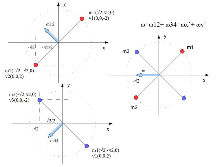
Rigid body elements
m1x`(√2, √2, 0); v1(0,0,-2)
m2x`(-√2, -√2, 0); v2(0,0,2)
m3y`(-√2, √2, 0); v3(0,0,-2)
m4y`(√2, -√2, 0); v4(0,0,2)m1,m2 is x` main axis. m3,m4 is y` main axis. The center of mas is the center of the coordinate system.
We calculate angular velocity for main axis
ωx`=(-√2/2, √2/2, 0)
ωy`=(-√2/2, -√2/2, 0)These are components temporary angular velocity for rigid body rotation
Ω = ωx` + ωy` =(√2, 0, 0)
https://m.salon24.pl/051c2bf7373b20e081ac0f25ababa170,750,0,0,0.jpg
Property vector product:
a x b = c ---> c=absinα
If
Ω (x,0,0) and r (x,y,0)
this give
ry┴Ω i rx║Ω
v = Ω x ryAngular momentum for the free point
L = r x p
Angular momentum for rigid body show that equations using tensor moment of inertia.
Lx= ωxΣmn(rn2-xn2) + ωyΣmnxnyn + ωzΣmnxnzn
Ly= ωxΣmnynxn + ωyΣmn(rn2-yn2) + ωzΣmnynzn
Lz= ωxΣmnznxn + ωyΣmnznyn + ωzΣmn(rn2-zn2)r is the position point to the center of mass.
Easier equations using moment of inertia for main axis
Ix=mxr2 + m-xr2; Iy=myr2=m-yr2
Lx = (r1 x p1)x + (r2 x p2)-x
Ly = (r3 x p3)y + (r4 x p4)-y
Lz = (r5 x p5)z + (r6 x p6)-z
L = Lx + Ly + LzCentripetal acceleration ad for point.
ad=rω2 --> rω=v
ad=v2/r --> v/r=ω
ad=ωvad║-r
Vector product equations for centripetal acceleration
ad = ω x v
ω = 1/v x ad
v =ad x 1/ωEquations temporary angular velocity for rigid body rotation
Ω=ωx`+ωy`+ωz`=(1/v x ad)x` + (1/v x ad)y` + (1/v x ad)z`
Centripetal forces for point in rigid body rotation, three possibilities.
First version
F=am
ω = 1/v x ad
ω = 1/mv x mad
ω = 1/p x Fd
Fd = ω x p
p = Fd x 1/ωSecond version
Ω = (x, 0, 0)
r = rx +ry = r┴ + r║
Fd=mω2 ryThird version
Ω = (x, 0, 0)
r = rx +ry = r┴ + r║
Fd=mω2 r
Fd=m(1/ry x v)2 rAnother animation shows the angular acceleration vector for the effect
Another animation shows the vectors in no inertial frame
code for the first simulation Vpython.
from visual import *
mx=0.5 #masy x`,y`
my=1.
x1=1 #pozycja m1,m2 na osi x`
y1=0
z1=0
x2=0 #pozycja m3,m4 na osi y`
y2=1
z2=0
r=vector(x1,y1,z1) #promien
R=mag(r)
#print R
W=vector(0.9,0,0) #omega
v1=W.x*y1 #predkosci
v2=W.x*-y1
v3=W.x*y2
v4=W.x*-y2
p1=mx*v1 #ped
p2=mx*v2
p3=my*v3
p4=my*v4
ax=(v1*v1) #przyspieszenia a=(v^2)/r; r=1
ay=(v3*v3)
#print "v",v1,v2,v3,v4
TIxx=(2*mx*((y1*y1)+(z1*z1)))+(2*my*((y2*y2)+(z2*z2))) #mx1 i mx2 --> 2*mx
TIyy=(2*mx*((x1*x1)+(z1*z1)))+(2*my*((x2*x2)+(z2*z2))) #elementy tensora
TIzz=(2*mx*((x1*x1)+(y1*y1)))+(2*my*((x2*x2)+(y2*y2)))
TIxy=(2*mx*x1*y1)+(2*my*x2*y2)
TIxz=(2*mx*x1*z1)+(2*my*x2*z2)
TIyx=(2*mx*y1*x1)+(2*my*y2*x2)
TIyz=(2*mx*y1*z1)+(2*my*y2*z2)
TIzx=(2*mx*z1*x1)+(2*my*z2*x2)
TIzy=(2*mx*z1*y1)+(2*my*z2*y2)
Fdx=mx*W.x*W.x*y1 #sily dosrodkowe na osiach glownych z Fd=mW^2ry
Fdy=my*W.x*W.x*y2
#print "F", Fd1,Fd2
Fdax=mx*ax #sily dosrodkowe na osiach glownych z F=ma
Fday=my*ay
#L=vector((W.x*TIxx-W.y*TIxy-W.z*TIxz),(-W.x*TIyx+W.y*TIyy-W.z*TIyz),(-W.x*TIzx-W.y*TIzy+W.z*TIzz))
#print "W",W
omega=arrow(axis=vector(W.x,W.y,0), color= color.blue, shaftwidth=0.05) #omega startowa
#kret=arrow(axis=vector(0,0,0), color= color.red, shaftwidth=0.04)
kret2=arrow(axis=vector(0,0,0),color=vector(1,0.4,0.4), shaftwidth=0.04)
#kret2x=arrow(axis=vector(0,0,0),color=vector(1,1,0.3), shaftwidth=0.04)
#kret2y=arrow(axis=vector(0,0,0),color=vector(1,1,0.3), shaftwidth=0.04)
dv1=arrow(axis=vector(0,0,0), color=vector(0.3,0.6,0), shaftwidth=0.05) #przyspieszenie punktow
dv2=arrow(axis=vector(0,0,0), color=vector(0.3,0.6,0), shaftwidth=0.05)
dv3=arrow(axis=vector(0,0,0), color=vector(0.3,0.6,0), shaftwidth=0.05)
dv4=arrow(axis=vector(0,0,0), color=vector(0.3,0.6,0), shaftwidth=0.05)
dvg=arrow(pos=vector(0,1,0),axis=vector(0,0,0), color=vector(0.6,0.6,0), shaftwidth=0.05)
dvd=arrow(pos=vector(0,-1,0),axis=vector(0,0,0), color=vector(0.6,0.6,0), shaftwidth=0.05)
#omegax=arrow(axis=vector(0,0,0), color= vector(0,0,0.01), shaftwidth=0.02)
#omegay=arrow(axis=vector(1,0,0), color= vector(0,0,0.01), shaftwidth=0.02)
masa1x=sphere(pos=vector(x1,y1,0),radius=0.05) #bryla sztywna
masa2x=sphere(pos=vector(-x1,-y1,0),radius=0.05)
masa1y=sphere(pos=vector(x2,y2,0),radius=0.05)
masa2y=sphere(pos=vector(-x2,-y2,0),radius=0.05)
promien1=arrow(pos=masa2x.pos, axis=masa1x.pos-masa2x.pos, color= color.yellow, shaftwidth=0.005)
promien2=arrow(pos=masa2y.pos, axis=masa1y.pos-masa2y.pos, color= color.yellow, shaftwidth=0.005)
vm1x=arrow(pos=masa1x.pos, axis=vector(0,0,v1), shaftwidth=0.01) #wektory predkosci punktow
vm2x=arrow(pos=masa2x.pos, axis=vector(0,0,v2), color=color.green, shaftwidth=0.01)
vm1y=arrow(pos=masa1y.pos, axis=vector(0,0,v3), color=color.green, shaftwidth=0.01)
vm2y=arrow(pos=masa2y.pos, axis=vector(0,0,v4), color=color.green, shaftwidth=0.01)
#orbita1=ring(pos=vector(x1,0,0), axis=vector(1,0,0), radius=y1, thickness=0.01) #orbita
os=arrow(pos=vector(-2,0,0), axis=vector(4,0,0),color=vector(0.3,0.3,0.3),shaftwidth=0.005) #os obrotu
sila1=arrow(pos=masa1x.pos,axis=-vector(x1,y1,0)*Fdx, color= vector(1,1,0), shaftwidth=0.05) #wektory sil dosrodkowych punktow
sila2=arrow(pos=masa1x.pos,axis=-vector(-x1,-y1,0)*Fdx, color= vector(1,1,0), shaftwidth=0.05)
sila3=arrow(pos=masa1y.pos,axis=-vector(x2,y2,0)*Fdy, color= vector(1,1,0), shaftwidth=0.05)
sila4=arrow(pos=masa1y.pos,axis=-vector(-x2,-y2,0)*Fdy, color= vector(1,1,0), shaftwidth=0.05)
sumasilag=arrow(color= vector(0.8,0.5,0), shaftwidth=0.05) #suma sil dosrodkowych gora z Fd=mW^2ry
sumasilad=arrow(color= vector(0.8,0.5,0), shaftwidth=0.05) #suma sil dosrodkowych dol z Fd=mW^2ry
#sila1a=arrow(pos=masa1x.pos,axis=-vector(x1,y1,0)*Fdax, color= vector(1,1,0.5), shaftwidth=0.05) #wektory sil dosrodkowych punktow
#sila2a=arrow(pos=masa1x.pos,axis=-vector(x1,y1,0)*Fdax, color= vector(1,1,0.5), shaftwidth=0.05) #wektory sil dosrodkowych punktow
#sila3a=arrow(pos=masa1x.pos,axis=-vector(x1,y1,0)*Fday, color= vector(1,1,0.5), shaftwidth=0.05) #wektory sil dosrodkowych punktow
#sila4a=arrow(pos=masa1x.pos,axis=-vector(x1,y1,0)*Fday, color= vector(1,1,0.5), shaftwidth=0.05) #wektory sil dosrodkowych punktow
#sumasilga=arrow(color= vector(0.8,0.5,0), shaftwidth=0.05) #suma sil dosrodkowych dol F=am
#sumasilda=arrow(color= vector(0.8,0.5,0), shaftwidth=0.05) #suma sil dosrodkowych dol F=am
#sumaF=arrow(axis=-vector(0,Fd1+Fd2,0), color= vector(1,0.5,0), shaftwidth=0.03)
t=0
while t<20:
rate(3)
# print t,L
# print TIxx-TIxy-TIxz,-TIyx+TIyy-TIyz,-TIzx-TIzy+TIzz
# print TIxx,TIxy,TIxz," I ",TIyx,TIyy,TIyz," I ",TIzx,TIzy,TIzz
x1=x1-0.1 #nowe pozycje punktow
y1=sqrt(1-(x1*x1))
y2=y2-0.1
x2=-sqrt(1-(y2*y2))
v1=W.x*y1 # v = W x ry
v2=W.x*-y1
v3=W.x*y2
v4=W.x*-y2
ov1=1/v1 #1/v
ov2=1/v2
ov3=1/v3
ov4=1/v4
# print t,v1*ov1
r1=vector(x1,y1,0) #promienie
r2=vector(-x1,-y1,0)
r3=vector(x2,y2,0)
r4=vector(-x1,-y1,0)
# print mag(r1),mag(r2),mag(r3),mag(r4)
p1=mx*v1 #ped
p2=mx*v2
p3=my*v3
p4=my*v4
op1=1/p1 #1/p
op2=1/p2
op3=1/p3
op4=1/p4
# print "v",v1,v2,v3,v4, "p",p1,p2,p3,p4
wx=vector(y1*v1,-(x1*v1),0) # wx` = r x v12; r=1
wy=vector(y2*v3,-(x2*v3),0) # wy` = r x v34; r=1
Wk=wx+wy # omega koncowa Wk=wx`+wy`
# print t, "Ws=", W, "Wk=", Wk
a1=(v1*v1)/mag(r1) #przyspieszenia a=(v^2)/r; r=1
a2=(v2*v2)/mag(r2)
a3=(v3*v3)/mag(r3)
a4=(v4*v4)/mag(r4)
a1v=vector(x1,y1,0)*-a1 #wektory przyspieszen
a2v=vector(-x1,-y1,0)*-a2
a3v=vector(x2,y2,0)*-a3
a4v=vector(-x2,-y2,0)*-a4
# a1r=-r1*(v1*v1)
# f1am=a1*mx
# print t, f1am
# print t,a1,a2
if t<10: #suma par przyspieszen dosrodkowych gora, dol z Fd=mW^2ry
adg=a1v+a3v
add=a2v+a4v
else:
adg=a1v+a4v
add=a2v+a3v
Wax=vector(-ov1*a1v.y,ov1*a1v.x,0) # w = 1/v x a
Way=vector(-ov3*a3v.y,ov3*a3v.x,0)
Wa=Wax+Way #W=wx`+wy`
# print t, Wa
# r1=sqrt((x1*x1)+(y1*y1))
TIxx=(2*mx*((y1*y1)+(z1*z1)))+(2*my*((y2*y2)+(z2*z2))) #mx1 i mx2 --> 2*mx
TIyy=(2*mx*((x1*x1)+(z1*z1)))+(2*my*((x2*x2)+(z2*z2)))
TIzz=(2*mx*((x1*x1)+(y1*y1)))+(2*my*((x2*x2)+(y2*y2)))
TIxy=(2*mx*x1*y1)+(2*my*x2*y2)
TIxz=(2*mx*x1*z1)+(2*my*x2*z2)
TIyx=(2*mx*y1*x1)+(2*my*y2*x2)
TIyz=(2*mx*y1*z1)+(2*my*y2*z2)
TIzx=(2*mx*z1*x1)+(2*my*z2*x2)
TIzy=(2*mx*z1*y1)+(2*my*z2*y2)
L=vector((W.x*TIxx-W.y*TIxy-W.z*TIxz),(-W.x*TIyx+W.y*TIyy-W.z*TIyz),(-W.x*TIzx-W.y*TIzy+W.z*TIzz))
if y1<0: #wartosc sily dosrodkowe Fd=mW^2ry
Fdx=mx*W.x*W.x*y1
else:
Fdx=-mx*W.x*W.x*y1
if y2<0:
Fdy=my*W.x*W.x*y2
else:
Fdy=-my*W.x*W.x*y2
# print t, Fdy, x2,y2
Lpr1=vector(y1*p1,-x1*p1,0) # L = r x p
Lpr2=vector(-y1*p2,x1*p2,0)
Lpr3=vector(y2*p3,-x2*p3,0)
Lpr4=vector(-y2*p4,x2*p4,0)
Lprx=Lpr1+Lpr2
Lpry=Lpr3+Lpr4
Lpr=Lprx+Lpry #suma kretow
# print t, L-Lpr
Fd1=vector(x1,y1,0)*Fdx #wektory sil dosrodkowch z Fd=mW^2ry
Fd2=vector(-x1,-y1,0)*Fdx
Fd3=vector(x2,y2,0)*Fdy
Fd4=vector(-x2,-y2,0)*Fdy
if t<10: #suma par sil dosrodkowych gora, dol z Fd=mW^2ry
Fdg=Fd1+Fd3
Fdd=Fd2+Fd4
else:
Fdg=Fd1+Fd4
Fdd=Fd2+Fd3
Fd1a=a1v*mx #F=am
Fd2a=a2v*mx
Fd3a=a3v*my
Fd4a=a4v*my
WFpx=vector(-op1*Fd1a.y,op1*Fd1a.x,0) #w = (1/p) x F
WFpy=vector(-op3*Fd3a.y,op3*Fd3a.x,0)
WFp=WFpx+WFpy
# print t, WFp, W
if t<10: #suma par sil dosrodkowych gora, dol z F=ma
Fdag=Fd1a+Fd3a
Fdad=Fd2a+Fd4a
else:
Fdag=Fd1a+Fd4a
Fdad=Fd2a+Fd3a
print t,Fdag, Fdad
# kret.axis=vector(L.x,L.y,L.z+0.01)
kret2.axis=vector(Lpr.x,Lpr.y,Lpr.z+0.01)
# kret2x.axis=vector(Lprx.x,Lprx.y,Lprx.z+0.01)
# kret2y.axis=vector(Lpry.x,Lpry.y,Lpry.z+0.01)
masa1x.pos=vector(x1,y1,0)
masa2x.pos=vector(-x1,-y1,0)
masa1y.pos=vector(x2,y2,0)
masa2y.pos=vector(-x2,-y2,0)
promien1.pos=masa2x.pos
promien1.axis=masa1x.pos-masa2x.pos
promien2.pos=masa2y.pos
promien2.axis=masa1y.pos-masa2y.pos
vm1x.pos=masa1x.pos
vm1x.axis=vector(0,0,v1)
vm2x.pos=masa2x.pos
vm2x.axis=vector(0,0,v2)
vm1y.pos=masa1y.pos
vm1y.axis=vector(0,0,v3)
vm2y.pos=masa2y.pos
vm2y.axis=vector(0,0,v4)
# orbita1.pos=vector(x1,0,0)
# orbita1.radius=y1
# omegax.axis=wx
# omegay.axis=wy
# dv1.pos=vector(x1,y1,0)
# dv1.axis=vector(a1v.x,a1v.y,a1v.z)
# dv2.pos=vector(-x1,-y1,0)
# dv2.axis=vector(a2v.x,a2v.y,a2v.z)
# dv3.pos=vector(x2,y2,0)
# dv3.axis=vector(a3v.x,a3v.y,a3v.z)
# dv4.pos=vector(-x2,-y2,0)
# dv4.axis=vector(a4v.x,a4v.y,a4v.z)
# dvg.axis=vector(adg.x,adg.y,adg.z)
# dvd.axis=vector(add.x,add.y,add.z)
sila1.pos=vector(x1,y1,0)
# sila1.axis=vector(0,-mag(Fd1),0)
sila1.axis=vector(Fd1.x,Fd1.y,Fd1.z)
sila2.pos=vector(-x1,-y1,0)
# sila2.axis=vector(0,mag(Fd2),0)
sila2.axis=vector(Fd2.x,Fd2.y,Fd2.z)
sila3.pos=vector(x2,y2,0)
sila3.axis=vector(Fd3.x,Fd3.y,Fd3.z)
sila4.pos=vector(-x2,-y2,0)
sila4.axis=vector(Fd4.x,Fd4.y,Fd4.z)
# if t<10:
# sila3.axis=vector(0,-mag(Fd3),0)
# sila4.axis=vector(0,mag(Fd4),0)
# else:
# sila3.axis=vector(0,mag(Fd3),0)
# sila4.axis=vector(0,-mag(Fd4),0)
sumasilag.axis=vector(Fdg.x,Fdg.y,Fdg.z)
sumasilad.axis=vector(Fdd.x,Fdd.y,Fdd.z)
# sila1a.pos=vector(x1,y1,0)
# sila1a.axis=vector(Fd1a.x,Fd1a.y,Fd1a.z)
# sila2a.pos=vector(-x1,-y1,0)
# sila2a.axis=vector(Fd2a.x,Fd2a.y,Fd2a.z)
# sila3a.pos=vector(x2,y2,0)
# sila3a.axis=vector(Fd3a.x,Fd3a.y,Fd3a.z)
# sila4a.pos=vector(-x2,-y2,0)
# sila4a.axis=vector(Fd4a.x,Fd4a.y,Fd4a.z)
# sumasilga.axis=vector(Fdag.x,Fdag.y,Fdag.z)
# sumasilda.axis=vector(Fdad.x,Fdad.y,Fdad.z)
# sumaF.axis=sila1.axis+sila2.axis
# LxF=sumaF.axis.x*L.x+sumaF.axis.y*L.y+sumaF.axis.z*L.z
# print t,"L x F",LxF
t=t+1
0
Question about Rotation
in Physics
Posted
Of course it is possible for the rigid body to change the axis of rotation itself, for example, cats do it and they always fall on four legs, but it must be done in accordance with the laws of physics. This movement describes the Euler equation of motion and the mechanism of occurrence of the internal moment of force presents this scheme.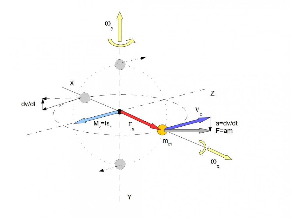 ribes
ribes
How this moment of force works during the dzanibekowa effect shows this simulation
Here is a change in angular velocities relative to body