Mass Torque System
Members
-
Joined
-
Last visited
Everything posted by Mass Torque System
-
Thanks — I’ve added the full written information to the post.
-
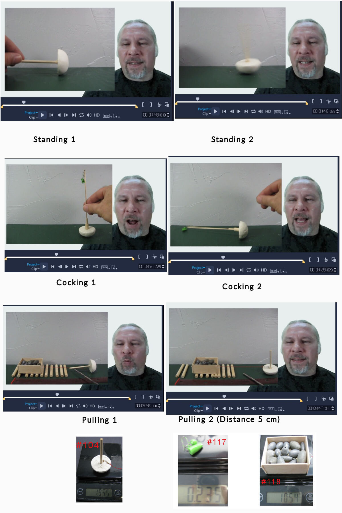
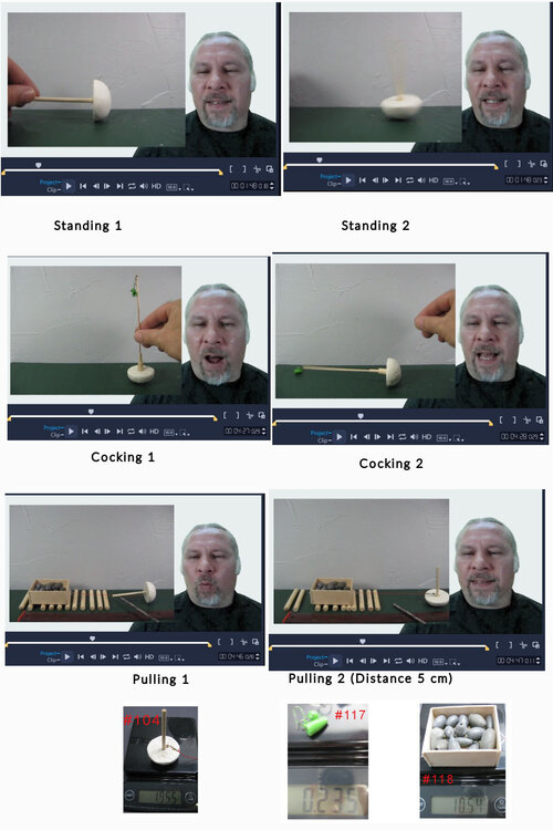
Episode 2 of the Mass Torque System focuses on the basic cocking motion shown in Figure 1 and explains how the mechanism behaves partly like a second‑class lever while also using gravity to assist the motion. The episode describes how the lever is pulled downward, how the rounded base begins to rock, and how the system reaches the balance point where gravity completes the motion. It also covers how the engine stores gravitational energy in its cocked position and releases it in a single strong power stroke, contrasting this with a normal lever that does not assist its own reset. Several comparisons are made to familiar tools such as come‑alongs, prybars, and trebuchets, highlighting the differences between single‑release devices and a system designed for controlled, repeatable cycles. The episode includes demonstrations of moving and rotating the engine, using it as a wheel, forming rigid or flexible axles from paired engines, and running both high‑torque and low‑torque tools at the same time. It shows how traction affects performance, how the engine can crush material, and how very small weights can pull much heavier loads when routed through the system. Some of the ideas explored in this episode were shaped by discussions taking place in this forum and others, especially regarding lever comparisons, balance points, and the role of gravity in the cocking motion. The episode closes with broader applications such as quarry work, continuous low‑energy tools, and the possibility of using everyday downward travel to automatically cock the system. Here is the second episode: Mass Torque System — Episode 2: The Mechanics Behind the Engine - YouTube
-
I agree that the sled isn’t being lifted and that rolling on rollers takes a lot less force. I’m still learning the math behind all of this, so I don’t fully understand everything yet, but I’m sure you’re right that the work out can’t be more than the work in. Hopefully one day I’ll be able to express all of this in better mathematical terms. No, I’m definitely not a math expert, but what you’re describing makes sense to me in a practical way. This tool I’m working on does seem to have a lot of the behavior you’re talking about — especially when there’s some slack between the sled and the machine. When the line finally goes tight, the engine gives that heavy, short burst you mentioned, almost like a snap‑action release. I’m not exactly sure how to tie all of this together mathematically, but I can definitely understand the concept of impulse and how a force that acts over a very short time can feel much larger than a steady pull. If you have more to add or think there’s a clearer way for me to measure this, I’m all ears. You’re right — that’s exactly the issue I’m running into. I realize now that I should have been measuring the horizontal pulling force instead of treating it like a vertical lift. I just haven’t figured out an easy way to measure that yet with the tools I have, but I’m working on it. I’m trying to come up with some simple experiments that will help visualize the actual force the engine is producing when it pulls the sled sideways.
-
Here are the mathematical equations I’ve put together for the full input‑and‑output cycle of the Mass Torque Engine. I’m still learning the proper terminology, so please feel free to comment or correct anything. Input (cocking the lever): Force: 0.23 ounces Distance: 14 centimeters Time: 1.0 second Work_in = 0.23 × 14 = 3.22 ounce‑centimeters Power_in = 3.22 ÷ 1.0 = 3.22 ounce‑centimeters per second Output (sled being pulled): Force: 10.5 ounces Distance: 5 centimeters Time: 0.8 seconds Work_out = 10.5 × 5 = 52.5 ounce‑centimeters Power_out = 52.5 ÷ 0.8 = 65.63 ounce‑centimeters per second Ratios: Work_out / Work_in ≈ 16.3 Power_out / Power_in ≈ 20.4 Based on these measurements, the output work and output power appear much larger than the input values. I’m not claiming anything unusual; I’m just trying to understand how to interpret these numbers correctly. It may be that I’m missing something about how energy is stored or transferred inside the mechanism, or that I’m not accounting for all the inputs properly. I’m still learning, so any feedback from people who understand the physics better than I do would be appreciated. Thanks for bringing that up — the hydraulic comparison is a helpful way to frame the discussion, and I appreciate you mentioning it. It lines up with some of the ideas I’ve been exploring, even though my setup isn’t hydraulic. Your comment still helped move the conversation in a useful direction, so thank you for that. Thanks for the examples — they actually help frame the idea in a more familiar way. The toilet flush and the pumped‑storage system in Wales both show how energy can be gathered slowly and then released quickly to create a much stronger effect. That’s the same general concept I’m exploring here: a small input over a longer time can be reorganized by the mechanism into a larger output over a shorter time. The details are obviously different, but the principle of concentrating energy is similar. I appreciate you bringing those examples into the discussion. Thanks for the feedback — I understand what you mean. The single picture definitely doesn’t show the whole process, and the force‑over‑shorter‑distance part only becomes clear when you see all the steps together. I do have a demo video that walks through the full sequence in better detail, along with a link to the patent/Youtube roadmap where the entire system is laid out. I also posted the mathematical equations a few posts back, which break down the input and output numbers we measured. If you get a chance to look at those, I’d appreciate any suggestions or corrections. I’m still working on presenting everything clearly, so your comments are helpful. Youtube Demo Video: Unlimited Power: A Breakthrough That Explains Ancient Secrets Ep.1 - YouTube Patent/youtube roadmap: https://docs.google.com/document/d/1vAlkF8iXIY9g8FTanWJ8heeNnhAQz6hiXsdYH59faXc/edit?usp=sharing
-
Thanks for the question. I’m not claiming to violate energy conservation, and I’m not pretending to have all the math worked out. What I’m showing is that in my demonstration, a 0.2 oz input weight was enough to cock the mechanism, and that stored setup then moved a 10.5 oz sled. When I talk about a “larger mechanical output,” I mean that a small input force applied over a longer distance or time can set up a system that later produces a larger force over a shorter distance. That’s a normal lever principle — the same idea behind come‑alongs, ratchets, and other tools that let you trade distance for force. So I’m not saying energy is created. I’m saying the mechanism stores the input in a different form and then releases it in a way that produces a higher instantaneous force. That’s what I’m experimenting with and documenting. Yes, it’s been offline for me for a few days too. And thanks for the reply. I don’t have much of a mechanical background, and I’m still learning things like Newton’s laws, mechanical advantage, velocity ratio, and all the proper terminology. Most of what I’m doing is hands‑on experimenting first and then trying to understand the theory behind it afterward. The examples you mentioned are helpful. I get the general idea of how torque and lever arms show up in different systems, even if I’m still learning the formal terms. I’m just trying to connect the theory with what I’m seeing in my experiments.
-
Thank you for your thoughtful post and for pointing out other examples of machines that combine levers and rotation — those are great references. I’ll start making a list of these kinds of contraptions for future discussions, since they spark new ideas. A few that come to mind are buoys, trebuchets, and even crowbars to a certain degree. I can’t prove the ancients used systems like this either, but it’s the best explanation I’ve come across that gives them massive torque and raw power for lifting, cutting stone, or even powering plows and other practical applications. The folding wedges you mentioned remind me of some of the experiments Wally Wallington was doing, which is another system I’d like to explore and integrate with my own Mass Torque techniques to see what’s possible. If you get a chance, please take 11 minutes to watch the video I shared and check out Wally Wallington’s work — I’d love to hear any advice you have along the way. Thank you for adding those examples — the ballista, the slingshot ballista, and the atlatl are excellent illustrations of how these principles were applied in different contexts. I’ll add them to the growing list we’re keeping for future discussions and ideas. It’s really helpful to see how many variations of these mechanical concepts existed across cultures, and I think comparing them will spark even more insights as we continue exploring. Haha, I appreciate the clown example — I’ll keep that in mind in case the Patent Office decides to get creative with prior art citations! Thanks also for pointing out the fundamentals of the counterweight principle. You’re absolutely right that the work output is tied to the weight multiplied by the vertical distance of the drop, ignoring losses. Where my Mass Torque system builds on that is in how the device is cocked and then released to generate torque. The design allows a small input (like a modest electrical rig or manual effort) to reset the system, while the release produces a much larger mechanical output. That’s the raw power I’m focused on — something that could be applied to lifting, cutting stone, or even agricultural work. I’ll be detailing more about how the torque is generated soon, but I really appreciate your interest and the chance to discuss the mechanics step by step.
-
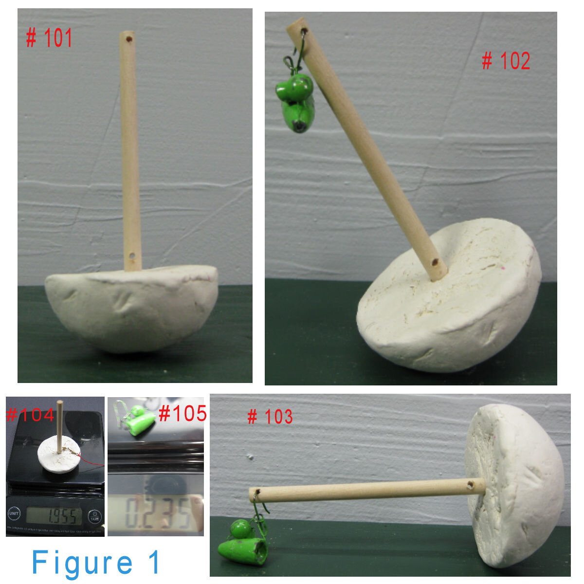
Thank you for your interest and for clarifying the video rules — I’m new to this site and appreciate the guidance. Instead of linking to a video, I’ll be referring to the patent information I’ve already prepared, which includes clear explanations and supporting diagrams. My goal is to present the concepts step by step so the mechanics are easy to follow, without overwhelming anyone with too much detail at once. I’ll start with the fundamentals and build from there." Title: Mass Torque System Featuring the Masstorque Engine [0001] Field of the Invention: This invention relates to mechanical systems for torque amplification, locomotion, and load manipulation using gravitational mass displacement and leverage. It specifically pertains to a modular engine capable of lifting, moving, positioning, and powering mechanical systems without reliance on motors, hydraulics, or conventional external power sources. [0002] Background of the Invention: Conventional lifting and transport systems rely on powered actuators, combustion engines, or hydraulic systems. Ancient civilizations, however, constructed massive monuments using unknown or lost mechanical techniques. The Masstorque Engine revives and modernizes these principles, enabling a small group—or even a single operator—to manipulate objects many times heavier than the device itself. The simplicity of the system suggests that similar principles may have been used in antiquity, enabling monument construction and heavy transport under conditions where conventional machinery was unavailable. This invention offers a scalable, low-energy alternative for construction, agriculture, and mechanical work. [0003] Summary of the Invention: The Masstorque Engine consists of a half-dome mass element resting on its curved surface, with a rigid vertical leverage arm extending from the center of its flat edge. The system uses gravitational force and controlled oscillation to generate torque, which is transmitted through the leverage arm to perform mechanical work. Through modular configurations, the engine can walk, pivot, climb, roll, saw, plow, float, and even drive turbines for electricity generation. [0004] Naming Note: For clarity, the term Masstorque Engine refers to the core invention—the half-dome mass element and leverage arm system that generates torque through oscillation. The term Mass Torque System refers to the broader ecosystem of applications, auxiliary tools, and configurations built around the engine, including guidance frames, stone tools, agricultural implements, aquatic transport, and modern generator hookups. Together, these names distinguish the foundational engine from the extended family of technologies it enables. [0005] Drawings will include: Core engine geometry and labeled components Locomotion configurations (walking, turning, ramp climbing) Load manipulation setups (lifting, dragging, rotating) Tool integration examples (sawing, grinding) Floatable configurations for aquatic transport Guidance systems (Straight Guide Frame, Curved Guide Frame for steering) Engine variants (Half-Dome, Flat-Dome, Square-Basin geometries) Auxiliary stone tools (Balance Stone, Lug Stone, Brake Stone, Lever Stone) Agricultural applications (Torque Plow, Torque Scythe) Modern applications (Torque Turbine and Generator Mode) [0006] Figure 1 is a composite image showing three sequential views of the Masstorque Engine: #101 – Upright, neutral position: The engine consists of a semi-circular base (hereafter “Stone Base”) with its curved side resting on the ground and a vertical leverage arm (“Torque Pole”) extending from the center of the flat surface. #102 – Initiation of torque cycle: A counterweight (“Countermass”) equal to approximately 1/10 the engine’s mass is attached to the top of the Torque Pole, initiating a controlled lean. #103 – Cocked position: The Torque Pole is now parallel to the ground, having been pulled down by the Countermass. The system is primed for force transfer via rope or linkage. #104 – Mass measurement of the engine: A digital scale reads 1.995 oz, confirming the mass of the Stone Base and Torque Pole assembly. #105 – Mass measurement of the Countermass: A digital scale reads 0.235 oz, confirming the 1/10 ratio used to initiate the torque cycle.

-
I’ve been exploring how geometry, mass, and gravity might have been applied in ways we don’t usually consider. The Mass Torque System is my attempt to model how small inputs can leverage large outputs through controlled torque and balance. In a simple demo, .23 oz of input force moves a 10.50 oz sled — a 4565% increase. I’m not claiming new energy is created, only that mechanical advantage can be harnessed in a novel way. Could principles like this have been used in ancient construction methods at sites such as Cusco, Baalbek, or Puma Punku? I’d like to open this up for discussion — do these mechanics resonate with known physics, or might they point toward overlooked applications? Note to moderator: Please move this thread to the most appropriate section if needed. Demonstration video: Unlimited Power: A Breakthrough That Explains Ancient Secrets Ep.1