JemJem
Members
-
Joined
-
Last visited
-
-
Here is the full breakdown from ChatGPT: 🔌 Series Strings and the Weakest Link ProblemIn a series-connected string of solar cells: The same current must flow through all cells. If one cell is shaded, it becomes the bottleneck. Even if it produces some power, its lower current output limits the whole string. That’s why shading even a single cell can drag down the performance of the entire series — it’s not just about contributing less, but actively restricting the flow. 🔥 Why Bypass Diodes Are NeededWithout a bypass diode: If a shaded cell can't pass the current demanded by the string, it becomes reverse-biased. It starts dissipating power as heat. This can create hot spots, damaging the cell or panel. With a bypass diode: Current flows around the shaded section. The rest of the string can continue producing power, only losing the shaded section's contribution, not the whole string’s. So, the diodes aren't "blocking" good energy, they allow the rest of the system to keep working efficiently. ✔️ Responding to Your Quotes1. "Shaded cells still contribute some power"Yes, but: Not enough current → bottlenecks the string. Can still become reverse-biased → heating risk. Partial shade can still cause major losses if bypassing isn’t allowed. 2. "Built-in diodes are blocking diodes"Partially incorrect: Diodes inside panels are mostly bypass diodes. Blocking diodes are typically used externally (e.g. in charge controllers or panel outputs) to prevent reverse flowfrom batteries at night. 📊 With a Single DiodePanels with only one bypass diode (across the whole panel) are less efficient under partial shading. If only 1 out of 3 cell strings is shaded, that one diode has to bypass the entire panel, losing more potential output than if there were multiple bypass diodes. ✅ SummaryShaded cells = weak link → lower string current. Bypass diodes = allow current to bypass problem cells → maintain performance & safety. Multiple diodes = finer control, less output loss. A panel with only one diode loses more power when even part of it is shaded. Let me know if you'd like a diagram to clarify the current paths with and without diodes. Before I gave the abridged version. This should be correct ?
-
I have no idea. I only posted what I had to explain that using diodes on a parallel circuit would allow for greater solar panel efficiency.
-
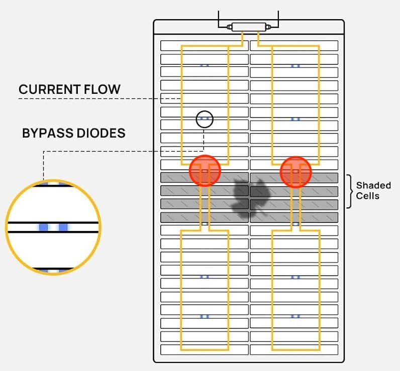
SERIES STRINGS AND THE WEAKEST LINK PROBLEM In a series string of solar cells, the same current flows through all the cells. If one cell is shaded, it limits how much current can pass through the whole string. Even if that shaded cell still generates some power, it restricts the flow for the others. This means a single shaded cell can reduce the output of the entire string. It's not just about contributing less — it becomes a bottleneck. WHY BYPASS DIODES ARE NEEDED Without a bypass diode, a shaded cell may not pass the current required by the rest of the string. When this happens, the cell becomes reverse-biased. It starts to heat up and can create hot spots. This heat can damage the cell or even the whole panel. With a bypass diode, current can flow around the shaded cell. The rest of the string keeps working normally. Only the shaded section is taken out of the circuit. This keeps the panel safer and more efficient. The diodes don’t block useful energy — they help preserve it by preventing one bad section from dragging down the whole system.
-
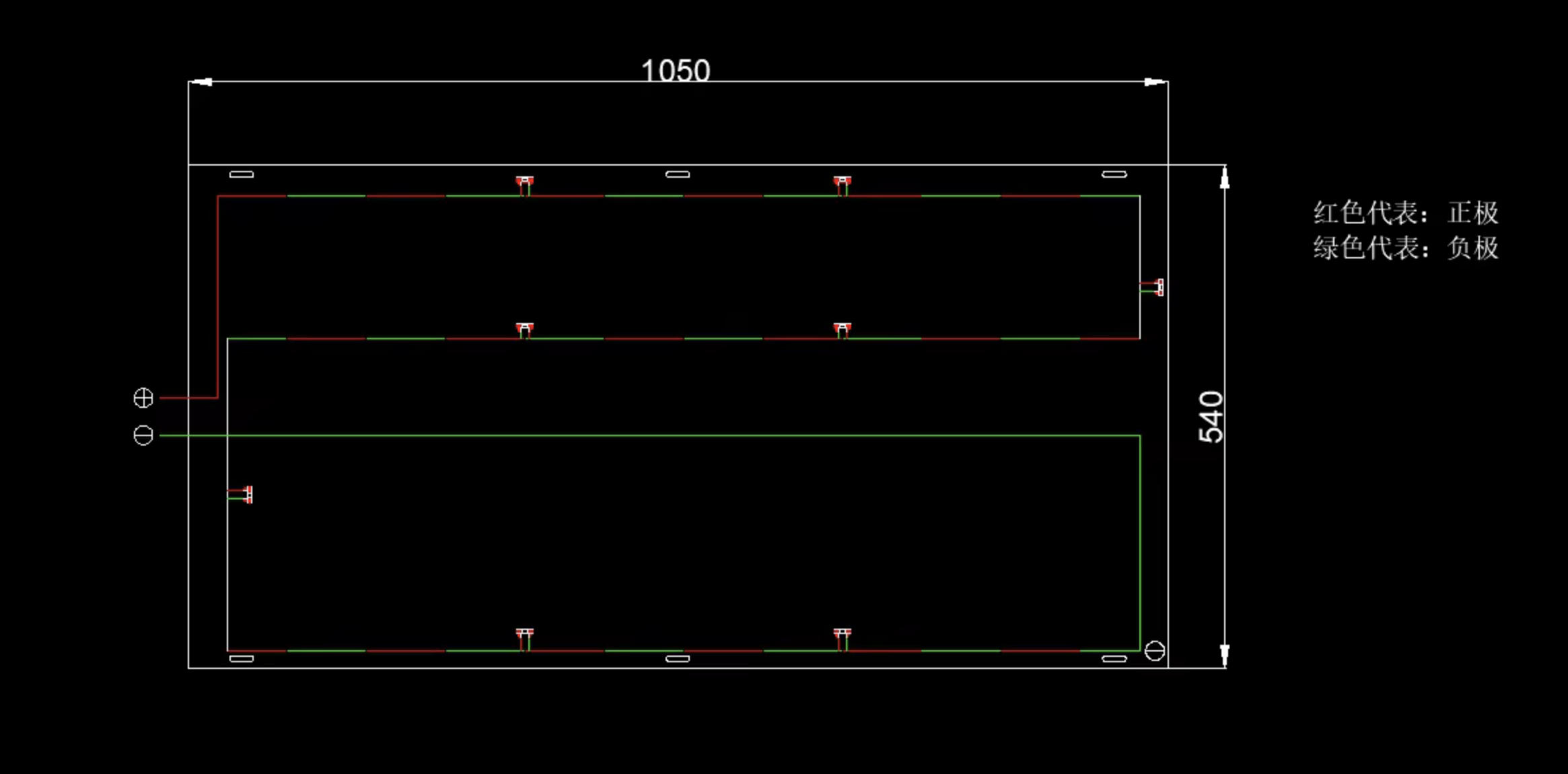
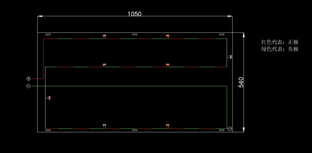
@studiot I gave that a bash, just for illustrative purposes. But it's an ugly representation, which is what led me to come here to better understand the matter. @studiot Unfortunately, the best diagram that I could get was the black one with the red and green lines. @npts2020 Apparently, panels with only one bypass diode (across the whole panel) are less efficient under partial shading. So if only 1 out of 3 cell strings is shaded, that one diode has to bypass the entire panel, losing more potential output than if there were multiple bypass diodes. @toucana Useful info, thanks. @studiot This was something that interested me, as daisy chaining a 200W panel to a series of 100W ones would not necessarily play nice - something that I still need to look into. As for the diode placement, I think that it cannot be honed into an easy to grasp graphic and shall just go along the same lines as the example that I gave where everything neatly ties up.
.thumb.png.9f632b09baf5633b4d21f2bdeb2de844.png)
-
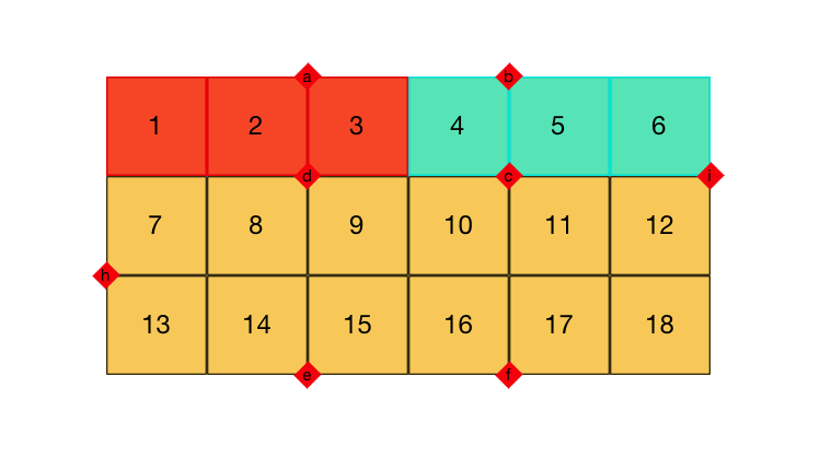
I am having trouble understanding how a parallel circuit actually works, on paper. Below is a cluster of solar cells on a panel with strategically placed diodes so that each cell can work independently to its maximum if part of the panel were shaded: First of all I need to know if that concept works (I just assume that it does because others sell such panels), over a serial design where a portion of the panel being shaded would simply reduce the entire panel's output, thus making it less efficient, but cheaper to produce. Presently there is a single diode inside the junction box (not illustrated with a circle, at the left of the illustration i.e. top of the panel), which regulates the entire panel. So were this to be daisy chained then it would serve the same purpose, but on a far larger scale. Assuming that the extra diodes would allow the compartmentalised cells to perform to their maximum independently I need to understand the following diagram of how they fit together: I have attempted to simplify the system (for illustrative purposes), but the placement of the diodes doesn't make that easy to understand: Imagine if cells 1 and 7 were shaded by tree cover, how do I tie that in to any of the diodes ?! Although other examples online seem to better communicate this, they do not bear resemblance to the actual placement of the diodes. This would be easy for me to emulate, but I still wouldn't understand how it really worked and that is a missed opportunity: I need some help guys.
.thumb.png.702d250eb7636ce0fd42b361ada09064.png)
.png.3e4334e3069959cc04cdb54091532160.png)
.png.64f19a3c6c3e214b9c183b6d8d421d57.png)