


Sandor Szekely
-
Posts
33 -
Joined
-
Last visited
Content Type
Profiles
Forums
Events
Posts posted by Sandor Szekely
-
-
Exactly, thank you.
Do you realise that geoids, spheroids or any other oids (droids, androids etc) are quite irrelevant to your work?
You would have to perform a deal of calculations to refer the actual measurements you take to any of these.
The first thing an engineer would have to do, if asked to place a giant curtain across the lake, just touching the water surface, would be to undo all those calculations to obtain real world measurements.
Please confirm some things before I answer the other parts of your post.
You did say that you have a degree in mathematics did you not?
So I have assumed you can easily substitute values into the formula given in the left hand page of my extract from Wild.
So you could generate your own table and check the calcs for yourself.
The derivation is simple enough it only requires first or second year high school geometry.
Please say if you are having trouble with the technical English (I thought yours was pretty good).
But yes, at 4.9 kilometers sight distance the combined addition for curvature and refraction is 1680 mm.
The curvature alone amounts to 1885mm.
But the question is, what do you intend to show with this value?
I don't have a degree in math, but I get along well

I worked as a cameraman long time ago and became an inventor 2 decades ago.
I get along with technical English, but I am thankfull if you correct me! I use dictionary to search terms that I am not familiar with, but I may use them incorrecty.
"the combined addition for curvature and refraction"
thanks this makes it perfectly clearly understandable
I'd like to calculate the amount of curvature that we are looking for, so we know what precision we have to do in our measurements. I see that it would be very hard to determine the difference of few centimeters on these distances, but looking for meters of difference should be very well measurable.
0 -
There is really only one column, but it is split into 5.
Within each of the 5 'columns' the combined curvature and refraction correction, as calculated from the formula given on the preceding page, is tabulated on the right hand side against the sighting distance D.
D is in kilometers, the correction is in metres.
So for instance the first 'column runs from a distance of 100 metres (=0.1km) to 1000 metres (=1 km)
At a distance of 1km the correction is given as 0.07 metres = 70 mm.
I'm sorry to hear you were ill (not too much Bull's Blood I hope?
)Unfortunately you seem to have been reading in the wrong places about refraction.
Refraction affects both vertical, horizontal, and true distance measurement as well as angular measurements.
Further the effect depends upon the type of EDM and measurement employed.
Consequently there are many formulae, each for different purposes and you need to be something of an expert to chose the right one.
I do not intend protracted discussion about refraction here since it small in your case and largely irrelevant.
Further it can be eliminated by proper observational methods, as I keep saying.
One interesting point is that the variation of refraction with the frequency of the EDM leads to a phenomenon called dispersion which allows accurate measurement of the refraction over the whole observed line of sight with polychromatic light.
Monochromatic sources do not allow this but special two colour laser systems such as 'Georan' are available to exploit this.
Another irrelevancy is the CCD issue.
Charge coupled devices are much older than their use in solid state cameras.
They were originally introduced to facilitate digital signal processing for instance in filters and delay lines.
My brother-in-law did his final year project on Digital Filters in the late 1970s.
Optical applications came a decade later.
So, back to the project in hand.
Your objective is to measure the actual shape in space of the surface of the lake, is it not?
You should be aware that the surface of water bodies on Earth is rarely level, flat, equipotential etc.
In hydraulic engineering we consider something called the 'backwater curve', whcih is the shape of flowing water surface as it approaches an obstruction.
This curve can even include actual physical steps in the surface, known as hydraulic jumps.
The surfaces of main oceans of the Earth (Atlantic, Pacific, Indian and Southern) are not at the same 'level'.
This does not go as far as jumps or step changes but manifests itself as a region of turbulence where they meet.
The so called 'cape rollers' off South Africa are an example of this.
Returning to the actual shape (and size) of the water surface at Lake Balaton,
Do you fully understand the difference between actual on site measurements and the 'reduced measurements' you would plot on a spheroid or geoid or a map?
This is very important and would help greatly in your discussions with your surveyor.
Would you like me to explain the difference between the terms level, equipotential, spheroid, geoid etc ?
I have a confusion here:
your chart says 4.9kms is 1.68 meter
the curvature of earth in the 4.9 kms distance is 1.88 meter.
so is the refraction here 0.2 meter or 1.68?
"I do not intend protracted discussion about refraction here since it small in your case and largely irrelevant."
in the case of 0.2 meter, maybe but I still don't see how it can be standardised as it deends on the local condition change.
"One interesting point is that the variation of refraction with the frequency of the EDM leads to a phenomenon called dispersion which allows accurate measurement of the refraction over the whole observed line of sight with polychromatic light.
Monochromatic sources do not allow this but special two colour laser systems such as 'Georan' are available to exploit this."
Please tell me more abut this, I think this is exactly what I figured out with the dual colour laser too. So as I understand there are eqiupment like this?
"Your objective is to measure the actual shape in space of the surface of the lake, is it not?
You should be aware that the surface of water bodies on Earth is rarely level, flat, equipotential etc."
My objective is to find out the shape of the water surface, if it is flat or curved.
I think there is a huge difference in the outcome of the 2 models already at a shorter distance of 10kms, and a huge difference on the 77kms of the lake. This should be significant enough to exclude one of the models. I am not aiming to make the most precise measurement just to the accuracy that we can determine the shape of the surface: is it flat or curved?
Is it possible to have 465 meters drop of curvature on the lake Balaton?
Yeah maybe some Bull's blood would be good for me
but I never drink alcohol 0 -
That's not true. I have used many ccd and CMOS sensors during my time as a professional optical physicist with no attached lenses at all. The coolest was liquid nitrogen cooled to detect very low intensities.
You also need something with really accessible and understood electronics to actually measure the intensities. Not some processed output as you get from a camera.
Your set up as is is not good enough to find the centre of the beam.
We will use a board big enough to capture the whole beam in the upcoming experiment. Way more easy than to get the same size of any detector.
temperature is such that de
My question is : how can anyone estimate, or use a standard value for terresterial refraction?
Refraction is caused by change in ambient conditions like pressure, temperature, density or humidity (...)
In the case of atmospheric refraction, light coming from thousands of miles from vacuum through more dense, humid, warmer and pressured air it has a well definable "standard" value. Change is more-less the same.
But in the case of terresterial refraction like in our experiment the laser beam is going within a short height difference above water, conditions are nearly the same all the way. In this case the refraction can not be pre-determined as it depends on local changes.
Refraction is also not a curve but a bend at certain points (where conditions change) and connected with straight path of light.
So in my opinion terresterial refraction can only be measured, but not calculated with a standard formula.
What is your opinion on the best way to measure it?
(mine is to use different colours, but we did not have the collimator for the 2nd)
0 -
Er No.
The problem is that I don't think you understand the surveying theory.
I seriously doubt that the Swiss authors were referring to a standard correction as we are discussing.
Since they mention double run leveling, they are talking about calculational adjustments to a leveling network.
I make the refraction correction 11mm not 0.4mm at an observational distance of 1000m
Here is a proper Swiss discussion, including a table which includes refraction and curvature corrections.
Note carefully their value at 1km. They make the refraction correction 9mm using a slightly lower value of refraction that the international standard constant of 0.07, but still very close to my calculation.
This is taken from the Swiss manufacturer's textbook
The Theodolite by Wild of Heerbrugg Switzerland.
This lack of surveying knowledge may also have lead to you abrupt response to my posts on reciprocal levelling (post#137) and the previous one (post#133) on survey control points.
This is why I keep recommending obtaining the services/advice of a professional surveyor.
Hello Studiot
I've been sick for the last days therefore had a lot of reading on the refraction subject.
Please note here at end of page 26
"Assuming 17 levelling setups along a levelling line of 1 km, the total systematic devia¬ tion caused by refraction is 0.75 mm/km. For comparison: the standard deviation of height differences obtained by precise levelling using digital levels is about 0.3 to 0.4 mm/km (double run levelling) as reported, e.g., in [iNGENSAND. 1995J. There¬ fore, the refraction influences should be taken into consideration."
"In order to obtain a hypothesis-free reduction of refraction influences, it is necessary to determine the refraction influences integrally along the propagation path"
Summary of page 29
http://e-collection.library.ethz.ch/eserv/eth:23778/eth-23778-02.pdf
Please explain in your referenced table what is the 2nd column and what it is it measured in? (meter?)
In general I think terresterial refraction can not be calculated with a formula, especially not correspondent to the earth curvature. In other words: refraction has nothing to do with curvature.
In my opinion terresterial refraction can be measured but not calculated, as terresterial refraction is due to LOCAL changes. Unlike atmospheric refraction where the ambient data can be estimated and the change of conditions are more alike.
Refraction is bending the light due to CHANGE of the medium.
I see no constant or presumable change on horizontal distance measurement. It is not like sunshine coming from near vacuum and entering into more dense, humidand warmer atmosphere - where we can estimate the effects roughly.
Terresterial refraction is caused by LOCAL changes and temperature/ pressure differences, like a hot spot. That is a bending point of the laser, but NOT a continous curve at all.
At the moment I see that refraction may be measured with different color of laser beams, and it can not be estimated nor calculated.
so we have to look for theautoconvective laps rate condition:
In my opinion the laser beam is going in a straight line between the bending points, therefore that is not a curve.
The suggested laser beam refraction is 1/7th of the curvature in this example on this page (or the horizon distance is +7%)
http://mathscinotes.com/2013/08/distance-to-the-horizon-assuming-refraction/
here some interesting data on convective stability
http://meteorologytraining.tpub.com/14312/css/14312_53.htm
A digital camera has a ccd or CMOS sensor but lots of other stuff too like lenses. That's not what you want. You want a sensor array with no optics to measure the beam power to try and find the beam centre.
Kalynos, I am a cameraman...
a ccd is a device that has lenses and other stuff too.. that is called the camera. All sensors have optics.
0 -
You've failed to address any of my comments. Only emotionally responded to one part. Did you actual read or understand my concerns about beam divergence and measuring the power in a cross section of the beam?
Opps, whitch one I forgot to answer?
I've not watched the video. I did fear this might be the case. You can get "bright" spots off of thr beam path, and you'll be killed by any beam divergence or laser wobble. I don't really think this experiment is within the reach of a hobbyist. Although it looks simple as soon as you start actually thinking about it there are so many subtleties that will make your results meaningless.
so I should answer: no I can't get "bright spots" off the beam path. "killed by" what is that term?
"Although it looks simple as soon as you start actually thinking about it there are so many subtleties that will make your results meaningless."
what does this sentence mean? you say surface can't be measured with laser? well... this is your opinion and I have mine
That's a terrible way to measure. You could do something similar with a camera sensor but where you measure the intensity from each pixel. But you'd need a large area CMOS or ccd and some clever way of removing ambient light.
IS that a terrible way? LOL have you seen Stephen Hawking Genious video (attached here before)?
my favourite part:
But you'd need a large area CMOS or ccd
a digital camera IS MADE OF A CCD
please point me to your important suggestion, it looks like I did not find it
0 -
Here is my first stab at putting this into a spreadsheet:
https://drive.google.com/open?id=0B22sA7_PYGQvMFY5WWtIenU0ZVk
Assumptions: WGS84 ellilpsoid
f=1/298.257223560
a=6378137.000Radius of Curvature at latitude θ ~ a(1-f sin²(θ))That the top of the black tape mark is ~1.185m as estimated by Mick West's analysis.The slope calculation is against a flat baseline calculated between the laser itself and measurement point C4, where they re-leveled the laser.ΔGround[2.286] + laserHeight@C4[1.185] - laserHeight[1.25] / distance@C4[720] = ~0.003084 meters per meterYou can use column T to ignore the beam width or column U attempts to find where the bottom of the beam might be.Beam divergence angle for C0, C1 is just set to same value as C2 as I don't have good values - the values in green are actual estimates, the values after that are extrapolated but conservative estimates from the green values only.No refraction is taken into account.Unfortunately the data is not clean enough to do a 'fit' analysis. But this does align well with the first few measurement points, accounts for the beam spread and later reflective hits.Using simple curvature did NOT fit the observations well.Thank you.
By 'Gaussian beam divergence' I just mean the amount of divergence expected from a laser beam given some degree of collimation, even in a vacuum. This beam is spreading at an increasing rate of divergence rather than some fixed divergence angle. So I think that atmospheric effects are dominating. Some of that is diffraction, some is refraction - but end result is that the spot we see at C1 and C2 has grown considerably by C4 and by C11 it's so spread out we can barely see it on the board.
If you assume an ~100mm aperture (hands width) at the start and try computing the divergence angle at each of C2, C3, C4, & C5 you get different answers for each distance -- so it's not a constant rate of divergence (or maybe the distances are wrong but I think it's too great for this to be the only cause). These are the measurements that I'm referring to and I posted a montage showing these in my earlier post:
426m shows ~25cm diameter of spread
631m shows ~31cm diameter of spread
720m shows ~48cm diameter of spread
870m shows ~72cm diameter of spread
I think your calculation is far off from reality. PLease explain that excel with words too:
you suggest, that at c37 6000meters: beam diameter is 11.75 meter?
you say, that the calculated bottom of the beam is at -2.97 (meter?)
How is that possible?
then it should be visible on the board and it shall hit the water
NONE of that is recorded...
Please clear your calculations.
your calculation is way wrong starting with a false assumption on the leveling.
C1 - C4 is NOT measurement points.
How do you come to this divergence calculation anyway? do you realize that the beam was reflected from the metal frame and therefore it spreads the beam?
"This beam is spreading at an increasing rate of divergence rather than some fixed divergence angle. " how did you come to that conclusion?
I think your calculation on beam divergence is way wrong
0 -
From the given data, it looks the Balaton lake is not level. It flows like a river. It has a level +150.55 at inflow (left on the picture) and 149.65 at outflow, a difference of 90cm from level.
 post-120902-0-23645600-1473549296.jpg
(I have added labeling on the maps provided in the OP)
The experiment was taken at a point after a bottleneck, transverse to the lake. From the color legend, the lake shows a slight level difference transverse also.
If the experiment has been correctly conducted, then the surface lake is concave along the experiment. Eventually the concave of the lake surface and Earth curvature would cancel each other and gives an almost perfectly flat section.
But that would be a extraordinary coincidence that a F.E. knew about this and decided to take an experiment right at this spot and at the right time of the year.
Michael you are wrong.
Read through the lidar experiment again, Balaton lake DOES NOT flow like a river. It is a "trully level surface".
" It has a level +150.55 at inflow (left on the picture) and 149.65 at outflow, a difference of 90cm from level."
Very wrong and missleading.. NO the highest point of the lake is NOT at the inflow, and the lowest point is NOT at the outflow. (just to tell you for a less "misspresentation of the lidar experiment" I have been banned from an other forum...
amm... just to inform You all: the RIVER Danube has a 26 cms drop over the COMPLETE route in Hungary. You say seriously that the lake has 3x more on a distance of 1/10? lol
!Moderator Note
As has been previously pointed out, you need to present enough information for discussion here, so that people need not watch the video to participate.
!Moderator Note
You can do that without the histrionics. But the price for using this platform to discuss your experiment is answering criticism about the experiment
As a moderator I think you should be concerned to avoid discussions like this from the forum:
"I suppose so it's just there to catch attention to YouTube video, to earn money on advertisements from Google.
Scientists seeking for the truth don't behave like that. "
IS this personal or has to do with the experiment evaluation?!
0 -
equipment datasheets are definitely handy. I can also use them to look for some of these affects mentioned. The effect of the elevator duct varies depending on equipment frequencies. Glad to see someone that can help double check the equations involved for this application. I'm going down memory lane on everything involved, in terms of refraction, scatter etc.
The more I think of this test, the more I keep thinking that two emitters may be a good idea. I keep looking at the pros and cons involved. Assuming parallel transport placement. Safety issues addressed (lol). KEY NOTE use two distinct frequencies.
PROS.
1) detection in deviation in parallel transport can be used to find changes in refractive index.
2) if the two lasers are mounted in tandem vertically we can use geometry relations between the two beams to assist in leveling. Combined with a grid backboard we can break the leveling aspects down to straightforward trig. This will help correct leveling errors in 3D if done correctly
3) the changes in frequency and loss of parallel transport can be used to calculate the refraction index. (this in principle is used in equipment today. Usually through a known sample) however a known sample isn't needed just more complex. If not.
CONS
1) added equipment and complexity, adds to potential systematic errors
2) greater number of control point data to collect. (measurements between the two laser beams for example, as well as receiving frequencies.)
Even without worrying about refraction, etc the advantages in PRO 2 is in my opinion worth the added cons
The above may work better if the two lasers were aimed to a common point. Forming two sides of our triangle, this can help in leveling and distance from emitter calcs.
(KEY NOTE do not mount the two lasers onto the same mount backboard. We don't want to add material expansion/contraction problems)
Hello Mordred
We did think about using dual colour laser (and used it on the pre-test) to calculate reftraction by the difference of the blue / green beam. The cons are not a problem, indeed I'd like to add more types of equipments to improve the measurement accuracy.
Actually we have only one problem with this: we have only 1 collimator that is on the green laser. We might be able to get an other one too.
Could you please explain this in greater details?
"The above may work better if the two lasers were aimed to a common point. Forming two sides of our triangle, this can help in leveling and distance from emitter calcs.
(KEY NOTE do not mount the two lasers onto the same mount backboard. We don't want to add material expansion/contraction problems)"
Did someone say that this is one of those laser projecters used for creating vector images through a series of mirrors? Could it be that it is always being reflected and that one of the mirrors is wobbling/vibrating?
no, wedo not have laser scanner (mirrors) in this laser unit.
As I pointed out, the horizontal vibrating effect was due to the laser beam hitting the water surface at the 3rd measurement (reflexion)
I think these extracts show the confusion between a flat surface and a level surface.
A level surface is most definitely curved, a flat surface is essentially planar.
So how can a flat water model be consistent with laser or any other leveling?
I think there is a confusion on the meaning of "level". Here are some definitions, copy Nr1 here:
"Level \Lev"el\ (l[e^]v"[e^]l), a.
1. Even; flat; having no part higher than another; having, or
conforming to, the curvature which belongs to the
undisturbed liquid parts of the earth's surface; as, a
level field; level ground; the level surface of a pond or
lake.
[1913 Webster]"
http://onlinedictionary.datasegment.com/word/level+surface
I've not watched the video. I did fear this might be the case. You can get "bright" spots off of thr beam path, and you'll be killed by any beam divergence or laser wobble. I don't really think this experiment is within the reach of a hobbyist. Although it looks simple as soon as you start actually thinking about it there are so many subtleties that will make your results meaningless.
That's a terrible way to measure. You could do something similar with a camera sensor but where you measure the intensity from each pixel. But you'd need a large area CMOS or ccd and some clever way of removing ambient light.
Okay so you have NOT watched the video? then what are we arguing about?
"not within the reach of hobbist"... come on.. please be more serious in commenting the experiment!
I watched the all 27 minutes of the video yesterday.
And honestly must say, you spend the more time flying helicopter and playing volleyball than thinking and preparing for gathering data during the experiment.
From your's precalculations of globe curvature there is visible that from 1.25m it will go to 4.32m,
and what size of "target" you were using?! That's has barely 2m width and 1m height.
It makes completely no sense to me at all.. ?!
(If I would be expecting melting some metal at 1000 C, would I use container that has melting temperature at 200 C?)
Additionally target was mounted at angle.
IMHO you should mount it as perpendicular to the ground of boat as possible using spirit level..
If you would be seriously going to take this experiment, you should print grid on paper with 1 cm x 1 cm spacing,
with some 10cm x 10 cm with slightly different background color (and/or chessboard), with printed numbers on side.
With size 2m width, and 5m height. To be able catch the all laser positions on it.
Mount it steadily to the boat using spirit level to be sure angles.
Mount steadily camera (better 4K,60 FPS+) in the front of target, and filming it all the time, without breaks, and as fast as possible, to have weather influence as small as possible.
(target, boat and recording camera should be each other not moveable during the entire experiment)
Captain should be controlling boat looking at laser spot, and trying to keep it in the center of target. Don't do sharp movements.
Reading results do in hotel room, looking at where is spot on target with grid, on the video recorded by camera.
Nobody serious is doing measurements in the middle of experiment, instead store data by electronics devices.
(The guy using tape measure, I could not believe my eyes.. completely unprepared people for experiment.. you looked like the first time in life doing physical experiment)
And obviously REPEAT it several times.
Additionally this "flat earth" mentioned everywhere in the video.
It will obviously put you in "crackpot zone" if you will be going to discuss experiment with other scientists.
I suppose so it's just there to catch attention to YouTube video, to earn money on advertisements from Google.
Scientists seeking for the truth don't behave like that. At least should not.
You didn't confirm that Earth is flat, but that photons from laser flied curved trajectory, at most.
And identify source causing bending of the beam.
Flat Earth + photons going straight line will have the same (or similar) results as curved globe Earth + photons going curved path.
And obviously REPEAT it several times.
With different conditions, with different time of day, and different time of year..
Sensei, I did not answer this post because I found it unrelevant and unpolite.
you asked for it so I'll answer.
"And honestly must say, you spend the more time flying helicopter and playing volleyball than thinking and preparing for gathering data during the experiment.
what is this very first sentence? I'm usually not replying to intriques... helicopter was supposed to enter the measurement, but we had to cancel that due to the storm. On the 3rd (THIRD) day we made some test flights for the upcoming measurement over land.
We did not play volleyball... that is a videoclip from someone else... OMG... this is like facebook... I am here for scientific debate - I'll leave all coments like this unanswered in the future.
About the size and position of the board : I answered that already, so I will not repeat my self - look back in the comments here.
I am sorry, if you have not seen the GoPro mounted camera on the board... 4k is not need
Captain WAS doing just fine job. I see you have no idea about a real measurement...
I see you still do not understand that WE DID NOT USE the tape measure... it was at the leveling process and NOT the measurements.
I am bored to answer questions like this...
NEVER EVER AGAIN COMMENT ON MY BELIEFS!
AND
NEVER EVER mention like "It will obviously put you in "crackpot zone""
I give respect to people here and I DO WNAT THE SAME.
If it starts to be like the other forum I will leave you too...
"I suppose so it's just there to catch attention to YouTube video, to earn money on advertisements from Google.
Scientists seeking for the truth don't behave like that. "
REPEAT AGAIN: NEVER EVER TALK TO ME LIKE THAT! I AM NOT YOUR FRIEN, NOR A PARTNER. I AM GOING TO IGNORE YOU FROM NOW.
-2 -
How did you estimate this non-uniform area to be in the 50cm range? If this is only an idea to explain the "bottom of the boat seems to disappear" part, you need additional data to analyse that. The common conception would be that the bottom of the boat disappears due to the water curvature, and not refraction. I don't think that what Sandor wants to measure is the bottom of the boat, though, as that would lead to a rather different experiment, tools and planning. I would leave this "bottom of the boat" analysis to a different moment.
Additionally to the NUDTZ existance, and existing only below 50cm hypothesis, there is clearly something other than your NUDTZ taking place at 1.35m+. The trembling laser, the laser going down and reflecting back up, etc, needs to be explained and measured.
From everything that I read I though this NUDTZ idea was to explain all the erratic laser behavior during the whole experiment.
Anyway, add to my list of suggestion to forget about NUDTZ and think only about getting all the data the correct way. As someone mentioned here, try to formulate hypothesis after you get the data correct, not before.
That's great.
Don't forget any suggestions, I'd say.
If you are willing to share the next experiment setup, before or after you discuss with the university specialists, I think a lot of people will be happy to keep debating it.
I don't know about the others, but the amount of challenges (math, physics and resources) to get this "simple" experiment up and running are huge, and it's very interesting to debate what's the best way to do all of that.
I will share - and cooperate - with scienceforum on the experiment setup and methodology as I think this is in the interest of my university partner as well.
We (Zack, Steve, me) would like to have an open source measurement and a cooperation in the evaluation too - that is the reason I have the post here on scienceforum (ONLY)
and let me share with you a PBS production : Genius with Stephen Hawking. The very first part of the film starts with a laser measurement and a boat. There is absolutely no scientific approach in this film - just a mainstream TV production - as they have not given any parameters or real measurements. You might like to check this film to understand better our motives to make a correct scientific approach to the question of curvature on water surface.
0 -
1) methodology
2) human error
3) instrument error
4) refraction
in order. Every experiment has the same sequence. The corrective measures not with standing
right
1. on the methodology I think it would be good to combine different techniques. I noted suggestion on various leveling equippments already, please advise how these different techniques can be used simultainosly to improve accuracy and exclude systematic errors from the measurement. Like how could a theodolite (possibly more in different positions) help to measure the laser beam height (maybe divergence too)? In this case of multiple theodolite laser height measurement we could make the measurements at the very same time (not like the boat 2.5 hours).
Please share suggestion on this or any other possible method.
What is your opinion on measureing on the frozen lake surface? (theodolites can be placed on the surface. refraction at night time or day time? is any posiible duct?)
2. human error will be best reduced with the help from professional geodezysts
3. instrument error may be reduced using multiple techniques?
0 -
Hi, Darkstar.
As I see it, the experiment was a POC and what Sandor is trying to do here, coming to this forum, is getting ideas and suggestions on how to get it right the next time.
If the intentions are not these, then we are just wasting our time here (oh well, isn't that what an internet forum is all about anyway?
 )
)If he is currently presenting the POC as "100% proof" of anything, he is only hurting his credibility, causing the next experiment to be taken less seriously, and the uphill battle to be harder.
I see you bring a weight and lots of emotions from the 1000 posts in the other forum, but this forum is trying to be as fair as possible, given the information posted in this forum only. By saying that people here cannot see what are his beliefs, cannot see that the experiment was not accurate, cannot see that the data interpretation and presentation was biased, you are also saying that people here are clueless, what is kind of rude to be honest.
People here are showing Sandor that the amount of calculations and advanced math and physics needed to get it right is much more than what was used in the POC, and this point is well understood, at least it seems so.
You say: "Please consider beginning by trying to convince Sandor that just because a camera on the boat can SEE the laser looking back at the dock that this doesn't constitute a valid measurement of the beam center.". In this forum Sandor agreed a couple of times that the board needs to be improved for a second experiment, what seems to be an agreement that he understands that the estimation with the camera only is not enough.
The possible misrepresentation of the LIDAR paper, the title of the video, their belief, etc, I believe are not part of the discussion.
Worst case scenario, if people think he is not being honest, they will stop answering to the thread and it will be forgotten, right?
Thank You MrMarker very well summarized.
"As I see it, the experiment was a POC and what Sandor is trying to do here, coming to this forum, is getting ideas and suggestions on how to get it right the next time."
Exactly I am here for this reason, and I am very pleased with the REAL scientific approach from most of You here!
I am reading through the comments (taking the notes
) and as well organizing the real scientific team and the new measurement.Excuse me that I comment less now - I am listening carefully to the comments and I "try to catch up" with the terms and the explanations. (my profession is a cameraman)
Klaynos:
"I've not watched the video. I did fear this might be the case. You can get "bright" spots off of thr beam path, and you'll be killed by any beam divergence or laser wobble. I don't really think this experiment is within the reach of a hobbyist. Although it looks simple as soon as you start actually thinking about it there are so many subtleties that will make your results meaningless. "
Thanks for sharing your thoughts on refraction, I think this is the most important "uncertainity" factor of the experiment.
1 -
I saw the "trembling laser" video. That's a bizarre effect indeed. It looks like it's mainly going left to right only, but the light that is hitting the board is "dancing" in on itself. There is a big bright area (around 30cm wide I'd say), but there is also a huge area hitting the board that is even bigger than the board itself. Very intriguing. Do we have any optics nerd here in the forum?

Regarding the beam distortions, those are a huge risk to your data set.
If something like that happened during the night, there is no way to know what may have happened during the day. With this new information, I would say that you need to measure the beam spot every 100m or so. 500m may not be enough.
 It's too much refraction, reflection or whatever optic distortion is going on there, to guarantee the accuracy of the data.
 Different doubt though: you mentioned reflection, but that would mean that the laser hit the water at one point, is that correct? If that's the case, the laser was either pointing downwards or the crazy refraction effects forced it downwards.
Are you taking notes of all Mordred's, Stu's, mine and others' suggestions? That's quite a lot
MrMaker,
as I pointed out that this 3rd measurement at dawn (4AM to 6AM app.) was a very unusual. Later we foulnd out at modelling that our laer hit the water around 1500 meters from the shore. So this is not refraction, but reflexion!
(I named the folder reflexion on the google drive not to make confusion with the other ones)
we went off the corse of the laser path and missed the point where it was hitting the water, as we got back on track the beam was very low. In a short distance it was rising upwards and passed above our heads. From the Canon camera it looked like a huge refraction, but from the laser position it was fine.
So the horizontal trembling laser was reflected on water surface and therefore did not have vertica movements (significant).
I absolutely agree that beam distorsion is the key of the measurement precision.
Scienceforum is my notepad
I will discuss the subjects mentioned here from the forum directly with the Hungarian scientist too. Thank you for the very usefull and extensive information to all.0 -
Er No.
The problem is that I don't think you understand the surveying theory.
I seriously doubt that the Swiss authors were referring to a standard correction as we are discussing.
Since they mention double run leveling, they are talking about calculational adjustments to a leveling network.
I make the refraction correction 11mm not 0.4mm at an observational distance of 1000m
Here is a proper Swiss discussion, including a table which includes refraction and curvature corrections.
Note carefully their value at 1km. They make the refraction correction 9mm using a slightly lower value of refraction that the international standard constant of 0.07, but still very close to my calculation.
This is taken from the Swiss manufacturer's textbook
The Theodolite by Wild of Heerbrugg Switzerland.
This lack of surveying knowledge may also have lead to you abrupt response to my posts on reciprocal levelling (post#137) and the previous one (post#133) on survey control points.
This is why I keep recommending obtaining the services/advice of a professional surveyor.
I aggree
I will not look for that article of 0.4mm/km as it was probably not the same question we are discussing here. The 11mm volume seems reasonable to me. I only have a worry if the refraction can be estimated or not - as it varies very much in local conditions. The calculation of refraction on each measurement would be preferable as the measurement route is more than 2 hours. Conditions change a lot over time.
"This is why I keep recommending obtaining the services/advice of a professional surveyor."
Absolutely aggreed and I am taking that advice
1 -
I am quite confused..
In the initial thread post there are:
"we would like to introduce you our laser curvature experiments."
"We are looking for the curvature on the surface of the lake Balaton in Hungary (...)"
"We have conducted a series of experiments (...)"
Repeated dozen times "we".
"We" for us, means "you plus some people from your team"...
At the same time Boxer said in post #60
"Also I am here to inform that Sandor Székely don't have any affiliation or contribution to the LIDAR Balaton observation or with any Other hungarian or other scientific institutions, despite his misleading original post. Just to clarify."
Okay I give the definition for "we" used in the above text.
WE as:
Leader of the experiment: Sandor Szekely
My partners in developing and evaluating the experiment: Zack M'rabbet (AutoCad and film), Steve Torrence (3D animation)
Special guests on the experiment: Dave Moor and Nicu Buricu
Laserist Mina (goldlaser.hu) and her employee
Sandor Szemendri, the captain of theBoat and some other people.
laser curvature experiments, as this was nr.2 as title of the video. We had a pre-test measurment 1 month before (video on the same channel)
We will continue to make more measurments (improved with ideas from here as well) on the lake Balaton and over land also.
EDIT here to make it more clear: This section above is "we".
this next section is the theoretical expansion of the "we" in the future:
We will more likely work together with a university - if that cooperation agreement is signed I will proudly present it.
I have spoken with the leader of the LIDAR experiment 2 days ago - as I heard that he had been disinformed. (He is not even working at the same university as I am in contact with.) He told me that he will send me the complete (open access) database of the very same route LIDAR measurement as we had in our experiment. I will share for evaluation here as soon as I have them.
As his office is located near the site of the experiment he said he might be able to visit us on the next upcoming experiment.
We always announce our experimental dates and locations and we WELCOME everybody who has the possibility to visit us.
0 -
Here is an worked example of pure simplicity and accuracy for the Institute of Structural Engineers levelling in a similar situation.
Please read the sections in the order 1,2,3 I have labelled on the left hand margin as I have cobbled together from several pages.
yes I undertand that the light we see gives an apparent image and not the real position of the object.
this caught my attention:
"assuming no change in refraction"
this is what I am pointing out, that refraction is not a constant but a continuocly changing index (? not sure about the correct term here)
so we can evaluate a picture at an exact moment (with sufficien ambient data) but we can not use this momentary refraction as a constant in terresterial refraction calculation.
Here I'd like to ask a question about a semi - related subject. (refraction)
The sun is not where we see it: we see an apparent sun and the only observer who sees the real sun has it 90 degrees overhead.
I'd like to attach a picture here, but I am restricted on any attachments to my comment! - why is that?
Is there a formula to correct for the sun true position from the specific observer positions angle?
I read about the reciprocal leveling in your attached image. This would be a good idea but the boat is not a stable position so we can't like shoot a laser backwards to position A.
We tried this and we had a "backwards hit", but this is not a stable position so it takes time to get a direct hit. I'd like to add pictures to this as well, but I can not... this makes explanation quite hard.
My question:
Is there a triangulation leveling method, that uses multiple positions to get the most accurate height reading on the object?
As here was suggested before too, I am going to use different methods in the upcoming experiment. I could place a theodolite in a different position than A, let's say like from a side view on the island there. (picture would be great here too...)
Do you have any setup in mind that would make the measurement more precise with using different techniques in different positions as well?
0 -
You were banned for lying about being in contact with the folks from the 2013 LIDAR experiment you referenced in your OP here, misrepresenting their experiment; as well as for your claim that they told you their results showed the lake was flat (as opposed to equipotentially level over the curve of the earth). Mick contacted the lead author and the author said he had no contact with you and that the results followed the curve of the earth; ergo, what you said to everyone on the other forum is very troubling, dishonest, and against the forum rules.
Your OP here similarly misrepresents/misleads regarding the authors' work seemingly as if you were involved, that they showed the lake was flat (or "truly level" under the definition of 'truly level' meaning flat), and that their experimental data agrees with yours. You were not involved in their experiment; nor does their data agree with your data. Your data indicates the lake surface is flat, where as, their data indicates a level surface following the curve of the earth. Again, the lead author of the 2013 LIDAR experiment stated the latter in correspondence with Mick. Misrepresentation of other authors' work is extremely troubling and academically dishonest.
SNAPHAT
behave your self!
and prove if you have such a claim!
This is my only and last comment about METABUNK
I am not going to answer anybody who does not respect me
(I am disappointed to see the metabunk and fb trolls showing up here too)
"You were banned for lying about being in contact with the folks from the 2013 LIDAR experiment you referenced in your OP here"
NOPE
I have been banned for trolling! (how can I troll on my thread? hmm)
WHY I can not upload any files / pictures here? AM I restricted? (just like at meta...)
I HAVE NEVER SAID ANYWHERE THAT I AM IN CONTACT WITH THE PEOPLE WHO MADE THE 2013 LIDAR EXPERIMENT!
(INDEED I said I will not give my contact details until I have not signed the cooperation agreement)
"misrepresenting their experiment;"
DID I ? exactly where? this is a lie too
"Mick contacted the lead author and the author said he had no contact with you"
YES! Mick from metabunk DID contact him and made me a BIG SHAME! I spoke with Andras Zlinszky SINCE THEN! and cleared the missunderstanding that MICK MADE CONFUSION!
I think he did this on puprose.
MICK LIED to me : he said he did not ask about me, just the experiment : it's a LIE!
SO to make it clear for you and other people reading this:
I never said I am in contact with Andras Zlinszky.
I have not even knew about the LIDAR experiment until GivemeClouds (as I remember) shared this document!
I spoke with Andras 2 days ago, when I realized that Mick was contacting hi to make confusion.
I AM in contact with university in Hungary since I said so - BUT I WILL NOT GIVE ANY DETAILS OR MY CONTACTS
I think you can understand it after that creepy move from MICK WEST)
"Your OP here similarly misrepresents/misleads regarding the authors' work seemingly as if you were involved,"
QUOTE HERE where exactly I said I am INVOLVED in the LIDAR experiment?
THESE ARE SERIOUS CHARGES ON ME!
I'd like the moderator to decide and give opinion : if this is a normal conversation style here from Snapshot, than sorry I will NOT be able to participate in such a debate
"Misrepresentation of other authors' work is extremely troubling and academically dishonest."
0 -
I will answer the above posts in the morning, thanks for sharing the thoughts!
I found a way to present the videos here - I uploaded them to my google drive and share the path here
https://drive.google.com/open?id=0B2gyF12ygRBjT1NVYmMzREplTEU
Here is the "Balaton laser reflexion" folder
This was the experiment at dawn, when the laser hit the water surface at around 1500 meters from the shore.
As I checked now this was the very same measurement where we had the horizontal vibration of the beam: so the solution is that the water surface was reflecting it like a vibration. Good to know that laser vibration points to reflexion problem.
The name of the files contain the date and time stamp (Samsung videos and pictures that contain GPS as well)
The "famous" picture from the Canon 650d 1200mm (400x2x1.6crop) teleobjective. First it was obvious that we see a huge refraction, but than we found that it is only the distorsion of the teleobjective lenses. In reality it was a straight line hitting the water at a 0.016 degrees (yube film at 6:35) angle that we did not notice on board.
4:51:50 picture shows the beam
4:52:29 video shows the laser beam before hitting the water - note how collimated is the beam before hitting the water.
5:00:24 picture shows the beam on the board with some distorsion - note that here the beam is already reflected on the water surface (GPS pos on the pic)
5:00:34 video shows the beam on the board looking like an amoeba - this is the effect of water reflextion
5:06:46 picture with GPS
5:07:13 video shows the vibrating laser beam reflected on the surface (that is why it is horizontal)
5:10:34 video shows some more laser beam swinging
5:10:58 picture GPS
5:29:57 video is showing the way back. The beam is not a direct hit at longer distances but from closer we can see the direct beam again.I include moere pictures, as well RAW picture files from the Canon
for these pictures here I write the exact time of photo taken - note how interesting that the pictures are nearly taken at the same time from slightly different distances from the laser at position A. some pictures show a straight line while others are curved
DSCN 1897 at 4:08:10
DSCN 1898 at 4:08:30
DSCN 1899 at 4:09:00
DSCN 1900 at 4:09:40
DSCN 1904 at 4:10:28
DSCN 1905 at 4:10:44
DSCN 1906 at 4:11:16
DSCN 1907 at 4:11:30
DSCN 1908 at 4:11:58
DSCN 1953 at 4:54:26 Sunrise
DSCN 1971 Sun with clouds
DSCN 1980 at 4:58:18 Boat arrives back to position A
I am interested on your comments on this 3rd measurement. The laser was at 50cms 4.1 feet above water, the air temp was very cold like 16C.
this is the animated 1200mm teleobjective perspective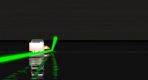
Yes the evaperation ducting can cause a huge number of optical problems. Even having multiple potential laser paths.
This can easily cause motion in every direction with a preferred direction due to wind movement. (think of the effect moving water can have). In the evaperation duct the humidity approaches 100% as you approach the water surface.
During the test. If possible
at each point record the temperature, at laser elevation and surface water temp. humidity, and wind speed and direction. Ideally the atmosphere chemical composition would also be useful. Oxygen, nitrogen, carbon dioxide %, etc is useful data for location refraction values.
The atmospheric pressure is also needed to fine tune calcs. This data can be used to further analyze your dataset.
Also include the technical datasheet for the equipment your using. (ie the laser.. ). The emitted wavelength etc is important...
In terms of beam dispersion, the evaperation duct can easily increase the beam radius. (extremely easy)
I would recommend on your backboard you have reference grid lines both horizontal and vertical. This way we remove the need to pixel count etc the beam radius from photos etc.
Remember the more data you provide, the greater your accuracy becomes. It also reflects diligents to important potential influences and steps to mitigate or acccount for their influence. For example if you sample the above list at each point. You can fine tune refraction data at each measurement point. ( physicists studying your paper, just love these details).
Of course they will also want to see your calculations. (To that end, I'm still putting together the list of formulas with correction formulas for locality).
Its quite intense...
Remember a good paper, will contain sufficient data, that doesn't require studying a photograph etc.
1) Appropriate formulas
2) accurate data, the more measurement data the better
3) A detailed list of possible measurement errors and the corrections. (including the related calculations that the corrections are effective)
4) good reference papers, including previous studies.
There is a rule of thumb, physicists usually only accept mathematical proof, that corrections are in place... They won't accept a verbal only description. Nor will they take anyones word that corrective measures are in place. Unless they can mathematically confirm the corrective measures...
For example an image isn't sufficient. What distortions are inherent to the image?
Just a side note, personally if I'm studying a paper proposing a new model and datasets. I personally won't accept any paper that doesn't include a detailed list or error margins on critical data points.
When you get down to it, most of your paper should detail possible errors, corrections and means to mathematically confirm those corrections. They will not accept anyones word on any aspect.
How can I measure the height of this ducting zone? Or to what humidity % level should I look for?
I have a concern how I can make accurate environmental measurements at each point. Do I have a fast way to determine the values quickly? The distance of 10kms takes about 1.5 hur in one way + the measurement stops - this might extend the timeframe very much. Is there a datalogger precise, all functions included and fast enough? Please advise
I'd like to collect more data too, you are right it makes the measurement more precise and understandable
"I would recommend on your backboard you have reference grid lines both horizontal and vertical."
This is correct, we'll do so
Agreed with all points 1 to 4
this is a very good idea - I haven't made now but important
"a detailed list or error margins on critical data points."0 -
Thanks again for the clarifications, Sandor.
It's good to know that you want to enhance the experiment, that's always a good practice.
Regarding the board, I wouldn't use a semi-transparent material anymore. This may be causing extra refraction and disrupting your data. I would suggest using an opaque material, taking the measures where the laser hits, and not on the other side. I would also strongly suggest you to not use any reflective material as a mean to capture the data. You want the light to be absorbed, not reflected. The reflective one is probably a good idea to help finding the beam, but not measuring it.
I agree with your point that 3.45m - 1m is also not looking good for the GE model, but I was intrigued by the "moving laser" effect you mentioned. If a laser can move up to 2m left and right, I think it's possible it may be also moving up and down by the same amount. A well collimated laser (lets say 40cm at 5km) may cause the top and bottom limits of the laser to be 2.4m off, and a not well collimated laser (let's say 2m at 5km) may cause the top and bottom limits to be up to 4m off. I had no idea that this NUDTZ effect, like you call it, could have such a big impact. Very interesting.
Only a quick correction, the beam center is always ~0 nm, not 1m.
. But anyway, you need to be 100% sure about what the beam size and beam dispersion are. From the pictures you sent, I was making a wild estimation of 2.05m at 5km, but it could easily be 40cm or 4m, there is no way to tell. The images, as you mentioned, are from too far away.My suggestions, some of them already mentioned in the thread:
- Put your laser higher than 1.25m. The refraction at this height is causing too much variation to the data.
- Use a different board material, preferably opaque.
- Definitely a higher board. Do you think you can make it at least 5m? Can you get a bigger boat so that bigger structures can be mounted there? 10m would be cool
- Validate the beam dispersion. Measure the top and bottom of the laser spot at 10m, 100m, 500m, 1km, 2km. After that, you go back and start the experiment. This is only a calibration round.
- Same water and air temperature
- Perpendicular board as it's easier to measure heights. If possible, pre-mark the heights there so that you don't need to measure it during the experiment.
- More measuring: Top and Bottom of the laser spots every 500m. This will give you 24 measurements every time you run the experiment.
- Don't switch measuring tools (from board to jacket).
I know it's too much to ask, but you have an uphill battle ahead of you.
I 'd like to make the curvature experiment perfect, that would probably take a few more attempts but I am very persistent in my works
Thanks for sharing the ideas to improve the measurements!
I am about to sign a cooperation agreement with the top geodezist and geophysics in Hungary and I will point them to this forum to review the suggested ideas.
"Regarding the board, I wouldn't use a semi-transparent material anymore."
"Regarding the board, I wouldn't use a semi-transparent material anymore.
I have only one concern: that the camera from the starting position is probably not going to be able to capture the beam on the boar all the way (we plan to do 10kms next time). In this case we can have a camera on the opposite shore, but that will not see the laser hit if the board is not transparent. We might as well use a camera in a boat that is following the measurement boat from the side.We will have a camera onboard facing the board to make the exact readings, but we can confirm the position only with timecode (that may not be well proved).
We have to check now in a test if an opal surface or a retroreflective surface (like a moviescreen) is better to capture the beam.
Please tell me your opinion on all this.
About the movement of the laser beam: it was noticed only at the measurements upto midnight.
The beam was moving ONLY sideways! It looked like someone was moving it on purpose, an unusually high horizontal vibration: quite high frequency and movement. I would like to attach a video here but I can't - can someone give me an idea how to?
What could be the purpose of the only sideway movement? (at this time the laser was at 50cms 4.1 feet)
We will definitely put the laser higher next time and use a big enough board to measure the beam. Bigger boat is not a problem, we can have powerboat, or a sailing boat with engine. The sail is a huge but not an ideal recording surface (in no wind conditions of course).
The beam dispersion can be automatically validated if the board is functioning well. The board would be the best indicator for refraction as well.
Water and air temperature measurements are quite hard to accomplish with the moving boat. I am not sure how we can make that accurate.
Perpendicular and measured board (the height of the board may be varied here to match the exact height from water surface - the exact height is still a question so it is 1.5 on the picture for now)
 1
1 -
The horizontal distance the boat travels is very clear in the video. Your white board is 2 meters wide so you can easily mark that width on the video and see the extents showing how far to the left and right the reflective patch and camera lens are showing reflections. You keep denying this is the case but that doesn't make the clear evidence go away.
You don't have to debate anything - the information is here for others to evaluate and review.I linked to the evidence showing the photographic analysis showing the 130cm mark is incorrect.The analysis was that the 1m tall board was ~452 pixels (which gives 452 pixels/meter).Total vertical height to the top of tape marked "1.3m" = 536 pixels.This is closer to ~1.186m than 1.3mSandor Szekely wrote: "On the photos you can tell the height of the laser by calculating the number of pixels above the board and comparing them with the board size. If you use a high resolution photoshop you can calculate quite precisely."Isn't that exactly what you did in all of your photos past about C8? Because you don't have a board even, you have a reflection off a special reflector on one guys coat and off the camera lens and that's it. But you called all of those slightly increasing heights by counting pixels - correct?This is exactly what Mick did and anyone can replicate it as he provided the details in his video.They also estimated that your board was slanted at ~24° and we see the people on the boat repeatedly putting the measuring tape along side the slanted board.This puts your measurements at ~1.3*cos(24°) off -- that's about .91 so that puts you at about 1.188 -- which agrees with the photographic analysis.So there are two data points that suggest this error is real.You can easily refute this -- please show the photo or place in the video where this tape is marked at 1.3m and it was done accurately with the tape measure fairly plumb and not slanted at ~24° along the board.it's that simple really. Maybe we just missed it.But continuing to assert that everything is perfect doesn't make your case. There is very good reason here to believe that this mark was placed incorrectly. That throws everything else about your calculations off.You also did not measure or demonstrate in any sufficient way the beam divergence past about C8 -- and you also have not accounted for the beam divergence in your calculations. Assertions do not make the data reliable.Again - your evidence is only needed if you want to convince others, or you can continue to ignore this -- it's really up to you.I gave the evidence supporting my argument, perhaps that could be addressed?I know that's painful to hear but these are absolutely critical and deep flaws in the methodology and measurements here. As I'm sure you are aware.=========== the rest of this is mostly irrelevant commentary on the aforementioned calculator ==================First of all, NOTHING about the refraction portion here was mentioned in the context of your experiment. I was showing another member that the calculator exists and is very handy and the results matched their numbers which gives us confidence in both. It simply uses a "surveyor standard refraction" as a GUIDE to what one would expect under fairly common conditions (see below).This, in no way, makes it a 'joke'. One must use information appropriately, as always.If by change you mean the medium contains components with different refractive indices then yes. But refraction doesn't require some kind of dynamic 'change' to make it happen. Everything could be entirely stable. In practice it isn't but that's a different store as to what refraction is "DUE to".It is just a tool -- you are free to go write your own refraction calculator. Mick & I have discussed our desire to do exactly that but it is an extremely complex and large project. 7/6*R is very easy and gives you a ballpark/starting point to consider. Perhaps it would be wiser to consider it since every surveyor knows that you must account for refraction when shooting longer sightlines.Note even remotely, it uses 7/6*R (see next bit)It's not really all that 'huge' -- on the horizon, for the Sun, the "average amount of atmospheric refraction" is given as ~34 arcminutes (slightly more than one apparent solar disc). That's going through the entire atmosphere the long way.
The calculator uses the approximation given by ATY based on a surveying rule of thumb:
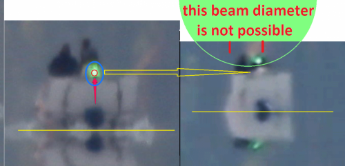
Please model the beam size on the boat clip. I explained that it is not possible to have 2 meter of the laser at the bottom of the beam, because that would make the beam like 10 meters diameter. Make a drawing that shows that the beam is 2 meters at the 1.8 meter height and it is not extending to the white board, and the beam center is at 3.4 meters.
This is not possible.
on the 118.5 cms / 132 cms debate I attached a video that was deleted from meta. Zack clearly explains the math with autocad: the beam should be at 3.19 meters (instead of the 4.32 meters)
That makes marginal difference in the outcome as the beam was recorded at 1.8 m - still a huge 1.4 m difference
here I lost all the huge sript I made so far so I have to rewrite it again. does this usually happen on the website? no saved copy

I attach here a picture: the first hit of the loop and the last direct hit of the loop.
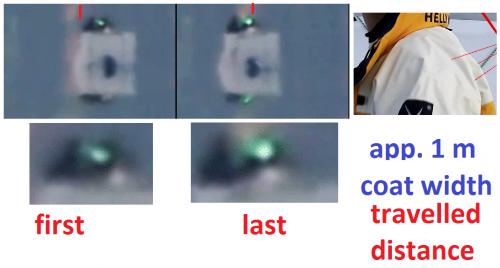
My question: if the beam was spread out to more meters as you suggest, how come that the beam is not seen on the retroreflective surface few inches below, but only in the camera lenses?
I have explained that NONE of the measurements were taken with the tape. At C1, C2 and C3 leveling process Dave used a tape to tell my laserist a number to calculate the increment of raising the laser. It has nothing to do with the measurements! Dave could as well say only "raise up".
We have explained in 2 video already that the photoshop measurements are inaccurate. I can not upload them here. Admin - any suggestions?
1st video: explaining the GE and FE calculated expected beam height. The 3.19 meters beam center is still not possible on the GE model.
2nd video: presenting on a real capture of a box why the picture can not be evaluated like Mick did.
Your calculation on the board height from angle is inaccurate.
"There is very good reason here to believe that this mark was placed incorrectly. That throws everything else about your calculations off."
So you believe in something that throws my calcualtion off...
" Assertions do not make the data reliable."
Please provide me your unrefutable datat that shows that my divergence was not as I said with the 0.08 mRad collimator. Unless you make a model of beam divergence that is coherent with the photo evidences, your claim is only an opinion. Check the above pictures and my concerns on your guess of beam divergence.
I see no evidences supporting your argument, you have not even modeled it if it possible.
Please refrain from comments like "I know that's painful to hear"
You are telling your opinion, do not make it look like you are the teacher here...
I lost a lot of script here on the explanation of the terresterial refraction.
so I conclude here:
You wrote: "But refraction doesn't require some kind of dynamic 'change' to make it happen. Everything could be entirely stable."
this is wrong, refraction is caused by CHANGE in the medium light travels through:
In a constant density, pressure , temperature medium there is no refraction - only retardation.
atmospheric refraction is a near constant value depending on the sun angles as sunlight coming from near vacuum and entering more dense, humid, and warmer air with more pressure and CO2
this should be - but not - taken into account when measureing the sun shadow lenght
terresterial refraction can not be calculated like this as local conditions effect the outcome very much. A local turbulance or a mirrage effect can never be calculated like this, so this calcualtor is wrong.
How come, that we make a good understandable definition of what we experience: the NUDTZ non uniform density transition zone - and it is criticized.
How come you suggest a calculator without any references to it's accuracy? I think this calculator is deceptive - I ask other people here not to take that into concideration.
Especially terresterial refraction is impossible to calculate like that on the many different aspects of modifying properties.
Standard refraction used in geodezical terrain measurements is 0.4 millimeter / kilometer. Dubble run leveling in 1999 by Swiss authors I have to look for that link)
"In order to obtain a hypothesis-free reduction of refraction influences, it is necessary to determine the refraction influences integrally along the propagation path. In the scope of this research work, the evaluation of the measured signal only is assumed to provide a satisfying estimation of the refraction influences. This estimation is based on image processing techniques which use the image data from built-in geodetic image sensors. Additionally, to estimate the refraction influences, the image processing techniques must be combined"
http://e-collection.library.ethz.ch/eserv/eth:23778/eth-23778-02.pdf
please read section 7 on the laser refraction experiment.
your comments on the avarage amount of refraction and the refraction calculator are wrong.
If the board was slanted at ~24° then No, you cannot "tell the height of the laser by calculating the number of pixels above the board and comparing them with the board size".
In any case, even with a vertical board* it is unsafe to measure on a photo. From my experience, every time there is a significant lack of precision.
*not even vertical, it should be perpendicular to the laser beam, and the photo taken from the origin of the laser beam, which is quite difficult (it should be installed like a rifle scope)
I agree with you that the pixel calculation is not an exact measurement. the best way is to mark all the sublines on the board too. In my measurements this gives some inaccuracy over long distance. in Mick's calculation it gives a greater difference.
I went back to Mike's calculator
https://www.metabunk.org/curve/?d=77&h=3&r=6371&u=m&a=n&fd=60&fp=3264
A small remark: (I did the same mistake)
The input distance should not be the straight line (the chord) but the length of the arc
I did the same mistake because in Autocad there is no way (at my knowledge) to draw an arc of a specific length. So I choose the facility and draw a straight line.
But the distances on Earth (as the length of the lake) are geodesics, they are not straight lines.
Of course AutoCad can calculate the lenght of an arc
Actually there may be an aspect to consider here. Over large bodies of water there is a specific type of Ducting.
Evaperation duct. I'm still looking into this but if I'm right your chosen height of the laser may have been too low...
Did you perchance recall the wind speed in knots? the evaperation duct height calculation requires that detail.
The back of envelope naval chart I'm looking at gives roughly 3 metres in height for the water temp/air temp in the video at zero knots.
Best time of day for sampling
when the temperature of the atmosphere most closely matches the surface temperature of the water. Reduces the potential evaperation duct height due to humidity gradient.
Bigger boat and higher height above water surface highly recommended to get to a more uniform elevation distribution. (with as little wind as possible)
Yes I think the ducting made some strange effects like the beam swinging sideways horizontally in our measurements from sunset to midnight as the laser was at 50cms (4.1 feet). This effect was not so much at the 4AM measurement this effect was reduced, no horizontal swinging of the laser beam.
We agree that the best timing is after sunrise when all temperature parameters are similar. We agree that raising the laser to higher position reduces this problem, we thought of raising the laser to 3 meters.
After sunset the water until the morning is very calm, low or no waves and low wind factor (on the 16th of Aug).
0 -
Physics is all about what you can mathematically define. In this case the thermodynamic state of this "self named region" requires a metric modelling. As well as the corresponding thermodynamic degrees of freedom of the system state being described.
Hence it is an undefined region, until you can properly define it
I wouldn't call myself an expert in atmospheric refraction. It's been awhile since I last practiced those particular equations.
To be 100% honest with you, I honestly feel learning how to calculate the best times yourself and show the refraction corrections on your paper is an important step in eliminating error margins.
I can certainly help explain how those equations work. (once you understand them, they can easily be programmed)
There are calcs available but if you don't understand how pressure density and temperature affects refraction and how to mathematically model such in an atmosphere they won't do much good.
Most calculators are typically designed with the basic formulas. They don't often have elevation corrections etc.
I'll post some metric examples when I get a chance. Takes a bit of time to post.
We did do approximation on the refraction at different times of the day that is how we came to the conclusion to do the experiments at night time and dawn. It is very hard to model (actually impossible) to model the terresterial refraction as it is due to change in small local conditions.
Like for example a turbulence is not possible to aviod if present.
We should try to define the best possible timing. As daytime has more changes in ambient conditions (more sunlight energy, wind factor) and we can see mirage only at daytime and laser is not well seen in daylight: I figured out that this is not the good time for the laser test.
Thank you for posting some examples so we can evaluate the data for the best possible timing of the measurement.
0 -
This image perfectly shows that the laser beam divergence is fairly large as you are clearly getting reflections over several meters wide as the boat slews across the view. These clips are found in the video starting at https://youtu.be/GBhDFO4NMrw?t=1111 (severalbroken clips from that point) and you can clearly see the boat is slewing very much side-to-side, it is not moving straight away from the laser, and you can see these glints across a very wide swath.
So all your showing is that a very divergent laser beam is hitting the reflective patch on the back of the white jacket and sometimes glinting off the camera lens pointing back at the dock.
These are not accurate measurement methodologies and do not indicate the center of the laser beam.
This, combined with the ~10cm error in your 'slope corrected leveling process' mean this experiment does not give us accurate results.
Here is my summary with l inks to the main metabunk posts that support them (credit to Mick for the analysis here, I'm just summarizing):
1) measuring height along the slanted board, likely resulting in ~9% error in 'slope corrected leveling' method [link1,link2] - confirmed by observing measuring methodology used and also by photo analysis. This likely resulted in a slight initial downward slope on the laser.
2) laser beam divergence is clearly much greater than they are admitting, creating false hits (shown in #3 & #5)
3) reflective patch on back of jacket and glints off camera lens giving false 'hits' [link1, link2]
4) 'direct hit in camera' is also demonstrated as not reliable (combined with #2 & #3) [link]
5) evidence that the laser is initially pointed slightly down (data at C5 & C8) [link]
If these are wrong please post the images that refute them. Here is kind of a guide as to what I think would be needed to address these points...
1) you would need images/video to show that the 130cm marking tape was placed accurately. We can see them using inaccurate methodology (slanted measurements) in other parts of the video but this isn't shown. So you can refute this by showing that the same methodology was not used when placing the 130cm tape mark but that it was made very plumb to the surface of the lake and not made by measuring the distance on the slanted board.
2) you would need to show the laser fully hitting the board at each point past ~C5 showing at least 1/2 extents of the beam divergence. All the evidence I can see past C4 is an increasingly divergent beam. Hits on the reflective tape and lens of the camera do not count to show that the laser divergence is small when we can plainly see in the video that this is not the case (something you seem to have a problem accepting).
3) the reflective patch and camera lens glints are pretty much self explanatory as being invalid. I don't see how you can show otherwise but I'm open to any further evidence presented.
4) 'direct hit on the camera' methodology is just busted - you can see the same effect in the camera even when the laser spot is small on the board in the closer measurements.
5) demonstrating #1 would call this into question depending on the results of that further analysis. But already at C8 we can see the beam is so diverged that it's difficult to see the actual extent of the beam hitting the board.
Do you have *anything* that shows the beam extents very clearly past C8 or not?
You might appreciate this calculator: https://www.metabunk.org/curve/?d=77&h=3&r=6371&u=m&a=n&fd=60&fp=3264
For 77km and an observer height of 3 meters it gives us the following:
Distance = 77 km (77000 m), View Height = 3 meters Radius = 6371 km (6371000 m)Horizon = 6.18 km (6182.72 m)Bulge = 116.33 metersDrop = 465.33 metersHidden= 393.57 metersWith Standard Refraction 7/6*r, radius = 7432.83 km (7432833.33 m)Refracted Horizon = 6.68 km (6678.1 m)Refracted Drop= 398.85 metersRefracted Hidden= 332.65 metersTilt Angle = 0.692 Degrees, (0.0121 Radians)Horizon Dip Angle = 0.056 Degrees, (0.0010 Radians)Most of these are pretty obvious and the full results explain some of the math used but very quickly...Horizon = distance from observer to horizon point (assuming no obstacles and level ground)Bulge = 116.33 meters -- that's the hump in the middle as you foundDrop = 465.33 meters -- the 'drop from a tangent line', as you foundHidden= 393.57 meters -- how much of an object at that distance the observer would be unable to see due to the Bulge blocking the view (again assuming everything is level and no obstacles)These all assume a Spherical Earth approximation but you can tweak the radius at your location if you want (but it only changes the results by micrometers for these smaller distances)Tilt angle is how much an object at that distance would be 'tilted' away from the observer (not very much)Horizon Dip Angle is more for higher elevations and over open waters, but gives the angle down to the horizon assuming no obstacles.Hello Darkstar
I don't agree with your assumption that the laser beam is spread out like 2 meters at that distance in the boat loop video.
The laser center height should be over 3 meters so therefore that slice of the circle - that is 2 meters wide - would suggest a huge laser beam like 10 meters. In this case we would see the laser hitting the board too, but it is not.
SO I think that the 1200mm optics is tricking us here.
WE have no error at the slope correction laser leveling. Mick was wrong and instead of admitting it he banned me from metabunk (for "trolling").
We proved in the autocad video that his 118.5 cms leveling theory will result a 3.19 meters beam height instead of the 3.45 meters (not a significant difference).
I answered to Mick's comments until I was not kicked from meta. I will not answer them again, as you copy pasted them here, PLS copy paste my answers too.
Thanks for sharing the meta calculator, but I am banned from meta. (reason: I am trolling... can someone explain me how I can be trolling on my own thread?)
so Mick case is closed, I am not debating with him. (unless he is here)
3) the reflective patch and camera lens glints are pretty much self explanatory as being invalid.
I don't see them invalid.
the refraction calculator is a joke...
refraction is DUE to CHANGE. so how can we estimate a "standard" constant change?
where can I put : time of the day, temperatures, humidity values and so on into that calculator?
what is the change here? only distance? this calculator was made to give the near same value as curvature. but this is not how terresterial refraction is calculated.
The sun is not where we see it, we see an apparent sun (exept when the sun is directly 90 degrees above us) - that is a huge atmospheric refraction. That is constant due to atmosphere conditions. But the terresterial refraction caused by local differences that curve light, it can not be calcualted with that calculator...
Well glad to see the approach to eliminate systematic errors. I've decided to pick up a couple of cheap lasers for myself lol.
I want to test my idea...
(curiosity killed the cat...)
Cool if you are trying your self too!
Please share your findings, and as well your difficulties with making such an experiment, like leveling with this accuracy.
I forgot to write that you can get pretty good collimators cheap for hand held lasers too, that is much more important than the power of the unit.
Lol a fixed mount of the additional lasers would help. Quite frankly the safety aspects should have been addressed in the first place....
Including anyone on the shoreline and other boaters
We have discussed the safety aspects of the laser with my laserist well ahead of the experiments. As this it was used as a 3W version it was safe to look into with the naked eye from over a kilometer distance. Actually we tried the sunglasses but at night time let's say it is impossible to wear in a boat.
A camera CCD is more sensitive to the laser beam but none of the cameras had any problem eighter.
We used green and blue dual lasers at the pre-test but we had collimator only for the green now. It would be good to use the blue to see the refraction (as the 2 colours have different refraction).
Our laserist and the Goldlaser company we work with is the biggest Hungarian outdoor laser show (and laser theater). They do events every week and well aware of the safety aspects.
Nudtz isn't a standard terminology. You won't find that terminology used in any textbooks. In point of detail the attempt to add it to Wiki has recently been placed on the deletion list.
http://deletedwikipedia.gawker-labs.com/wiki/N.U.D.T.Z.
I would just ignore this term as invalid
Particularly when the video states they sink into the NUDTZ ????
Either way there was far greater actual data presented on the other site to work with than was presented by the OP here. There is far too many systematic errors involved. The major issues posted by darkstar above.
We named the zone that we
non uniform density (that is the water vapour above the lake surface)
transition zone (meaning the zone - height above the surface)
I see this is the best explanation to what we experience.
why do you think it is invalid?
"far too many systematic errors" is not someting I can argue about, pls nem that you think is not accurate and pls define your point how much it effects our outcome.
I don't like this: Mick said this already at meta... first of all I can not see those posts, second the opposion claims should be explained here not referenced.
To explain my concern, on refractive index lets consider an example. The refractive index is typically highest the closer to the surface. Lets assign value N_1. At higher elevations temperature and pressure drop. Giving refractive index N_2.
Snells law [latex]\frac {sin\theta_1}{sin\theta_2}= \frac {N_2}{N_1}[/latex]
So as you increase elevation the ray will curve downward. This occurs regardless of the curvature of the Earth.
The humidity along the water surface will be higher than the ambient air. This gets into the potential of ducting...
The question is can we determine that the OP has the right conditions for sub-refraction? Which is possible but I don't see sub-refraction with the environment conditions mentioned in the OP..
Too bad the OP can't provide the proof that sub-refraction and not ducting is occurring. The quoted section occurs more readily over deserts with temperature inversion. Its a different situation with humidity of 71%.
[latex]N=77.6\frac{P}{T}+3.73*10^5\frac {e}{T^2}[/latex]
first term is dry air second term moist air. Key note the temperatures may invert but the pressure does not. In point of detail the moist air off the lake increases the pressure near the surface
That quoted section is just too convenient as "JUST THE RIGHT conditions to get the results I want...
I've been tinkering with the numbers all night. I can't find a combination that has a refractive curve upward from the Earths surface. Not within reasonable temperature variations. There is an extent in range of the signal due to reduced curvature but in all cases there is still a slight downward curve.
Anyone willing to show the calcs of upward refraction?
Mordred, please explain more about refraction conditions that could have occured at the experiment.
(or anyone who is expert in refraction)
This is an interesting thought " I can't find a combination that has a refractive curve upward from the Earths surface."
I assume that with inverted conditions from day to night the direction of refraction should change too. Of course there are many other factors to consider too. But this would really suprise me that refraction is always curving downwards.
Actually I am not sure if there is a possiblity to gather all ambient data - like we should measure the temp / hum factor all the way too.
So I think we should find at least the best possible timing of the experiment. We have to concider that a strong sunlight makes the laser invisible.
Please share advices on timing and weather conditions to look for in the upcoming experiment.
0 -
Sandor, in response to your post#92, my thoughts now are.
1) I am pleased if you wish to turn this into a proper scientific experiment.
2) Go to the university and find a proper surveyor. Buy her a cup of coffee (take her out to dinner?) and run my post#88 and the rest of these thoughts past her.
3) Send the laser back to the fairground and save the money.
4) Depending upon your budget hire a shore base tacheometer (Wild RDS etc) or a Total station.
5) Fix an outrigger pontoon on the boat and paint a large target at water level.
6) Sight on this target with your new equipment. It will give you sufficiently accurate horizontal distance and heighting over the ranges you are actually using.
7) Track the boat + pontoon on a series of traverses across the bay during daylight hours. This leaves the night for dancing etc.
8) Good luck in your mission, should you choose to accept it.
9) This post will self destruct in 9,000 years.
1. Thanks that is my intention!
2. Yeah I did find the beast possible geodezists and geophysisists to work with (not "she" but all "him"). I will name my partners after we have signed our cooperation agreement.
3. I love that laser and we are improving it. We will have a much finer increment adjusting of the beam and as well we will calibrate it in a longer distance.
4- We will surely use geodezy equipments in the next experiment with professional stuff.
5.-7. I am thankfull if you write your ideas of the proper or best possible method of making the measurements. We will model and make real test of the best ones.
8. Thank you again! I am commited to find the truth.
9. Time is an illusion
(think about the one hour you spend at the dentist - or your loved ones)
Yes it is complicated.
But if you replace the bulge with a wall 70 cm high exactly in the middle, it gives the same effect.
Which makes me think that from 1.50 height, even the shore is visible. 1.40m is the limit.
From 1.25m, it must be calculated.
Bizarre. That would make the beam go left & right, not only up & down.
I am answering in time order (to the comments I can) but this comment caught my eye.
"Bizarre. That would make the beam go left & right, "
that is exactly what happened in our 2nd experiment! It was before midnight, and the beam was like waving left to right in a very noticable amount viewing from the boat. I even called the laserist on the shore if they are moving the laser? she said of course not the laser is not touched.
The effect was exactly as you described it - a huge (like 10 meters) swing looking at the beam from the boat.
We saw this effect at the midnight measurement only.
Yes, I would also say : "bizarre"
Thanks for the reply, Sandor.
I checked your online folder. In C2.jpg and C3.jpg you can see almost the whole circumference of the beam spot. I would estimate the diameter at around 20cm, maybe 30 cm at least as the top of the spot is not visible. That would mean a 20 cm minimum spread at 400m to 600m distance. Please let me know if I am wrong here as this is the basis for my whole analysis
Image below is C2.jpg for reference.
https://drive.google.com/file/d/0B2gyF12ygRBjZUhnMWRPZXhza2M/view?usp=sharing
With a 0.08 mRad collimator, the expected diameter should be around 7cm to 8cm at 400m (I am estimating a 4cm initial beam size, again, let me know if I am wrong), but I can see it's a little bigger than that. I think the refraction is disrupting your beam a lot, or maybe the laser was not well calibrated.
In the C18.jpg image you attached, the beam is not hitting the white board anymore, so we need to work with math only. With a 0.08mRad, at 5.038m distance, the spot diameter would be around 44cm. But at 400m, it looked like the spot was already at 20cm, so at 5km distance I would estimate it to be 205cm, or 2.05m. It's consistent with the animated gif you posted, as we can see the beam hitting the reflective jacket several times as the boat moves horizontally. The laser could be hitting the jacket anywhere in the 2m spot I think.
With all that said, I am happy that you are planning to get a 0.003mRad collimated laser in the second experiment, but you need to make sure that it's well calibrated, as the 0.08 mRad you used in this first experiment was not doing well. Or if the disruption was caused by refraction only, this also needs to be taken care of.
Well let's start with the board. It is plastic with 0.5 cm inner square tubing (sold in Praktiker garden shops)
I am not sure this is a good solution for the board as it leads the lights internally well so the beam looks bigger.
Next time I would use a normal plastic sheet or a retroreflective material - not sure what would be the best.
Our opinion is that the beam was not spreading out very much over the long distance.
Here I attach my comparison on the beam divergence at 2 distances.
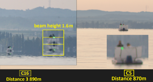
Fine calibration of the laser beam can be an issue, next time we do it on longer distance. (it was now calibrated on about 100 meters distance)
"With a 0.08mRad, at 5.038m distance, the spot diameter would be around 44cm."
this could be realistic in my opinion.
"But at 400m, it looked like the spot was already at 20cm, so at 5km distance I would estimate it to be 205cm, or 2.05m."
Then the beam center would be about 1 meter (radius) so the beam should be visible at a height of minimum 2.45 meters (3.45 - 1).
The beam was recorded at 1.7 meters so it is still a big difference (0.75 meter).
I think our beam was well collimated. The motion gif picture is a high speed very distorted image (1200mm optics) that shows the reflexion in the camera lens when we are pointing it directly into the laser.
here I attach the corresponding dat, C18 at the last row:
Balaton-laser-exp-816-data-sheet-4th-measurement final.pdf
0 -
Thank you again, Boxer for the partial explanation.
But still why present the data as a histogram?
If we regard this as a statistical sampling of the surface water then it seems to point to the Wiki number of 105 being the mean of the histogram.
But this information is useless without knowing what part of the water surface was sampled.
All the flight paths were along the edge.
Like the rest of the information provided it requires a proper method statement and declaration of variables to accompany it to make any true sense of it.
Further none of this alters the possibility of local flatness of the geoid and ground surface (ie the lake bed) supporting a flat water surface since the geoid 'corrections' are not shown.
Studiot
"All the flight paths were along the edge."
Correct, this was confirmed by the leader of the LIDAR experiment today. I will get soon the flight path measurement data on the exact same route as our boat measurement. I will share for review.
I fully agree with everything else you wrote here.
0 -
It would appear that the OP is indeed another attempt to push the misguided flat earth dogma.
However instead of ridicule or minor arguments against his results we should all consider this.
Sandor's results, if the survey was properly conducted, will be correct.
The water surface departs from following the Earth's curvature; it is essentially flat.
Note my question in post#6 that has gone unanswered
Lake Balaton is an important lake because of its size and topography.
Only 12 metres deep at max and much less on average as my early question shows there is a basic issue with surveying the water/air surface.
[aside]Although I have not been there since 1956 and at that time I was too young to be interested in geomorphological history, my daughter had a wonderful holiday there earlier this year.
I can definitely recommend it, it is one of Europe's Geopark sites.[/aside]
As such it has attracted much august study about its formation which reveals the clue to the conundrum.
Lake Balaton is a rift lake.
That is it lies in the bottom of a rift valley.
Rift valleys, such as the African and Red Sea rifts, are noted for their flat bottoms, which can run for great distances.
Rifts are no great respectors of the Earth's curvature.
So the underlying topography is, well, flat.
And a very shallow lake has formed with sediment deposits on the rift valley floor giving a slight slope to the bottom.
But since the average depth is only about 3 m
How can the water surface not be as flat as the ground on which it is resting?
This is not support for the flat earth view, just modern science sorting the fact from the fiction and properly acknowledging real facts.
Here is a sketch geo history of the rift.
Dear Stuiot and the other members
I am sorry I have not been here for a day, I will catch up now with the comments and answer them.
I am researching the GE vs FE theory since years now but here I would like to focus on the lake curvature experiment in the thread.
"Sandor's results, if the survey was properly conducted, will be correct. The water surface departs from following the Earth's curvature; it is essentially flat."
our 16th of august experiment was the first measurement we have done so far with the laser so it has some things to reconsider and make better in the upcoming measurements. We will work toghether with a Hungarian university on the study so the results will be more precise and definite too.
Studiot, I have learned about the bottom of the lake from your information here!
Sorry, for your question at post #6 I have to gather information from the university as well.
"How can the water surface not be as flat as the ground on which it is resting?
This is not support for the flat earth view, just modern science sorting the fact from the fiction and properly acknowledging real facts."
This shall be our motto for the thread! Exactly right question
I can notice from your video in Youtube that your measuring white board is around 1.35m high.
How did you take your measures starting in row 15 in your table as those are all higher than 1.35m? After 12min in your video the laser is not hitting the white board anymore ...
I also noticed the beam diameter in the white board getting bigger and bigger. At around 14min the circle is nice and small. At around 19:10, the circle is barely recognizable. How did this "spread" impact your measures? How did you estimate the correct beam height as it was not nice and small anymore?
Great structure you put there by the way.
Hello Mr Marker
I have uploaded all the measurement evaluation pictures here:
https://drive.google.com/drive/folders/0B2gyF12ygRBjU0NSSmIxbXU4bVk
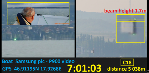
so you can check them individually and see how I marked the laser hits.
We had laser direct hits on the reflective jacket and as well in the camera optics too.
The collimator on the laser beam is 0.08 mRad in our measurements.
Good point, +1
Variation of spot size is an important point when finding the centre of a laser beam.
Are you aware that a collimation error of 0.001 degrees corresponds to 1.3 metres at 77km range?
By the way, .001 degrees is nearly 4 seconds of arc and pretty poor accuracy for this sort of work.
Standard geodetic work at this range would be at least two orders of magnitude finer and really accurate work better still.
Studiot, please note:
our collimator was 0.08 mRad this time (on the longest range measurement it will be probably 0.003 mRad)
and I say we need an accuracy of 0.001 degrees for laser leveling.
0
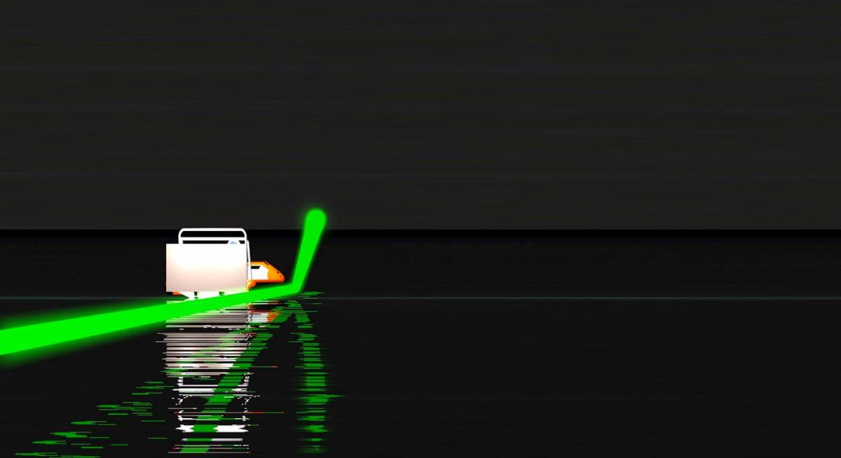
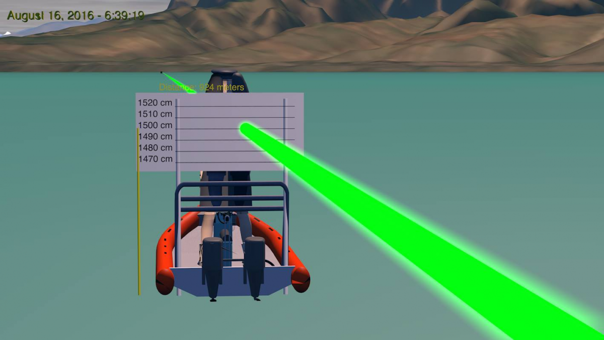
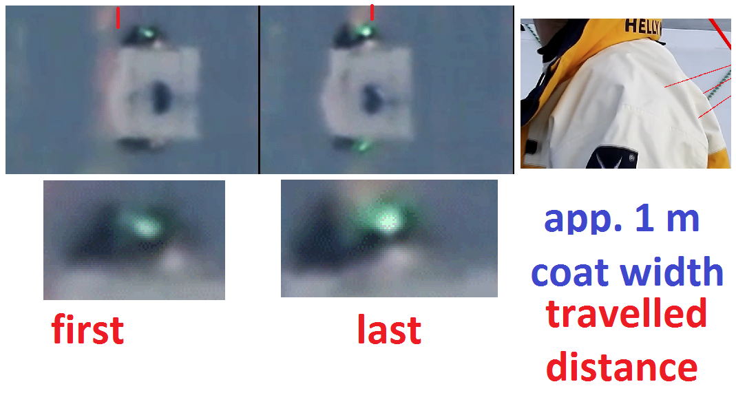


Laser curvature test on lake Balaton
in Speculations
Posted
Dear all!
I have made the presentation to the Hungarian Geological and Geodezical Institute, and we have aggreed to make a cooperation on the upcoming Balaton lake and over land laser curvature measurements!
We are now applying for director approval and then setup the first measurement on the lake.
https://www.mfgi.hu/en/node/456
We will show our plan for the experiment after it has been properly designed and animated so we can discuss the hints and tipps before the measurement is done.
1) This should start with a standard aims and objectives statement.
The aim of the experiment is to measure the curvature of water surface at the lake Balaton.
2) Then provide an estimate of the expected range of measurement values and accuracies required so suitable equipment and experimental methods can be devised.
We are aiming to take measurements from 10km up to 77kms on the lake surface. Detailed description will include all measurement calculations and experimental methods.
3) Offer a system of control or reference points, established to a higher standard than the survey itself and preferably established by a different method, independent of the survey measurement technique.
We are aiming to fixed objects on shore in different heights as planned.
4) Provide a proper method statement for the survey itself.
This is not yet ready.
I'd like to add one comment to the lake: the Balaton does not have an all time functional outflow, because it is blocked and opened only once in a few years.