


MMK
-
Posts
39 -
Joined
-
Last visited
Content Type
Profiles
Forums
Events
Posts posted by MMK
-
-
I have been able to calculate orientations using Pololu MiniIMU-9DOF v2 (interfaced with Arduino UNO R3); essentially an AHRS using code found at Github! Now out of curiosity i want to replicate this 3D track as witnessed in this video as below:-
http://www.youtube.com/watch?v=6ijArKE8vKU
How do I proceed?? what I know is that he used MATLAB for plotting data.......... Plz help!
0 -
"I have some metal parts of a combustion chamber we fabricated for our Gas Turbine Engine....... Now I want them to be ceramic coated!!"
Why?
Unless you can do plasma spraying or something, any sort of enamel will need to be baked on above it's melting point so that melting point will have to be less than that of the steel (or whatever) that the blade is made from.
That means that the coated blade will be less heat resistant then the uncoated one.
It will also weigh more.
It's likely that it will have a less accurately defined shape.
What are you seeking to achieve with a ceramic coating?
In any event,. if you do decide to use one, make sure it has the same thermal expansion coefficient as the metal you are coating.
With Ceramic Coatings I want to achieve higher temperature resistance for the metal parts...... not just these but for the nozzle sections too. Well i havent studied materials yet but they are in my course of studies in the next semester that is why I asked for help! Its my mini-project........!
0 -
But It doesnt answer my question regarding how am I gonna use Ceramic Slurry for coating purposes??? Also if I go for Porcelein Enamel is it a good option? If it is how should I proceed???
0 -
I have some metal parts of a combustion chamber we fabricated for our Gas Turbine Engine....... Now I want them to be ceramic coated!! How am I gonna do that??? Plz recommend easier ways for the same considering the fact that the equipment around here is not of very high standards!! And also how do I coat the same with ceramic slurry if i get my hands on it!!!!
 Help me on it!!!0
 -
I have an Arduino UNO R3...... I actually wants to interface it with a 6DOF IMU so that I can get visual data on my computer from it........ I am a novice on programming the Microcontroller so plzz provide me source codes and useful links for the same! Also recommend me a good IMU too!
>>A code I found on the internet:-#define Gyro_Sens 0.00333 // Gyro sensitivity = 3.33mV/deg/s
#define VPQ 0.00322581 // Volts Per Quid --- value of 3.3V/1023
#define ADC_Avg_Num 100.// Number of averaging readings for calibration
#define Rad2Deg 57.2957795 // 1 radian = 57.2957795 degrees
#define Deg2Rad 0.0174532925 // 0.0174532925 rads = 1 deg
//The minimum and maximum values that came from
//the accelerometer...
//You very well may need to change these
int minValx = 403;
int maxValx = 610;
int minValy = 401;
int maxValy = 614;
int minValz = 413;
int maxValz = 619;
//Calibration variables
float Gx_Cal, Gy_Cal, Gz_Cal;
float GyroRateX=0, GyroRateY=0, GyroAngleZ=0, GyroAngleZ_dt=0;
float AccAngleX=0, AccAngleY=0, AccAngleZ=0;
float Pitch, Yaw, Roll;
int AN[6]; // Hold analogRead data
unsigned long pre_time, print_clock=0;
float dtime;
void setup()
{
analogReference(EXTERNAL); // sets reference voltage to use voltage applied to VREF pin
Serial.begin(115200);
delay(300); // Give things time to "warm-up"
Calibrate(); // Calibrate sensors
pre_time = millis(); //store current time to be used as "previous" time
}
void loop()
{
if(millis()-pre_time>=20) // Read ADC and does Calculations every 20ms
{
dtime=millis()-pre_time; //current time - previous time
pre_time = millis(); //store current time to be used as "previous" time
dtime=dtime/1000.;
Read_ADC();
Calculate();
}
if(millis()-print_clock>=50) //print every 50ms
{
Serial.print(Pitch);
Serial.print(",");
Serial.print(Roll);
Serial.print(",");
Serial.println(Yaw);
print_clock=millis(); // store current time
} //end if
}
///////////////////////////////////////////////////////////////////////
//////////////////////// Functions ///////////////////////////////
///////////////////////////////////////////////////////////////////////
void Read_ADC(void)
{
AN[0] = analogRead(1); // Gyro_X
AN[1] = analogRead(0); // Gyro_Y
AN[2] = analogRead(2); // Gyro_Z
AN[3] = analogRead(5); // Acc_X
AN[4] = analogRead(4); // Acc_Y
AN[5] = analogRead(3); // Acc_Z
}
void Calculate(void)
{
// Gyro portion
//----------------------------------------------------------------
GyroRateX = -1.0*dtime * (((AN[0]*3.3)/1023.-Gx_Cal)/Gyro_Sens);
GyroRateY = dtime * (((AN[1]*3.3)/1023.-Gy_Cal)/Gyro_Sens);
GyroAngleZ_dt = dtime * (((AN[2]*3.3)/1023.-Gz_Cal)/Gyro_Sens);
GyroAngleZ += -1.0 * GyroAngleZ_dt * (1/(cos(Deg2Rad*Roll))); // convert Roll angle to Rads, find sin to use as scaler for Yaw
if(GyroAngleZ<0) GyroAngleZ+=360; // Keep within range of 0-360 deg
if(GyroAngleZ>=360) GyroAngleZ-=360;
//----------------------------------------------------------------
//convert read values to degrees -90 to 90 - Needed for atan2
int xAng = map(AN[3], minValx, maxValx, -90, 90);
int yAng = map(AN[4], minValy, maxValy, -90, 90);
int zAng = map(AN[5], minValz, maxValz, -90, 90);
//Caculate 360deg values like so: atan2(-yAng, -zAng)
//atan2 outputs the value of -π to π (radians)
//We are then converting the radians to degrees
AccAngleX = Rad2Deg * (atan2(-xAng, -zAng) + PI);
AccAngleY = Rad2Deg * (atan2(-yAng, -zAng) + PI);
// Keep angles between +-180deg
if(AccAngleX>180) AccAngleX=AccAngleX-360;
if(AccAngleY<=180) AccAngleY=-1.0*AccAngleY;
if(AccAngleY>180) AccAngleY=360-AccAngleY;
// Final values...
Roll = (0.98)*(Roll + GyroRateX) + (0.02)*(AccAngleX);
Pitch = (0.98)*(Pitch + GyroRateY) + (0.02)*(AccAngleY);
Yaw = GyroAngleZ;
}
// Reads and averages ADC values for calibration
float Avg_ADC(int ADC_In)
{
long ADC_Temp=0;
for(int i=0; i<ADC_Avg_Num; i++)
{
ADC_Temp = ADC_Temp+analogRead(ADC_In);
delay(10); // Delay 10ms due to gyro bandwidth limit of 140Hz (~7.1ms)
}
return VPQ*(ADC_Temp/ADC_Avg_Num); //Average ADC, convert to volts
}
void Calibrate(void)
{
Gx_Cal = Avg_ADC(1); // Gyro_x on pin 1
Gy_Cal = Avg_ADC(0); // Gyro_y on pin 0
Gz_Cal = Avg_ADC(2); // Gyro_z on pin 2
}
////////////////////////
//////// END CODE //////
////////////////////////I found this code from a website....... Will it work if I use it in the below configuration????? And for visualization I use this Altitude Indicator below:-Plz tell me if all of this stuff will work out......... and if not plz help me in making changes here....... PLZ HELP!!!0
 -
I know it sounds like too much but Is there a way I can get live feed of my RC CAR location on my laptop in a google-maps format??? I have seen a build in which they interfaced their GPS module with an 8051 Microcontroller which actually showed the altitude and latitudes of its location on an LCD! Plz Help!!!
0 -
yup! it was! Changed the transistor and it worked like a charm!
 0
0 -
Thanks everyone....... my circuit is now working fine and its producing sparks too! Thanks for every ones help!!!!!!
0 -
You did not answer if the LED still blinks from pin 3 when the halogen or coil is connected, does it?
What lamp did you use to check Step 2? Voltage and effect? The LED, instrument light 1-2 watt, taillight 10-25 watt or other?
Is the 1N4004 diode mounted in the correct direction? The side with the grey line on it should be connected between TR1 and the 100 ohm resistor, while the other side without the line should go to the ground.

If 1N4004 is turned upside down then the TR2 will be choked to only drain ~350 milliamperes or less through the coil/halogen.
It could also be that the power transistors was not meant to drive such a large load in this setting, the 100 ohm resistor determines how much TR2 will open up and it could have a to high value for a 4-5 ampere load, likewise the 5.6k ohm resitor might have a to high value to fully open TR1 and give the 100 ohm resistor the current it needs to open TR2.
Don't have more time right now but we can dive deeper into this later if needed.
Sir I dont know how it happened but my TR1 transistor i.e., C559 is faulty! It was alright when I connected it in the first place! I will buy a new one tomorrow probably and will do further tests and inform u about it! And Sir the answer is no for whether the LED blinks when the circuit is connected to the Coil! And Sir I am using 1N4007 diode in place of 1N4004...... b/c I have plenty of them!
0 -
Did you test Step 3? A light bulb from the headlights of a car should be large enough.
Does the LED continue to blink at pin 3 when the coil or a large light bulb is connected?
Does the LED blink when connected to the cross point between TR1, 1N4004 and 100 ohm resistor? With and without the coil?
(LED in series with the 1k resistor.)
Does the LED blink when connected from coil+ to coil-, with and without the coil?
(LED in series with the 1k resistor.)
Does the spark plug have a common grounding with the ignition coil so the secondary circuit is closed when a spark jumps?
(Watch out, high voltage in the range of 10 000 to 40 000 volts from the ignition coil's secondary winding when working.)
No Sir Step # 3 is a failure! I couldn't light up my halogen lamp........ also that when i connect the LED at the coil terminals with Coil mounted it doesnt blink a bit! not even it lights up!
And without the coil......... LED fails to light up when connected at TR1 or Diode or 100 ohm resistor w.r.t ground!!!!
What should i do now sir???
 0
0 -
I found out that my capacitor at pin 5 was short...... so I just removed it! Now this done I again connected LED at Pin 3 and yes it blinked rapidly!!!! Now Step 1 as well as step 2 stands verified!!! yupeeeee

But when I connected my ignition coil to it now, it didnt produced any spark!!! What might be the reason for this???
0 -
That is unusual. It has worked for me fime testing ignition coils, several times, jumping a spark across the spark plug. What is the measured AC voltage on the primary while energized ?
Plan B : Get an automotive relay and connect its common and normally closed contacts in series to your 12V DC battery source. It will provide a faster turn-off. Let me see if I find a schematic for your better understanding...
+12V--------------C---/ .----NC------------coil primary-------------GND
NC------------relay coil----------------GND
In other words, both coils in parallel betwee the NC contact of the relay and battery minus. But remember the spark plug thread must be connected to the secondary or common, whatever your coil has.
Here is something :
http://www.popsci.com/diy/article/2009-12/shocking-truth-how-make-high-voltage-sparks
Come back with results.
If you cannot make it work and short on time... try a gas stove spark module, available from most discarded ones or at the appliance parts store.
at primary it was 12 VAC and i am getting 220 VAC at my wall socket @ 50Hz frequency!
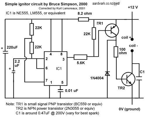
I don't think those resistors are the problem, they determine the timing of the pulses and unless a change from 10 Hz to 8 Hz is crucial, then the circuit should work.

In the astable mode, the frequency of the pulse stream depends on the values of R1, R2 and C:

The high time from each pulse is given by:

and the low time from each pulse is given by:

where R1 and R2 are the values of the resistors in ohms and C is the value of the capacitor in farads.
http://en.wikipedia.org/wiki/555_timer_IC#Astable
With R1=22k R2=22k and C=2.2µ the Output at pin 3 is High for 0.067 seconds and Low for 0.034 seconds -> frequency = 9.9 Hz.
With R1=27k R2=27k and C=2.2µ the Output at pin 3 is High for 0.082 seconds and Low for 0.041 seconds -> frequency = 8.1 Hz.
Step 1 is to determine if the output at pin 3 is pulsing or not, this can be done with an oscilloscope or by temporarily unconnect the 5.6k resistor and instead connect a very small 12 VDC light bulb no more than 2 Watts, or a LED in series with a 1k resistor between pin 3 and ground. It should blink around 8 to 10 times each second.
If step 1 is OK then the 555 circuit is working properly.
Step 2 is to connect a small 12VDC light bulb where the ignition coil is ment to be, it should flash rapidly.
If step 2 is OK the power transistors are working properly.
Step 3 is to connect a large 12VDC light bulb where the ignition coil is ment to be, it should flash rapidly.
(With large I mean that it needs to drain an equal amount of current as the coil does.)
If step 3 is OK then the problem is with the coil or spark plug.
EDIT: Changed the typo "pin 2" to the correct "pin 3" in Step 1.
Sir Step # 01 failed!!!! My LED failed to blink not even a single time....... but when I connect it to pin 4 or even 8 it lights up continuously......... but no blinking at Pin # 03!!!!!!! NOT EVEN ONCE! What should I do now???
0 -
Umm Sir isnt it should be pin 3 rather than pin 2? plz tell me.........
0 -
Hello MMK, my experience with 12 V coils tells me your coil requires a saturation, a quick drop in voltage that produces the spike in secondary voltage. An old system had a set of points that opened to initiate the coil collapse, the condenser eliminates the voltage arc that would jump the open points. Yours is electronic but is the same in principle. Does your coil have an internal capacitor? Is your coils capacitor tuned to that coil? Those two have to oscillate together to produce inductance in the secondary side. Have you ohm tested the coil? Both secondary and primary. Some coils need the braket to be grounded to work, others use the neg. for both primary and secondary. arc
Yeah I have ohm tested this coil and i know its perfectly okay!
I think this circuit might not be working for me because i might not have used the correct resistors Pin 7 and 2, 6! I used 27k ohm ones in place of 22k ohm!!! What do u all think?? is it might be the problem???
Transformers run on alternating current. That ignition coil is a transformer. What you heard does not matter. Nothing to elaborate; D O I T !
Sir I followed your advice but it didnt worked!! What should I do now???
 i am already short on time and this thungy has taken a toll on me!!!! plz helpppppppppppppp!0
 -
Okay I will do it today!
If anything happens I will surely hit u okie! 
Transformers run on alternating current. That ignition coil is a transformer. What you heard does not matter. Nothing to elaborate; D O I T !
Btw will it work with just any step down transformer...... whose output is at 12VAC?
0 -
Ok, so you need to disconnect both the coil and the resistor to get that voltage? Or is it enough to just disconnect the coil? Sounds a bit like the coil might be the problem then.
It takes both the Resistor and Coil to be disconnected to get the above stated readings!
MMK:
The coil 'metal body' for that Suzuki one is still its non-insulated metal body iron core, as the bracket seems insulated on rubber mounts, or one of the primary terminals is also common with the secondary. It has to connect to the spark plug thread.
To see pulses on pin 3 you need to use an oscilloscope. A DC volt meter will not tell such, will show high or low depending on the oscillator status, or somewhere in between for AC scale, which may kind of detect/read the oscillation.
If the contraption is not going to operate in a vehicle, you do not need to make it work with a 12 Volt battery nor the oscillator circuitry.
Pick a 'wall wart' 120VAC to 12VAC transformer and connect your coil primary to it, nothing else. Watch were you put your fingers or you may get the jiggles.
Sir are u proposing to run an ignition coil with stepped- down Alternating Current? I heard that an ignition coil works on pulsed DC! plz elaborate on it! Thanks!
0 -
Well, if you were to take the ignition circuit, and redesign it so it is simpler, you got to look at what you want it to do, and in this case, you want it to ignite the engine. So, you need to hook it up to your car lighter. then, you need to push it in and watch the sparks - the power used in the lighter will easily light the engine, yes?
Or, you could hook the key up so that it carries a charge. when you twist it, it could have a 'battery' and send a shock to the engine. don't connect the circuit, simply make the key go between the circuit to connect it, and off you go.
Umm Sorry but I dont intend to use it in a car..........
! I am a Mechanical Engineering Student and am designing a Micro Gas Turbine......... Wanna use this on that! 
No! The Ignition Coil is not metal body bottle shaped one......... Its a standard Suzuki Cultus Coil!

@pwagen:-
When the Coil was connected with my circuit I didnt get ant potential difference w.r.t ground at pin 3...... but pin 4 and pin 8 shows 12 Volts! All I get is around 2 Volts at the base of transistor BC559 that is after 5.6Kohm resistor at pin 3! Even if I disconnect the whole Pin 3 with the 5.6K ohm resistor I am getting No output at Pin3..........
I am using a Multimeter to check for voltages!
But when I disconnected this Ignition Coil from my circuit....... the Pin 3 showed a potential difference of around 11.86 V! Pin 8 and 4 showed 12.26 Volts!.......
This 11.86V reading appears only when the 5.6K ohm resistor is disconnected from pin 3 of 555 IC!
0 -
Umm do u think my IC has burned or something? plz help its urgent!!!!
0 -
No! The Ignition Coil is not metal body bottle shaped one......... Its a standard Suzuki Cultus Coil!
@pwagen:-
When the Coil was connected with my circuit I didnt get ant potential difference w.r.t ground at pin 3...... but pin 4 and pin 8 shows 12 Volts! All I get is around 2 Volts at the base of transistor BC559 that is after 5.6Kohm resistor at pin 3! Even if I disconnect the whole Pin 3 with the 5.6K ohm resistor I am getting No output at Pin3..........
I am using a Multimeter to check for voltages!
But when I disconnected this Ignition Coil from my circuit....... the Pin 3 showed a potential difference of around 11.86 V! Pin 8 and 4 showed 12.26 Volts!.......
0 -
I followed this circuit diagram for making my ignition Circuit and connected it to an ignition coil of a car but it does not produce any spark at the spark plug?? Where do I get it wrong??? Also I didnt had 3 in qty 22000 ohm resistors that is why i used 27000 ohm resistors in place of the two resistors connected at pin 2 of NE555 IC! the other 22000 ohm resistor is correct!
Also I am using a 12V 80 Amps Car battery for powering this circuit!
Plz help me on this!!!!

 0
0 -
I have RXTX-433M RF modules........ in order to increase the range b/w the Transmitter & Receiver to communicate........ I plan to make a amplifier......... can a class A amplifier hooked on before the antenna section on Transmitter module will work???? or Class C???? plz give me a good circuit diagram too as I couldnt find one on google! Plz HELP ME!!!!! Remember that the Transmitter & Receiver is used for activating relays and not for any audio signals! i just wanna increase the RANGE of this system!!
0 -
Mod I havent seen a single post which will help us in solving this question.........
 0
0 -
Q:- The resistances of commercially-available discrete resistors are restricted to particular sets. For example, the available values of resistors with 10% tolerance are selections from the E12 set multiplied by a power of ten from 100 through 105. The E12 set is:
E12={10,12,15,18,22,27,33,39,47,56,68,82…}
Thus, you can buy 10% resistors with a nominal resistance of 330Ω or 33kΩ, but not 350Ω. Furthermore, the "tolerance" means that if you buy a 10% 390Ω resistor you can be sure that its resistance is between 351Ω and 429Ω.
In this problem we need to choose 10% resistors to make a current divider that meets a given specification.Image (Circuit Diagram) could be found out at: http://tinyurl.com/d7yv99y
We are given an input current Iin=100μA and a linear resistive load represented by the resistor RL . Our resistive load is not regulated for the high current provided by our current source, so we add a resistor RS in parallel to divide the current such that IL≈40μA. An additional requirement is that the Thevenin resistance as seen from the load terminals is between 60kΩ and 80kΩ. Assume first that the resistors have their nominal resistance. Come up with resistors RS and RL such that the divider ratio IL/Iin is within 10% of the requirement.
Of course, the resistances you chose are just nominal. Given that they are only guaranteed to have resistances within 10% of the nominal value, what is the largest and smallest value that VL may have?
Find: Rs, RL, VL(max) and VL (min)........0 -
What if I apply an electric arc on black powder........ will ignite it???
0
Pulse Jet
in Amateur Science
Posted
I was planning on building a 25lbs Valved Pulse Jet Engine but couldnt figure out how much thick should the tail pipe and the combustion chamber be? Can I use a #25 Gague Mild Steel Sheet rolled out for my given diameter for the same purposes? Will it be enough?? Plz help!