Enthalpy
-
Posts
3887 -
Joined
-
Last visited
-
Days Won
1
Content Type
Profiles
Forums
Events
Everything posted by Enthalpy
-
As a student or young engineer, I used to answer "impossible", for instance about Reagan's directed energy weapons. Meanwhile these weapons exist, and as my beard is white now, I say instead "I don't see how" or "Seems difficult to me". An aircraft carrier or a battleship aren't quite agile. The 700km range (just a natural figure from a single stage with safe smokeless powder) is covered in 4min. This gives a battleship time to change its course (an aircraft carrier has other constraints), not to flee far away. It has time to steer 90° away, and at 20m/s, be 5km away from the targeted location. An expensive impactor would try to follow the movement. This needs much fuel, as the impactor must follow the target's acceleration. Or a salvo of cheap impactors can rely on chance. One truck can launch 20+ missiles, 20 trucks can fire simultaneously, and each missile can release 20 impactors, totalling 8 000 impactors. Against an aeronaval group of ten 150m*20m ships, impacts spread on R=5km hit 12 times as a mean. Even a single carrier or battleship is probably hit twice. The salvo method is low-tech, far below what Iran or North Korea already achieve, and it is much cheaper than both the targets and the protective means. Among the static targets are nuclear power plants. No affordable shield stops such an impactor. Countries with reactors everywhere, like France or Japan, would get uninhabitable by the mere released radioactivity. If you think at what an impact does at the core's side of a fast neutrons reactor (and possibly an epithermal neutrons reactor too), it's terrifying. Angela Merkel (PhD for nuclear physics) closed all fast neutrons reactors in Germany after I suggested this on the web. I've heard about three trials. A 747-borne laser destroys a missile starting 500km away. A combat ship turret (an F-35 maybe too) destroys a drone few km away. A truck destroys Hamas-styled rockets few km away. These targets were soft, with thin casings absorbing light and fragile to heat. A kinetic impacts is a solid piece of metal - the design can keep the rocket engine's casing or not. The available time is similar, in the 1mn range if the defender notices the missile start and can act at long range. The number of incoming impactors makes a difference. From a salvo of 8 000 impactors, you want to destroy many more than the 12 in the previous evaluation, but one present laser can't destroy many impactors successively. I suppose the demonstrated laser weapons are nearly the state of the art, so let's say an impactor needs 10* the heat for being resistant, it reflects 10* as efficiently, that's 100* more power density for each impactor, and then the defender must destroy at least 100 impactors, rather 1 000. Achieving that takes decades if feasible, and meanwhile the very cheap salvo progresses too.
-
Hi everyone, thanks for your interest! As Exchemist says, speeds are relative to an observer. Apparently, you took implicitly an observer at the rocket's start point, and then the rocket moves faster than the exhaust gas, somewhere at the second stage. The best chemical engine spews gas at 4560m/s while satellites move with 7800m/s on low Earth orbit. If an observer moves at the rocket's speed at some time, for instance if he's in a space station joined by a rocket, then the same rocket is slow and the gas is fast. The events, for instance the rocket's acceleration, don't change whether one observer or the other measures the speeds, so a rocket continues to accelerate by expelling gas, even if for some observers the rocket is already faster than it expels gas. You can view it like that: as the already fast rocket continues to expel gas, the gas is less fast relative to the observer at the start point, so the rocket gets faster, because the sum of their momentums is zero.
-
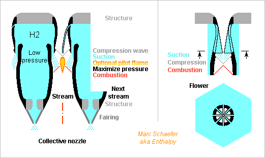
Elements for a pressure-fed hydrogen engine. At the left part, a small bump in the stram's walls provoques a mild compression wave whose amplitude increases at the centre and could approach the pre-chamber's stagnation temperature to ignite the fuel present there, displayed is auxiliary hydrogen. The streams have nearly cylindrical symmetry, so the structure around them and the hydrogen feed don't. Can the main hydrogen ignite alone? Maybe if it evaporates slowly enough. The auxiliary hydrogen keeps much oxygen hot for a local flame. Some fuels ignite more easily: Pmdta ignites at +155°C, before it boils under 1atm, heavy alkanes too, keeping the oxygen hot. Hydrogen must burn at the maximum pressure that keeps the oxygen flow and the suction. This results from hydrogen evaporation, oxygen cooling, combustion, and the stream profile design. No attempted prediction from me. Ideally, most hydrogen would burn at subsonic speed, with De Laval profiles, or at least the combustion would make a compression xave. Throttling worsens the design difficulty. A fairing after the structure eases assembly and cooling. It can leak some hydrogen. Its makes the intricate part of the shape, so the stream walls have cylindrical symmetry and can be mounted by screwing. The right part depicts the already mentioned flower injector. One stream with that injector replaces several smaller ones. I hope the flowers can be deep-drawn from a sheet or electroformed, and welded to the thicker elements by friction or diffusion. Marc Schaefer, aka Enthalpy
-
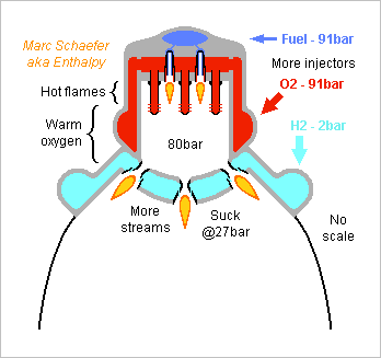
And here's a sketch of a pressure-fed hydrogen engine. No scale, but the dimensions I checked are all favourable. Only few injectors and streams are displayed. The many streams should join their divergents, and some hydrogen be injected where they don't. Angles between the streams shorten the engine, while slow upstream oxygen turns easily. The oxygen injectors could protrude from the side instead, reach nearly the centre, with shorter injectors between the longest ones. This circulates less oxygen in the head where the fuel might freeze, but this doesn't happen at RD-170's gas generator. Whether the many hydrogen moles ignite in the warm oxygen? The progressive evaporation gives a chance. Staged injection can help, or a pilot flame can burn a bit of dense fuel with lower ignition temperature like Pmdta or Diesel oil. A small compression wave could converge to an ignition point. An optional atmospheric insert, no displayed but very useful, can be ablatively cooled. I like the RD-0120 discardable inner divergent in this role because the flow is stable at intermediate pressures too. Pressurizing helium can be stored in the oxygen and dense fuel vessels, as graphite here doesn't favour spheres much. The vessels are bigger, but remain much smaller than the hydrogen tank(s). Some sprinkler provides isothermal expansion then. Or the hydrogen can keep helium cold in a small separate pressure vessel to save good mass. Marc Schaefer, aka Enthalpy
-
I suspect the cited Wiki article is complete cr*p. Either written by a waco or intentionally by some state agency to fool the enemy. Dynamic_armour I want to see the hyperfast electricity source capable of evaporating even a tank flechette - much bigger is possible. Worse, I want to grasp why a vaporized flechette is less penetrating than a solid one. The metal's strength plays no decisive role when a kinetic impactor penetrates an armour. If electricity shall disperse the flechette's mass over more area within tenths of microseconds, it demands more speed hence energy than the round has provided, in itself difficult, and vaporisation increases the pressure of the impact too. The other proposed protective measures, including the cited Trophy Trophy all need a slow small flechette launched by a battletank, but against a valuable battleship, faster bigger rounds would be used. I've been telling for years that fast big kinetic impactors can be built. Just a truck can launch a low-tech 20t missile that flies above the atmosphere and falls on the target. 16t of safe powder give 3.8km/s to the remaining 4t metal that have 700km range, prior to any optimization and staging. That's 20* more squared speed and 200* more mass than the battletank flechette. Or the truck can launch many missiles like a Katiushka did, and each one can be mirved, and the impactor designed to spread when piercing the first metal, so the holes below the waterline are bigger. More efficient, because a ship's armour doesn't need such a huge impactor. Maybe this is the kind of missiles the Chinese built after I suggested it. Anyway, this is the style of weapons against which I want to read an armour of any kind, because a big ship deserves such big weapons, and even bigger ones. The defence against the impactors should also be cheaper than the weapon. Presently, anti-missiles are hugely more expensive, because their target is more difficult to aim at. In a race between dumb mirved kinetic impactors and many supersmart aiming antimissiles, the assailant wins. Until this threat is neutralized, all big surface ships are complete nonsense to my opinion. They were weapons in the mid-20th century, in the 21st they are only targets. This includes aircraft carriers. Insofar submarines aren't detected yet, they still make sense.
-
Injecting hydrogen in the divergent of an engine downstream dense propellants was experimented long ago. But if the dense propellants are pressure-fed, I claim one can build a (mainly) oxygen-hydrogen engine without pumps. This isn't normally done because hydrogen pressure tanks are too heavy. Figures are just examples to help understand and check. From pressure tanks, scalable 1kg/s oxygen is fed in the chamber and burns only 28g/s alkane at 80bar and 1056K. Expansion to 27.2bar converts half the enthalpy available in the hot gas, so the gas can't flow upstream, and it builds a vacuum downstream a sharp obstacle. There, hydrogen ducts end facing downstream, which sucks the hydrogen from 1+1bar in the lightweight tank. 261g/s hydrogen burn in the much oxygen left in the hot gas, the rest of the expansion accelerates the combustion products. 1bar exit provides 3459m/s = 353s and 0.233bar exit 3895m/s = 397s. Less than pumps achieve, but far better than pressure-fed dense propellants, and with reasonable tank mass. I computed with hydrogen burning at constant 27.2bar. This isn't optimum. Some pressure increase is acceptable and improves the performance. How much is a difficult question (and topical at scramjets) and I won't put the necessary time in it. The first expansion to 27.2bar is overkill too. So the performance I indicate is pessimistic. ========== The engine can have one chamber but many convergents, throats and starts of divergent. This lets build one injector per divergent start, for instance to have one hydrogen injector around each hot gas stream, or a more sophisticated section like a flower. All streams can then converge in a common end of divergent built as usual, cooled if needed by hydrogen or oxygen. At an atmospheric stage, an atmospheric insert and a wider nozzle, as at the RD-0120, improve very much the small expansion. Graphite tanks are very desirable. Alkanes outperform minimally their amines homologues, high strain or unsaturation improve only 1s. The chamber's walls need some cooling by the oxygen. The RD-170's gas generator can inspire the chamber here, including wall cooling, but I would leave a common room to the slightly oxygen-rich flames and inject most oxygen further downstream as I suggested there, possibly without swirl scienceforums and then ignition doesn't need pyrophorics, something like Diesel glow plugs would suffice nasaspaceflight 28g/s alkane need active cooling of the chamber's walls to leave 823K = 550°C at hydrogen injection. This was to ignite permanently the hydrogen in the quick stream, but I forgot cooling by hydrogen. More alkane can help stabilize the hydrogen flame. Pilot flames with alkane at hydrogen injection can help too, or staged hydrogen injection, or some local recompression shocks. Alkanes with an at least C4 unbranched tail have a low autoignition. Or Pmdta ignites at only +155°C in air. Farnesane stays liquid around -100°C. Heavy by-products of an alkylation unit shouldn't be bad. To pressurize the hydrogen tank, a fluid can circulate in heat exchangers between the chamber and the tank, or an electric pump can scoop some liquid hydrogen, send it to a heat exchanger at the chamber, and to the top of the tank. Or the divergent, just upstream hydrogen injection, is a milder place than the chamber. ========== Some ideas here apply to scramjets too, especially the many streams, each with hydrogen suction or injection, which ease the mixture and shorten the engine. Some ignition methods apply too. Check also chemicalforums ========== A sketch should come, maybe some more figures. Marc Schaefer, aka Enthalpy
-
Gas Generator Cycle for Rocket Engines - Variants
Enthalpy replied to Enthalpy's topic in Engineering
Here's an example of reheated gas generator cycle with peroxide as in the last message. 64% concentration (70% can detonate, my mistake) burns a fuel to heat the decomposition. This combination is as efficient as peroxide dangerously concentrated to achieve alone the same temperature. The fuel in tiny amount can be chosen for practical reasons: safety, contact ignition with peroxide, autoignition temperature, identical to a main propellant. The turbines are in series hence not developed independently. It worked for the Vinci. Scalable 1kg/s peroxide plus 30.5g/s Pmdta make 973K=700°C in the auxiliary flux, expansion from unoptimized 80bar to 2bar accelerates to cumulated 1402m/s or 1013kW harvested by a turbine. With reheating, compare: The first expansion to 20.6bar accelerates to 958m/s or 473kW. A turbine stage harvests the expansion. Additional 13.6g/s Pmdta reheat to 973K=700°C. Expansion to 6.0bar accelerates to 918m/s or 440kW. A turbine stage harvests the expansion. Additional 12.7g Pmdta reheat to 973K=700°C. Expansion to 2bar accelerates to 872m/s or 402kW. A turbine stage harvests the expansion. Expansion to 1bar provides some thrust for roll control. 1315kW are available instead of 1013kW but added Pmdta makes the auxiliary flux 1.026* as heavy. At identical auxiliary consumption, 1.266* as much power multiplies the chamber pressure to gain 6s Isp. A single re-heat would gain 4s. 6s is as much as a super-fuel brings, it does carry more payload. Adding a fuel allows a peroxide concentration that doesn't detonate, by itself very useful. If the auxiliary propellants ignite by contact, the engine starts and re-starts easily. A separate turbine to pump the main fuel lets adjust its proportion by the amount of auxiliary fuel. Two turbine stages provide a better speed for the oxygen pump. At a gas generator cycle for hydrogen, reheating brings only 3s because added oxygen makes the auxiliary flux quite heavier. Marc Schaefer, aka Enthalpy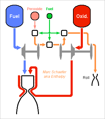
-
Neanderthals Built a Water Reservoir
Enthalpy replied to Enthalpy's topic in Evolution, Morphology and Exobiology
Good opportunity to warn everyone here that when a psychiatrist investigates a target person, he uses intermediates on the street, the Internet, and among the relations, to conduct tests. These intermediates are sometimes other customers, or often accomplices of the secret police. Among the recurring tests, at least in France and Germany, are the opinions about extraterrestrials. Presently, nearly every astronomer, every scientist supposes that extraterrestrials exist. But for psychiatrists, who have as much to do with science as fish with rollerblades, believing that extraterrestrials exist is a sign of madness. ========== Dear Mark, even if most sensible persons suppose that ET exist, a visit of Earth by ET is not the same. Distances are vast, and there are many planets. All species learn and evolve, not only hominids. Apes, some birds... learn and transmit behaviours or tools that are not determined by the genes. A bonobo can learn a new tool from an other group and teach it to its group, after which this knowledge is part of the group's culture. If you observe the intelligence of some cats, of ravens, octopuses, dolphins... it's not so far from what Sapiens are capable of, and they need no intervention from ET, as we can observe. So maybe ET visited Earth, maybe they transmitted some knowledge, but I would need evidence they did it to believe it, rather than lack of evidence they didn't. -
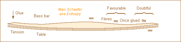
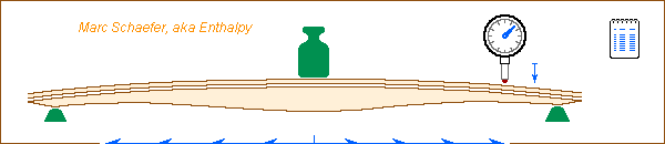
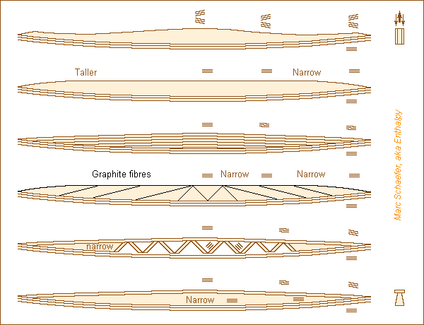
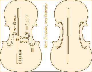
The violin family has a long bass bar that is glued under the table and passes below the left bridge foot. It's usually made of Picea abies (Norway spruce). Most luthiers give the bass bar tension: its ends are typically 1.5mm away from the table's curve when the centre touches it. The bass bar is then glued with a permanent elastic deformation of both elements, said to drop over decades. The bending force of the bass bar alone is around 10N. The strings press about 0.40*400N=150N on the table, so the help by the initial tension is unimportant. This paper finds that 1.5mm bass bar tension raises some violin's resonances by a semitone, and 3mm tension by a full tone SkrodzkaLindeKrupa which definitely changes the sound of a violin. Damping is unaffected. That study observes a 10dB increases in the 4-5kHz violin's response CroenAtwood and that stress doesn't change the resonant frequency of two wood stripes glued together. This is consistent with a linear behaviour of wood. It seems paradoxical: stress doesn't change resonant frequencies, but tension does. ========== My incomplete explanation: wood is anisotropic, and the fiber orientation in the bass bar differs with and without tension. A phone book is easy to bend when the pages are loose, impossible when pressing the pages together. In wood bent elastically, shear stiffness hinders the fibres from gliding reversibly against an other. Picea abies has little shear stiffness: GLR is 20* smaller than EL, the stiffness of fibre elongation. Hand computation fails at the shape of a bass bar, but if a beam's length is less than 20* its thickness, shear matters more than elongation. Same if a beam's centerline deviates more than 1/20 from the fibre direction, or if the section varies faster than 1/20. The bass bar is in these cases, the table too. In the "Favourable" zone, tension orients the fibres nearer to the section's centerline and upper edge. The bending angle is small and unknown to me, the upper edge has a bad orientation, this zone is thick and short, and we speak about a semitone hence 12% stiffness, so I won't risk figures. In the "Doubtful" zone, tension orients the fibres away from the centerline, wrong direction. But it also lets the bar's fibres meet the table's fibres with an angle, which improves the stiffness of both elements. I'll risk figures even less. One could try anisotropic FEM modelling. I'd prefer someone to devise experiments, maybe with a simplified "table". ========== Be my explanation of tension effect right or wrong, the present shape misuses the properties of Picea abies. So can the bass bar improve by using the material better? Not to raise the resonances, but to make the bar lighter and the instrument louder. Acer platanoides and others bring a bigger GLR but are denser. I trust luthiers to have tried and abandoned them. Paulownia tomentosa seems favourable to bass bars and tables, little thicker than Picea abies. I have no figure for GLR, and is it available quarter-sawn? One guitar luthier is enthusiastic. Assemble plywood from Picea abies and hide glue. The usual +1/2 -1 +1/2 plies, or +1/2 -1 +1 -1 +1/2 etc, but not the usual +-45° directions. Rather +-1/10 slopes, resembling the bass bar and the table. Keep the bass bar high, make it narrow where it was thin (keep wide ends for the glue). At identical h3W, the bar is lighter, and the fibres are less cut. Make a laminate beam from Picea abies and hide glue. Bend the centres of the stripes, glue the stripes applied on a pattern, cut a bass bar out of that, narrow preferibly to thin. Make a narrow beam of Picea abies, add few graphite fibres on the top and tilted at the sides where stiffness needs them. Spread them more than sketched. Graphite fibres alone aren't as efficient as sounding wood, but over a light kernel they are better. If possible, I'd prefer hide glue over epoxy, for known damping and ageing. Make a truss of Picea abies operating in the fibre direction. How much work? Make a T-profile of Picea abies, with the top well oriented and the centre thin. Adjust the top's thickness. ========== This setup would measure the flexibility to let a new bass bar reproduce an existing good one: It should use a real table, sorry for that, as glueing the bass bar on a model beam would be inaccurate even for a comparison. If mounting the table upside down, a narrow bar might buckle to the side. The positions of the weight, supports, measurements need precision. A milling machine would be perfect, with stops for the table and the weight, or a 3D printer if controlled accordingly. The deflection has to be significant. More support positions, further inwards, possibly with a heavier weight, give better measures near the centre. One could even move the supports at constant distance from the deflection point. Once the lighter bass bar gives the same stiffness, the resonances are too high, so the bass bar must be trimmed to the desired frequencies. ========== Trimming the resonant frequencies may hopefully be done at the table with bar, without the rest of the violin, by glueing temporarily a frame, about as heavy as the bottom plus rim and neck, where the ribs use to be. This won't reproduce perfectly the violin's resonances, as the enclosed air and the interactions are missing, but let compare with a known good bass bar. Such frames would also let reproduce good bottoms and good tables without the bar, better than when these elements are alone. Marc Schaefer, aka Enthalpy
-
A motorised tuner exists for guitars since 2012 or earlier, and nobody tells me a word. Tronical produces it, others maybe too tronicaltune and some guitar manufacturers integrate it under their own name Gibson It's available separately too, for 250€ or 300€ at Tronical. Many people own a guitar, but a decent musician tunes his guitar quickly and not so often. Harps would need a tuner badly, as I suggested in this thread. 250€ for 6 strings seems expensive. That would scale to 2000€ for 47 strings, but costs and prices aren't proportional. 1000€ seem attractive to save 15min every day, and my previous computation tells that 2000€ are quickly profitable for a professional harpist. The motorized tuning hammer I suggested previously should be cheaper but slower. A harp needs perfect reliability. Some strings break if tuned a semitone too high, and if several strings are too high, the table may break. So the instrument must distinguish the strings and tell if a pedal is engaged. Involving the harp maker in the development seems better.
-
The holes in the box of an instrument (F-holes, for the violin family) must fit many constraints. Their inductance knowingly tunes the Helmholtz resonance, together with the volume. The inductance depends on the width too: a narrow long hole needs less area. Air friction at the rim usefully dampens the Helmholtz resonance. A narrow long hole is more efficient, a rosace even more. Too little investigated. They give the plate flexibility. Little at the guitar, much at the violin family. Their shape shall alleviate the stress concentration. I tried a cello with three pairs of round holes instead of two F-holes, which neglects the points 2 and 3. The lowest resonance was brutal, and the next ones too high. I hated the sound, some customers liked it. The strings of the violin family press strongly on the table, and holes nearby concentrate the bending and shear stress where fibre orientation is unfavourable. Elongated holes with sharp ends worsen it, as known in mechanical engineering. Despite being narrow, the F-holes provide a big radius at their bent ends and they shelter the tips where the holes reduce the stress. Violins built three centuries ago, with a higher bridge meanwhile, still play. Few shapes fit this job. An other instrument retains the bent ends, but as a C shape instead. Would longers holes and the more mobile table make louder violins? Sound quality would need a thicker bass bar and other re-adjustments. Marc Schaefer, aka Enthalpy
-
I suggested here on January 22, 2019 to replace the violin family's purfling by graphite fibres glued on the wood scienceforums Though, the purfling makes the table's and bottom's rims more bendable. Or rather, the groove makes the wood more bendable, and the purfling doesn't add significant stiffness. This is more important at the table and bottom's ends, where the fibres arrive perpendicular to the bracings. Imagine the groove removes one half of the wood thickness over 1.25mm: there, the table and bottom bend as easily as 1.25mm/(0.5)3=10mm extra length. Suppressing the groove raises a violin's resonances a bit, perhaps by a semitone. It also makes the table and bottom less mobile. So I propose, if replacing the groove by graphite fibrers on one or both faces, to make the table and bottom thinner in this region. Numerically, this shall keep the sums of L/e3. With random figures, 1.25mm/(1.3mm)3 + 5mm/(2.6mm)3 could become (1.25mm+5mm)/(1.9mm)3.
-
At the APU of Apr 08, 2013, I want copper to conduct the heat to the bar ends scienceforums but longer machines can't. The known answer of last message is to interrupt the iron (short for "magnetic material") to let air flow at several places. No need here to flow a coolant within the wires. Such a design scales to any diameter and length. It circulates clean inner air among the active parts for reliability. One variant would stack a simpler shaft, spacers for air flow, and the rotor iron. At the APU, I supposed stator iron working at 2.4kHz and peak 1.8T between the slits, but I don't have any doc for such a material. The present cooling design lets lengthen the machine for smaller induction if needed. Starting from 3*0.25t to replace a 7t Trent, even a double length would remain an excellent deal. I still like voltage plateaus from the APU that feeds a rectifier. A motor should have the usual refinements: fractional pitch, skew and so on. The induction could also be axial and the bars radial. Rotor and stator disks alternate then as in a turbine. The active material fits in less room, but is hard to cool and assemble. Small angles between the stator disks with one inverter each would run more smoothly. The current fashion replaces wound synchronous motors by squirrel cages, but I believe permanent magnets make lighter machines. Marc Schaefer, aka Enthalpy
-
In the last message, I claimed motors for airliners can use magnets and copper, without superconductors. Without a new design, arguments can be scaled from my APU: scienceforums For sleek tanks and spread thrust, I propose to replace two Trent motors by six 20MW motors, as on the silhouette there scienceforums Lossy aluminum cables transport limited power only if some tanks, fuel cells sites, motors or fans are broken. To scale the 20MW motor from the 1.27MW APU, keep the 200m/s azimuthal speed, the length and the thicknesses, multiply the gap diameter to 1.2m and the number of poles. The excellent efficiency remains, and even air cooling at the bar ends. The mass scales to 250kg without shaft nor casing. The tanks and fans are somewhat wider than 1.6m, so the motors fit. A gear doesn't look necessary. Or each nacelle can have two D=0.6m 10MW motors, scaled from my APU, and possibly two counter-rotating fans. Same length, thicknesses, efficiency, air cooled too. Easier to integrate, may need gears. Or accept some more mass. Increased thicknesses conduct electricity and heat better, so the copper bars can be longer and keep simple air cooling at their ends. The diameter shrinks. Or distribute the cooling, if reliability is kept. Some alternators interrupt the magnetic circuit to let air flow radially over the copper bars. Longer bars reduce the diameter. 6MVA components and inverters exist for railway engines. I'd group the poles to use 4 inverters and avoid components in series and parallel. Instead of switching at a similar frequency a PWM for a slow motor, the inverters provide my waveforms at 2.4kHz downstream a voltage regulator scienceforums especially scienceforums Marc Schaefer, aka Enthalpy
-
One can build instruments for the same pitch with varied bore width. Essentially, the range is smaller when the bore width is inadequate. The tubax is one example. One of them goes as low as the Eb contrabass saxophone but is a wide as a tenor or baritone. The mouthpiece and reed must match the instrument. This is commonly done at woodwinds with reeds more or less big and stiff, with mouthpieces more or less open. The instrument's height wouldn't impose the bore through the reed and mouthpiece's dimensions.
-
In a rescue operation by helicopter on rough seas, the boat or the person may move a lot, making it difficult to jump on the cable. If not already done, I suggest to let the cable's tip follow the boat's movements when near to it. A winch is already there, the distance sensor could be a radar as on cars to park more easily, maybe the very car radar. The sensor or its data processing may need refinements to detect the hull rather than the approaching person. Once the vertical movements follow the boat, the person can catch the cable's tip to suppress horizontal relative movements, if the cable is light enough. Maybe the cable's tip can follow the boat's horizontal movements too. This goes more easily at a quadcopter or hexacopter, which can have >=3 cables and as many winches attached far apart at the wide aircraft, to build an inverted pyramid. The aircraft itself might follow the boat's horizontal movements. This is easier with the tilted rotors I proposed in the previous message. I believe a single cable is to difficult, better the inverted pyramid. Marc Schaefer, aka Enthalpy
-
A wide bore eases low notes, a narrow one high notes. That's quickly checked by sounding a few tubes like a Pan flute. The tenor, bass and contrabass trombones confirm it. Theobald Boehm chose early, as a compromise on the flute's 3 octaves range, the 19mm bore that persists today. Can physics explain this? The radiation resistance of a small source increases like F2, the reactance X of a tube of constant length like F, and the friction and heat loss resistance of the air against the walls like sqrt(F). The Q-factor X/R drops at high and at low frequencies, but do figures match? R fits P=RI2 with I in m3/s rms. I adapted known formulas to a cylinder, not a cone, where I varies as a sine of the position. A woodwind's holes are lossy too, but simplicity lets me neglect them, big error source. For the flute's lowest C=262Hz, the lambda/2=2L air column is ideally 0.67m long and D=19mm wide. Friction and heat dissipate R=13kohm while a single end radiates negligible 0.4kohm. X=0.12Mohm per lambda/4 provide Q=18 only. For the flute's high C=2093Hz, the first big open hole is a C at 0.33m or 8 lambda/4 from the ideal blowhole position. The air column does vibrate down to the open G#, F and further, but how strongly? I neglect that, big error source too. A single end would radiate 49kohm, I take 98kohm for both because 2*lambda separation lets them interact little. Friction and heat dissipate 18kohm. Over the 8 lambda/4, X=9.4Mohm provide decent Q=81, but an other limit appears. If the end of a 100 waves long air column provided no reflection, Q would still be excellent, but the oscillation would be impossible. So I compare with the D=19mm column's 1.5Mohm wave impedance. 49kohm radiation reflect only 0.94* the wave pressure at each end, or 0.88* on a round trip. At G=3136Hz a fifth higher, where emission becomes badly difficult, 108kohm radiation let *0.75 the wave pressure on a round trip, hindering oscillation. This effect, well studied at brass flares, differs from Q. I define E=Zc/R where R cumulates the radiative losses, here R~98kohm, then E=15 for the high C on a flute. I would not compare with Q=18 to predict some optimum bore width. More limits exist: competition with lower resonance modes, and friction losses at the tone holes, which aren't much shorter than lambda/2pi. The adequation of the air column with the blow hole must matter even more at flutes. ========== The bore D would scale like sqrt(lambda) for instrument family to keep the lowest note's Q. The alto flute would scale to 22mm, but it's rather 24mm, even 26mm at Boehm's trials. Favouring the alto's role, the low notes, is a good reason. Trying to compensate its inadequate blow hole wouldn't. The piccolo would scale to 12.7mm, but its low notes are sacrificed. According to sqrt(lambda), the Boehm bass clarinet to written low C scales to 23.2mm, rather 24mm on existing instruments. The contralto scales to 28.4mm and the contrabass to 32.8mm, but both existing instruments have 30mm. ========== Low instruments have a broader range, as an observation. My explanation is that, once the bore scales like sqrt(lambda) for Q at the low notes, the highest note scales its lambda like the bore to keep E. A tone added to the low range loses only a semitone of the upper range. So a piccolo flute scaled to 11.3mm bore to play decently down to F# rather than C, a frequency 2.83* higher than the soprano flute, would reach decently up to A rather than C at same difficulty as the soprano flute, and hardly extend beyond C. This resembles the observation. A Boehm bass clarinet with written low C scaled to 24mm bore would reach notes written 3 semitones higher than the soprano at identical difficulty. Marc Schaefer, aka Enthalpy
-
More nice cornetto records. Andrea Inghisciano 3b3Cl8xWECA - CCP07iEUQo8 David Brutti tV2iQvul_ZM - adiXxVoIsE8 - rQPhJZpr3FA Check their channels, linked there. Gustavo Gargiulio CI977EnnBM0
-
A superconducting motor for aircraft was developed in Russia Russia Today (in French) and these search keywords produce 1 million hits: superconductor aircraft motor with many companies and agencies involved Rolls-Royce - Moscow Aviation Institute - and more Many target electric power transmission from few gas turbines to distributed thrust. This lacks ambition. Distribution saves power but still emits CO2, despite we have no time to waste. The future is hydrogen tanks and fuel cells, as I described in this thread, and it needs little development. Car fuel cells can fly right now, aircraft should lighten them more radically than cars needed to. By the way, a hydrogen-fed gas turbine consumes inherently twice as much hydrogen for being a thermal engine and is nonsense. I suggested aluminum wires in aircraft. They make reliably all terrestrial power lines, so aircraft manufacturers could wake up scienceforums - scienceforums Reliable connectors may need some R&D, but thereafter I'll trust aluminum better than superconducting lines. Helicopters and quadcopters should adopt hydrogen tanks and fuel cells even before fixed-wing aircraft do, as they need them for flight duration and range scienceforums I described an APU generator with permanent magnets and copper wires, without gears: scienceforums and see no need there for superconductors that add failure modes. Electric machines improve directly with azimuthal speed. They also improve with size, so generators bigger than an APU work even better. I described waveforms for high-frequency inverters in an other thread, that's low-tech development scienceforums especially scienceforums In this thread, the motors I propose for propellers and fans have either a (reasonably) big diameter or a gear. A superconducting motor brings both together with efficiency, but I would not accept the added failure modes. A geared quick electric machine with copper windings is extremely lightweight, small, efficient, reliable. Humans know to build gears now, whose wear can be checked. This avoids the random risks added by superconductivity. My electrostatic machines too are efficient at low azimuthal speed. They aren't on the clear web any more, as Saposjoint and Physforums closed, but are on my CD saposjoint - physforum - lofi.physforum (dead links) I didn't check what they bring to aircraft motors. They add failure modes linked with airtightness, as superconductors do, and they add high voltages, but need no cold.
-
When a separate flux of propellant(s) is turbined and dump, it's a gas generator flux. If the whole flux of a main propellants burns partially in a prechamber and is turbined upstream the main chamber, it's a staged combustion cycle. But when a separate flux of propellant(s) is turbined and dumped in the main chamber together with the main propellant fluxes, let's call it an integral gas generator. What isn't stupid in my proposal? Pressure vessel(s) can store the auxiliary flux(es). Start and re-start by opening valves, especially if a catalyst or mutual contact ignite the auxiliary flux(es). The auxiliary flux remains hot as it enters the main chamber and can ignite the main propellants. Some propellant added locally can help. Permanent ignition can enable faster main propellants speed, hence a smaller main chamber. No propellant mass is wasted. Main 100bar from 210bar or 350bar pressure vessel outperform a gas generator cycle at 140bar, already with steel tanks, clearly with fibre tanks. The integral gas generator is less efficient than a staged combustion, but it's a lot simpler, especially with clean auxiliary propellants like hydrogen peroxide, maybe amines mixes. Turbine speeds are easier than with a gas generator cycle, and they fit the pumps better. Membranes in the pressure vessels let start the pumps in zero gravity. Thrust from the auxiliary flux(es) can suffice to push the main propellants in the tanks' outlet. The auxiliary flux(es) can also provide attitude and orbit control to an upper stage after the main engine stops. 84% to 88% peroxide over a catalyst provide a reliable temperature that fits turbine alloys. 70% peroxide can't detonate but needs a fuel supplement for temperature. Maybe an amine, possibly unsaturated, brings hypergolic ignition. The amines mixes I propose elsewhere as alternatives to peroxide must first be tried: do they recompose where desired? One turbine per main propellant would reduce the speed further. Injecting optionally some propellant between both turbines adjusts the mix ratio of the main propellants. A sketch may come or not. The cycle is easy to imagine anyway. Marc Schaefer, aka Enthalpy
-
My bassoon balancer v5 adds adhesive tape in two directions to hold the triangular ring closer to the body. This limits the stressing angle where the two previous tapes cross and hopefully spares the tapes. The method to superimpose tape plies applies further. A professional embodiment would use durable materials like polymer film (Mylar etc) or fibres, good glue (like epoxy), something lighter than the thick steel triangle. It would also prevent carrying the instrument only at the tenor joint. The shape of the part could be open, or completely different, with one other part on a strap originating at the boot fitting at the part at the tenor joint. Marc Schaefer, aka Enthalpy
-
Gas Generator Cycle for Rocket Engines - Variants
Enthalpy replied to Enthalpy's topic in Engineering
I suggested to re-heat the work fluid between two turbine stages at an expander cycle scienceforums and the same applies to the staged combustion cycle and the gas generator cycle. The gas generator cycle benefits most because its strong expansion cools much the working fluid. The red propellant can be an oxidizer like liquid oxygen, pink hydrogen peroxide about 86% for turbine temperature, green n-dodecane, blue a fuel. The pink and green propellants can be pressure-fed for easy start and restart. The amount of green propellant adjusts the ratio of red and blue propellants. Cycle variants: Coupled shafts, or a single shaft, enable balanced expansion ratios, more efficient. Turbining first for the more bulky propellant consumes minimally more green propellant but leaves slightly more thrust at the dump nozzle. Other reasons can decide. Some green propellant could be added right before the dump nozzle to push slightly more. Other reasons can decide. Propellants variants: Peroxide (pink) only 70% concentrated can't detonate and can combine with a fuel, preferably hypergolic. The green propellant preferably auto-ignites at low temperature. Linear alkane, long amine... As pink propellant, recomposing amines are as efficient and maybe safer than peroxide, as I described elsewhere - if they recompose where desired. The green propellant is then an oxidizer, maybe nitric acid. The main propellants could make the working fluid, but a bearable temperature often demand a dirty and very inefficient mix. Other functions: Pressure vessels can host the pink and green propellants. A catalyst can then start and restart the engine by merely opening valves. Derived pink and optionally green propellants can also ignite the main chamber, by contacting an other or over a catalyst. Membranes in the pressure vessels let start the pumps in zero gravity. The dump nozzle can suffice to push the main propellants in the tanks' outlet. The pink and optionally green propellants can also provide attitude and orbit control to an upper stage, even after the main engine stops. Marc Schaefer, aka Enthalpy
-
Engineering is very difficult. If their rocket shows only one or two failure causes in a flight, it proves that SpaceX didn't develop it so quickly. I'd say quite the opposite: they spent the necessary time on design, design reviews, triple checks, AND experiments on parts and assemblies. Compare with other launchers: they too fail a couple times among the first launches. SpaceX's statistics aren't so different. And when creating a completely new technology, which reusing rockets and landing them definitely are, an individual or a company fails many more times than when just scaling up an existing design. What does differ is that Musk is a physicist / inventor / etc, not an ignorant manager who believes plain nonsense like total quality. Having developed technology himself, he knows that only experimentation debunks design mistakes, and that failure just belongs to the process, after the developers did their very best to avoid it. Also, SpaceX analyse and correct the failure causes much more quickly than Ariane for instance. This may result from their culture: acknowledging that failure belongs to development makes this step easier than if some manager imagines that total quality avoids failures, and that mistakes result from faulty engineers.
-
Norwegians buy many electric cars, so we only need a user to testify. I bet the problem is solved, or it would be a no-go there.
-
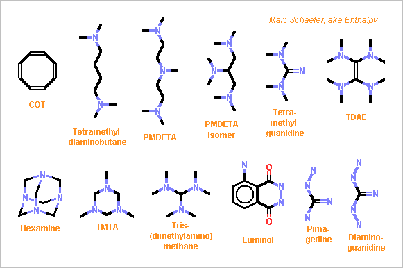
Hello everyone and everybody! Some rocket engines inject a small amount of a third propellant that ignites by contact with one main propellant. For instance the RD-170 and heirs start with the liquid oxygen and some triethylaluminium followed by the "kerosene". The RD-170 had little choice. Much liquid oxygen immediately quenches the many flames in its gas generator, demanding as many ignition sources, easier with the hypergolic pair. But triethylaluminium ignites upon air contact, as probably do all compounds igniting with liquid oxygen. That's badly dangerous near 500t of fuel and oxygen. I propose here to add two hypergolic propellants for engines whose design fits. Not igniting with liquid oxygen, each can be less dangerous. Coupled positive displacement pumps and optionally an electric motor can dose them. Or optionally, if the main fuel is more reactive, like an amine, one extra oxidizer may suffice. I still prefer the Diesel hot plug and the preheated propellants I described there nasaspaceflight on 01/13/2012, 01/22/2012 and around and also H2O2 over a catalyst then mixed with any fuel scienceforums hypergols are just one option more. ========== Oxidizer N2O4 is a rocket standard, it ignites quickly most amines and more fuels, but is badly toxic. Fuming HNO3 ignites quickly most amines and more fuels. Slight dilution improves its unhealthy fumes. Each 10% water lose only 200K from the >3000K flame, so the ignition delay decides. H2O2 ignites most functionalized fuels, and even "kerosene" with a delay. 70% concentration doesn't detonate without fuel and still provides a 2700K flame, perfect if ignition is fast. ========== Fuel The solids here can be dissolved in other fuels. Unsaturated hydrocarbons ignite in peroxide, but rather slowly. COT is highly unsaturated. Alcohols ignite, not so quickly, and polyols are viscous. Tertiary amines ignite quickly with N2O4, HNO3 and hopefully with H2O2. Few examples, a chemist would propose many more: Tetramethyldiaminobutane is a known example, nearly as swift as MMH. Fp=+46°C isn't perfect, and tetramethyldiaminohexane is toxic. Pmdeta should ignite as quickly, it has nice physical properties, and is an advantageous main fuel too. Its isomer might result from glycerine and dimethylamine. Tetramethylguanidine brings Fp=+60°C, mp<-30°C, 1.4mPa*s. TDAE already reacts slowly with air. Fp=+53°C but reportedly very flammable. Hexamine and TMTA are amine-rich, tris- and tetrakis(dimethylamino)methane too. Hydrazines ignite swiftly with N2O4 but many are very toxic: hydrazine, MMH, UDMH... Exceptions exist: Luminol reacts at room temperature with oxidizers. Pimagedine. Diaminoguanidine? Their methylated variants? More ? Imines? Marc Schaefer, aka Enthalpy