


THX-1138
-
Posts
129 -
Joined
-
Last visited
Content Type
Profiles
Forums
Events
Posts posted by THX-1138
-
-
On 11/6/2018 at 12:18 PM, studiot said:
So why didn't you think this through in the first place?
There is an arrangement like you are trying to describe, used in some helicopters with contra rotating main rotors to balance the spin torque and avoid the need for tail rotors.
I suggest you look it up.
I imagine the rotors are designed to have low moments of inertia and use their lift properties to counteract any precession effects caused by tilting the axis. I'm actually asking about the other end of things; coaxial spinning disks with high (and equal) moments of inertia, and high angular velocities -- what happens if an attempt is made to tilt the axis?
0 -
On 11/6/2018 at 1:49 PM, THX-1138 said:
I'll probably get slapped around for this, but I'm looking for moderately dumbed-down texts about magnetism. The sort of 'whats' and 'hows' I want to know include things like
- What [common] materials make the best electromagnets? (I.e., most powerful when energised. least retained magnetism when de-energised.)
- What are the best materials for an air-cored electromagnet closed at both ends (such as for an oscillating actuator)?
- If I use electromagnets along an air-core channel, what should the spacing be? The strength? What do the field rise and fall curves look like (so the next can be energised with minimal loss to the falling field of the previous one. Where in the travel of the magnetic core should one trip on, or off?
- What sort of material would one use for the slug in an air-cored actuator? Iron? Steel? Ferrite? A neodymium magnet?
All those, and then I'd like to understand the 'why' (or 'why not') aspects of each. But I don't know the terminology to ask for what I don't know.

I see I was unclear.
- What [common] core materials make the best electromagnets? (Concentrate the field best, but for which the persistence of any induced field is minimal.)
- What are the best materials (e.g., PVC, paper/cardboard, non-magnetic metal) upon which to wrap windings for an air-core electromagnet? As in, the hollow cylinder upon which the windings are wrapped?
- Okey, good to come back to it.
- If the device in question is a hollow cylinder with multiple successive windings along its length, and the goal is to energise the windings in such a way as to propel or position a slug along the interior of the cylinder, should the slug (presumably of a magnetic material) have its own field, or be made of something in which an induced field is unlikely to persist?
I hope that is better.
And as for learning about magnetism from scratch, StringJunky, what source(s) would you recommend?
0 -
I'll probably get slapped around for this, but I'm looking for moderately dumbed-down texts about magnetism. The sort of 'whats' and 'hows' I want to know include things like
- What [common] materials make the best electromagnets? (I.e., most powerful when energised. least retained magnetism when de-energised.)
- What are the best materials for an air-cored electromagnet closed at both ends (such as for an oscillating actuator)?
- If I use electromagnets along an air-core channel, what should the spacing be? The strength? What do the field rise and fall curves look like (so the next can be energised with minimal loss to the falling field of the previous one. Where in the travel of the magnetic core should one trip on, or off?
- What sort of material would one use for the slug in an air-cored actuator? Iron? Steel? Ferrite? A neodymium magnet?
All those, and then I'd like to understand the 'why' (or 'why not') aspects of each. But I don't know the terminology to ask for what I don't know.
Links to references sources would be great?
Thanks!0 -
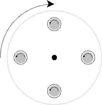
Actually, the grey circles show the direction of rotation to be contra to that of the larger wheel; it didn't come out clearly in the diagram, I guess. The axes of the smaller gyroscopes are parallel to that of the larger one; they are all parallel to the [latex]Y[/latex] axis. AND I clearly stated that the small discs were rotating contra to the large one (widdershins vs clockwise).
I am not a mathematician, so my gut feeling is that, since there are no precessional forces at play when the experiment is in its unstressed state, all of the gyroscopes having parallel axes, so my first question would be about that behaviour, and the effect of altering rotational velocities.
The diagram is a top-down view. I'll take your word that 'effects' would cancel out on opposite sides of the large disk. Which effects, though? And what would happen if force were applied to, say, rotate the structure around the [latex]X[/latex] axis?
0 -
All right, I will. I didn't think of that example.
Why are you being so unpleasant? Were you born knowing everything? I'm sorry I wasn't. It's rather a put-off to ask questions here to get slapdowns like the above.
0 -
They're welded into a framework containing them both, not to each other.
0 -
Replace 'flywheel' with 'fairly massive disc,' and 'counterclockwise' with 'counterclockwise when viewed from above.'
0 -
I'm being serious. I'm wondering about the situation of freedom being restricted in two of the directions of precession.
All right, either the spindles are Klein manifolds
") or some engineering ingenuity is used to get the wheels, spinning each on its own spindle, as close as possible and welded into a single unit, so precession forces will apply to the entire structure.
0
or some engineering ingenuity is used to get the wheels, spinning each on its own spindle, as close as possible and welded into a single unit, so precession forces will apply to the entire structure.
0 -
The larger wheel and its spindle are one piece, and are spinning; assume frictionless bearings for normal conditions. The bearings of the smaller gyroscopes' spindles are fixed to the larger wheel, but the wheels themselves are free to rotate upon those spindles.
0 -
Irrelevant. Assume the spindle is turning, and is being suspended in touchless magnetic bearings and driven by magnetic induction motors. Assume frictionless under normal circumstances.
0 -
Posit a flywheel as a gyroscope, rotating clockwise
Now consider the flywheel pierced at regular intervals aeound the circumference, and in each piercing there is another gyroscope rotating widdershins. and that the sum of their angular momentums is equal but opposite to that of the larger flywheel.
[latex]\sum_{1}^{4} L(small~gyro~n) = - L (large~gyro)[/latex]
What behaviours or peculiarities could be expected from such a framework, even before force was applied to the [latex]Z[/latex] axis?
 0
0 -
Suppose you have a heavy flywheel rotating about a spindle in thr [latex]X[/latex] axis at a considerable rate of radians/sec.
Now suppose you have another one on the same spindle -- same mass, same diameter, etc, but colocated and rotating in the opposite direction.
What will happen if force is applied to rotate the spindle about the [latex]Z[/latex] axis? (I'm guessing lots of resistance, leading eventually to catastrophic heat transfer.)
0 -
I recently purchased some 7Ω 1% resistors and used one in a circuit. However. my digital multimeter says it's closer to 11Ω, which is 'way outside the 1% tolerance. My meter isn't top of the line, so this made me wonder: How much can I trust it, and for that matter, how can I trust any meter readings?
How typical is miscalibration in low-end measurement devices? Or should I trust the meter and gritch at Mouser that the Vishay resistors they sold me are monstrously out of tolerance? (Or at least one of them; I haven't checked all of them.)
Thanks!
0 -
Maybe I should start a new topic for this, but the wealth of knowledge exhibited here is too awesome.
- Many introductory materials talk about (and use in illustrations) 'lines of force' when covering magnetism. Is that an accurate concept, or a fiction for illustrative purposes? Are there actually discrete force lines, or is it a continuous field?
- I'm looking for materials that, when used as the core of a coil, will strongly enhance the coil's magnetic effects. However, I'm looking for materials that will retain as little as possible of any induced magnetism -- and other materials that will retain as much as possible. I don't know what terms to use nor where to look; can anyone provide we with some links or pointers?
Thanks very much!
0 -
I have no idea if it would work, but could a separate system help drop the temperature through spray cooling?
How about using a Ranque-Hilsch vortex tube?
0 -
Should I have asked in the Physics forum, maybe?
0 -
I can recommend the book Easy Steppin' from Square 1 if you can find a copy. Maybe at ABEbooks.Com or a used bookstore.
0 -
Two related cases involving multiple coils around a cylindrical barrel. Two separate goals (but probably related math):
- Coils are activated in sequence to accelerate a magnetic object down the bore. Think 'Gauss-pistol'.
- Coils are activated (possibly with polarity reversal at/as needed) to smoothly accelerate a magnetic plunger down the bore -- and maybe cushion it when nearing the ends. When it reaches one end, the process is reversed to accelerate it back to the other end. Think 'rectilinear actuator'.
Physical feedback (e.g., optical interruption) about the object's position in the bore is my first preference, since fancy harmonic circuits aren't my forte.
I'm basically curious how the coils' fields should build and decay relative to the object in order to get the best effect (e.g., so one field's decay doesn't interfere with the next one, or 'suck back' on the object in the bore).
Digital circuits, microcontrollers, A/D thresholds, etc. -- these I can do. The magnetic field stuff, though, is right out of my experience.
I know this is kinda rambling and unclear, but any feedback, comments (constructive), or pointers would be extremely welcome.
Thanks!
0 -
I don't know what the 'p != np' problem is at the moment, so I can't answer that.
But the rest of your response answers my question, I think.
Thanks!!
0 -
I've been having fun playing around with very basic genetic programming. The simplest example is just trying to get from point A to point B across a bounded 2D space, as shown at http://ken.coar.org/images/basic-ga.png (the = in the left edge to the = in the right edge). In the example, the fitness value is based on the Euclidean distance between the target and the position of the last expressed gene.
Since I have a broader perspective than the program, I can see places where tweaks might be possible. For example:
- assessing a slight penalty for each allele that, without cause (such as avoiding an obstacle), increases the Euclidean distance to the target over that of the preceding gene. I.e., an allele that needlessly moves away from the target decreases the chromosome's fitness value;
- applying 'peephole' optimisations by splicing out pointless diversions (like oxbows in a river) and adding genes to the tail equal to the number of those excised;
- and so on.
My question is whether this sort of intervention is, essentially, cheating -- by making the program 'test-conscious,' as it were.
0 -
Welcome to SFN!
I have no answers for the aqua regia method; I prefer my gold where I can see it.
")
When you say 'salts,' do you mean precipitate, or salts in solution? I assume the former.
I don't know what the precipitated compounds may be, but if you're trying to separate out the gold particles with simple washing, I can see why you'd be losing a lot. Gold leaf (essentially what you're getting off the contacts) has so much surface area per unit mass that it doesn't settle out quickly.
Rather than straight washing, I'd suggest experimenting with different reagents to try to find one that will dissolve the precipitate. In this scenario, gold's very nobility is your friend.
I'm in a similar situation. I used FeCl₃ to release the gold by etching away the metal onto which it was plated. I then diluted the solution to translucence. The first batch had no precipitate, so I was able to agitate it to 'shake loose' any clinging gold, let it settle, and remove the gross fragments of PCB and dross with forceps. Then I let it settle again, and siphoned off most of the solution. I repeated this a few times, and when the solution was clear I siphoned most of it off, washed the remaining solids with H₂SO₄, rinsed them, and finally filtered them out. I still had some impurities when I melted the result, so I still have a little more work to do.
On the second batch, I have a large quantity of white precipitate, which I plan to remove by finding an appropriate solvent. Then lather/rinse/repeat as above.
Hope this helps.
0 -
Are the solvents throwaway? Rather than separating out the metal ions in the presence of the solvents, can you work the other way round and remove the solvents and then process the metals?
0 -
One of the pictures I posted clearly shows that the top of the tank has been blow off as if by a pressure eruption. This observation is not consisent of a failure by corrosion (there is no solution contact on the top of the tank).
Correct me if I'm wrong, but in a water tank there is likely to be water vapour. And maybe even condensation. And possibly gasses going into solution in drops of condensation. And some of that might touch the top of the tank.
Or am I all wet?
0 -
It is best to use the same size pipe as fittings on the pump.
That's fairly straightforward. However, the pump's fittings can handle 7 L/m at full bore, and have no expectation of getting that kind of flow through the system. However, the lower speed of the pump is 4 L/m, which might go. But I'd rather calculate it out ahead of time -- at least roughly -- than find out empirically.
Water combines uneasily with electricity. Even when water doesn't short the current path
Cooling induction heaters by pumping coolant through the work coil itself is very common. Replacing the coolant or the coil itself is a simple matter, though. I'll tackle that when it becomes needed.
There are a number of other things to consider, for example will your system be exposed to freezing temperatures. If so, you will need to use polypropylene glycol anti-freeze.
No, freezing temperatures are not an issue.
I lack knowledge of the proper terminology, and ISTM we're wandering rather far afield from my original basic question. So let me simplify it further.
Assume a 60" straight length of hardware-store 0.1875" I.D. copper tubing, parallel to the ground. What PSI would I need to apply at the source to drive a flow of 4 L/m through it?
0
More on gyroscopic behaviours
in Classical Physics
Posted
Since both hands are holding down the paper at opposite corners, it's not going to move (at least not without some wrinkling, tearing, or other out-of-scope effects).
So I have this contraption spinning with some moderate rate of RPMs, and I'm holding it by the bearings of the main spindle. I try to change its angle (say I push down with my left hand and up with my right). What will happen?