

RaytjeKn
-
Posts
13 -
Joined
-
Last visited
Content Type
Profiles
Forums
Events
Posts posted by RaytjeKn
-
-
15 hours ago, Strange said:!
Moderator Note
My opinion (no other mods have commented on your report yet) is that helping out with this sort of experimental project does not need to be constrained as much as Homework Help questions. The difference, to my mind, is that there is not a "right answer" that you can give; almost by definition, all you can do is help the OP towards a solution. I can't see a problem with asking for advice from people with some expertise in the subject.
O it definitely shouldn't this question is a part so small of the whole part. My work is to make a report about a certain subject. Which in my case is Generating electricity with the Leidenfrost effect. We are not oblidged to conduct an experiment, but we are. We are also allowed to get any help we get, this is also research. Me discussing and asking questions in this manner is also a way of research. My teacher totally allows this. I don't exactly know what this report was, but this is my opinion.
0 -
11 hours ago, John Cuthber said:
If you do that the aluminium will short circuit the resistor and you won't get a reading.
There are glues that will stand 210C without any trouble
The biggest problem you face is that an object like that ring, in air, doesn't have " a temperature".
Bit's of it will be warmer than others.
It should be.
It's not going to be the most accurate measurement in the world, but you probably don't need that.You can improve the accuracy significantly by putting some sort of insulation on the temperature probe so that the air doesn't cool it much. A scrap of glass wool is probably good enough
I guess I would need highly heat conductive glue. So you are suggesting to glue the RTD with a really thin layer of glue tot the ring. Which part of the RTD should I glue to? The plexiglass side or the platinum? Yes it doesn't have to be accurate tot the 3rd decimal, but I would like it to be around ±3°C. What is your intention with the glass wool exactly?
0 -
1 minute ago, studiot said:
It's your project so good luck and tell us how much electricity you generate.
")
Is that yes that it would work?
0 -
9 minutes ago, studiot said:
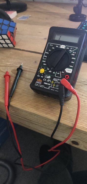
You have an accurate enough multimeter on a budget?
I was referring to one of these.
Your main difficulty is that you need to read above the max junction temperature of most semiconductors, which is in the region of 125 - 150 degrees C.
Otherwise it would be easy, the whole lot could be bought in a cheap chip upgrading my silicon diode.
A silicon dioded might survive to 210 but it would be such it and see. The forward voltage on the junction falls at 2millivolts per degress C.See also the discussion here
https://picaxeforum.co.uk/threads/temperature-sensor-up-to-250-degrees-c.26172/
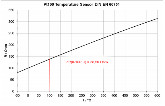
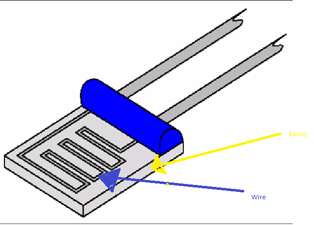
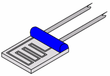
I have a multimeter which I seems like it could measure the resistance. The RTD i mentioned earlier from TE, has a data sheet which provides a graph. It shows the connection between the temperature and the resistance. My multimeter should quite easily be able to measure such high resistances. So I think I don't need the circuits you delivered me. I think it should be as easy as connecting the wires of my multimeter to the probes of the RTD without any other circuitry, read the readings of the multimeter (Ohms) and see what the according temperature would be. But would like I asked earlier it just be a matter of soldering the wires (PICTURE BLUE) to the ring and removing the epoxy glass (PICTURE YELLOW).
 0
0 -
4 minutes ago, studiot said:
The purpose of the large block is to make sure it is at a common temperature with Leidenfrost ring.
That also allows it to offer support for the thermometer.
You may need to scratch your head a bit to work out a suitable shape to fit to the ring.
Maybe a thick 'belt' .
All it is is a large block of metal to make sure you are measuring what you want to measure, not something else.Can you not follow the circuitry I linked to in Wikipedia for the RTD or thermistor ?
It is very easy, but may not be your subject, which is why I asked.
I did something very similar in my first year Chemistry, back in the 1960s with a tiny silicon diode temperature sensor.
But the temperature was lower.I will be eating right now. I will be back with an answer in about an hour or so.
42 minutes ago, studiot said:The purpose of the large block is to make sure it is at a common temperature with Leidenfrost ring.
That also allows it to offer support for the thermometer.
You may need to scratch your head a bit to work out a suitable shape to fit to the ring.
Maybe a thick 'belt' .
All it is is a large block of metal to make sure you are measuring what you want to measure, not something else.Can you not follow the circuitry I linked to in Wikipedia for the RTD or thermistor ?
It is very easy, but may not be your subject, which is why I asked.
I did something very similar in my first year Chemistry, back in the 1960s with a tiny silicon diode temperature sensor.
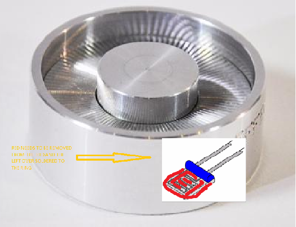
But the temperature was lower.Okay I took a look at the wikipedia page. I read about the different types of RTD's from which i concluded that a thin film RTD would probably work best. Like you said in the comment below "Can you not cement a small RTD (resistance temperature detector) to the ring and set up a suitable measuring bridge ?". You probably mean that I should remove the epoxy glass that is present on most thin film RTD's and solder the whole maze of wire tot the ring. Is the image below what you mean?
On 11/3/2019 at 3:26 PM, studiot said:Can you not cement a small RTD (resistance temperature detector) to the ring and set up a suitable measuring bridge ?
https://en.wikipedia.org/wiki/Resistance_thermometer
You have given no idea how big the ring is so I can't be more detailed.
You are also talking about a 'Measuring bridge' but can't you just measure the resistance using a multi meter?
0 -
13 minutes ago, studiot said:
How thick is the sidewall of the ring?
The probe on my thermometer is about 150 mm long and the bit in the photo is on the end so I don't think a horizontal hole in the sidewall will hold it or enable a proper measurement.
You might be able to dill down vertically enough though.I can't see you will have enough control with your hotplate heater to control the temperature well enough.
That is where a small sensor (the thermometer has quite a long thermal inertia) wouls be useful to control the power to the hotplate.What subject is this project in?
Do you have a project supervisor, I think you have enough to talk to him or her about it now ?
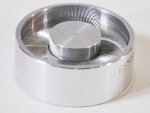
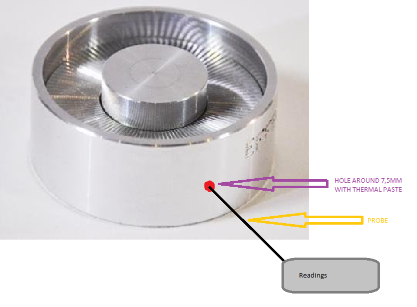
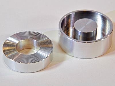
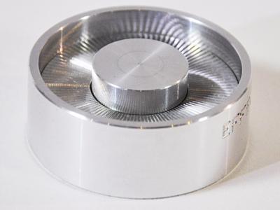
Well Like you can see on the third image the ring is split up in two parts. But I think I would quite easily be able to drill a hole all the way through the ring if needed (which means like 40mm deep). When the thermometer sticks out to the side whe could support it with something like a wooden block for example. I do have a supervisor, but he doesn't know much about the practical side of this stuff since he just studied physics, but even if he would know, he is not able to provide us with enough time to get this done.
Indeed a smaller sensor to me would seem better. But all those RTD, NTC etc. seem a little complicated to me. I can order a RTD, but what exactly am I supposed to do with em. Take this one for example: https://www.te.com/global-en/product-NB-PTCO-160.html or this ptc: https://www.reichelt.nl/ntc-weerstand-32-mw-10-kohm-epc-b57550g1103-p240079.html?&trstct=pol_7. Most of em offer a max temperature way over 210 degrees celsius so that won't be a problem. I know I can use the graph provided by the manufacturer to see what resistance belongs to what temperature that's not the problem. But I don't really understand how to place the RTD. The same way like the probe thermometer, or just put it on the surface also with thermal paste?We are working on some literature about how to conduct all this and if this way of generating energy could be used in our world or outer space. If you are interested we could show it.
Also like you can see in the video you provided. The guy is using a IR thermometer and a black block underneith the ring to measure the temperature. But I was told this doesn't give you an exact temperature reading. We really want to get the most accurate possible reading. Thanks again for helping. We really appreciate it!
0 -
Whoops my fault. It's supposed to be 40mm (4cm).
0 -
Okey this is exactly what I was looking for. I really see where you trying to get this. But just to make everything a lot more clear I have some pictures. You say a hole of 75mm deep. I think you mean 7.5mm deep because the ring is only 4cm wide and like 1.5cm high. The images don't include the object supporting the thermometer on the right side. I'm not 100% sure this will work as you can see in the 3rd image, the ring is split into two pieces. I can't use the top of the ring because there will be an aluminum thin circle plate on top of the whole ring (with the same 4cm diameter). I guess I can drill trough the two parts together and see if that would work. Hopefully this is clear.
 0
0 -
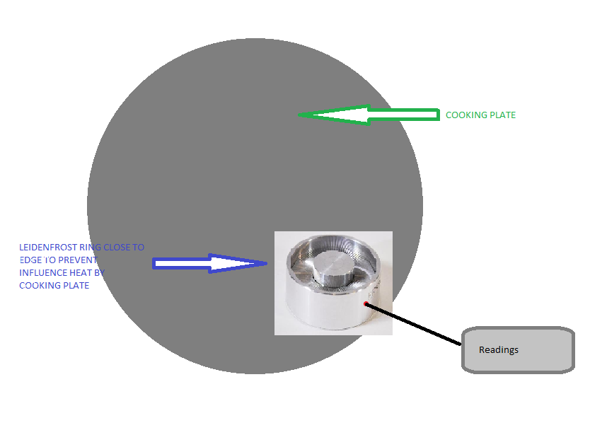
Okay I'l start from beginning to finish. I am with a friend of mine conducting an experiment with the Leidenfrost effect for our graduate year. Our goal is to create a system which is able to generate electrical energy using the Leidenfrost effect. Our setup looks like following: We have an electrical plate which heats up the ring, the plate is not capable of using a certain temperature. On the plate we put the Leidenfrost ring, with water in it of course, on top of that a little alluminium circle with holds 4 magnets which generates energy using the Lorentzforce. But when conducting this the Leidenfrost ring has to have a precise temperature to work correctly. This temperature is 210 degrees celsius. We thought we could just use a IR thermometer but these apparently don't work all to well with aluminium because of the emissivity. So now we are looking for a way to measure this temperature with an easy as possible way. Our budget is not crazy big and our knowledge about physics also isn't all too good. We know the basics and we are trying to accomplish our goals. Sorry for not being too clear about it and I hope this helps. My English is not all too good.
0 -
Would putting the thermistor circle on the surface give an accurate temperature? Seems like I would have to calibrate the sensors. But calibrating them would make me have to measure the temperature again.
0 -
Thanks for the fast reply. The ring is 400mm in diameter. How would we doing this exactly? This RTD is new for me so I don't exactly know what to do.
 0
0 -
So we are conducting a experiment with the Leidenfrost effect. We are trying to generate energy using this phenomenom. The leidenfrost effect occures whenever the temperature of the heated surface gets to around 210 degrees celsius. Reaching this exact temperature is important for the experiment. We thought about using a IR thermometer. But soon found out that because of the emissivity of Aluminium it wouldn't work. So we started to think about other ways to measure the temperature. We still haven't found a solution to this, but have come up to an idea. We thought painting the Aluminium Leidenfrost ring with some kind of black paint which an high conductance. What kind of paint or would anything else be better to determine the temperature of the ring. Any help is appreciated and sorry for any spelling mistakes made since I don''t speak English very well.
0

Measuring temperature of aluminium ring
in Classical Physics
Posted
But I want to bring back my initial idea. I thought of using black paint which I put on the sides of the ring. Because of the really high emissivity of a black surface it is ideal to measure the temperature of the paint using a IR thermometer which I already have. Only concern I have using this technique would be, that the paint's temperature might be a lot lower because of the bad heat conductivity of non metals. Although if I put a very thin layer on, I don't think it would really be a problem. Also I found this product: https://www.conrad.nl/p/voltcraft-tp-205-oppervlaktesensor-100-tot-300-c-sensortype-k-1661150. Might also we worth it.